finite element analysis of fracture in concrete structures state of the art
Bạn đang xem bản rút gọn của tài liệu. Xem và tải ngay bản đầy đủ của tài liệu tại đây (736.71 KB, 33 trang )
ACI 446.3R-97 became effective October 16, 1997.
Copyright
1998, American Concrete Institute.
All rights reserved including rights of reproduction and use in any form or by any
means, including the making of copies by any photo process, or by electronic or
mechanical device, printed, written, or oral, or recording for sound or visual reproduc-
tion or for use in any knowledge or retrieval system or device, unless permission in
writing is obtained from the copyright proprietors.
ACI Committee Reports, Guides, Standard Practices, and Commen-
taries are intended for guidance in planning, designing, executing,
and inspecting construction. This document is intended for the
use of individuals who are competent to evaluate the signifi-
cance and limitations of its content and recommendations and
who will accept responsibility for the application of the material
it contains. The American Concrete Institute disclaims any and all
responsibility for the stated principles. The Institute shall not be lia-
ble for any loss or damage arising therefrom.
Reference to this document shall not be made in contract docu-
ments. If items found in this document are desired by the Archi-
tect/Engineer to be a part of the contract documents, they shall be
restated in mandatory language for incorporation by the Architect/
Engineer.
446.3R-1
Fracture is an important mode of deformation and damage in both plain
and reinforced concrete structures. To accurately predict fracture behavior,
it is often necessary to use finite element analysis. This report describes the
state-of-the-art of finite element analysis of fracture in concrete. The two
dominant techniques used in finite element modeling of fracture—the dis-
crete and the smeared approaches—are described. Examples of finite ele-
ment analysis of cracking and fracture of plain and reinforced concrete
structures are summarized. While almost all concrete structures crack,
some structures are fracture sensitive, while others are not. Therefore, in
some instances it is necessary to use a consistent and accurate fracture
model in the finite element analysis of a structure. For the most general and
predictive finite element analyses, it is desirable to allow cracking to be
represented using both the discrete and the smeared approaches.
Keywords: Concrete; crack; cracking; damage; discrete cracking; finite
element analysis; fracture; fracture mechanics; reinforced concrete; struc-
tures; size effect; smeared cracking.
CONTENTS
Chapter 1—Introduction, p. 446.3R-2
1.1—Background
1.2—Scope of report
Chapter 2—Discrete crack models, p. 446.3R-3
2.1—Historical background
2.2—Linear Elastic Fracture Mechanics (LEFM)
2.3—Fictitious Crack Model (FCM)
2.4—Automatic remeshing algorithms
Chapter 3—Smeared crack models, p. 446.3R-13
3.1—Reasons for using smeared crack models
3.2—Localization limiters
Chapter 4-Literature review of FEM fracture
mechanics analyses, p. 446.3R-16
4.1—General
Finite Element Analysis of Fracture in Concrete Structures:
State-of-the-Art
Reported by ACI Committee 446
ACI 446.3R-97
Vellore Gopalaratnam
1
Chairman
Walter Gerstle
1,2
Secretary and Subcommittee Co-Chairman
David Darwin
1,2
Subcommittee Co-Chairman
Farhad Ansari Yeou-Sheng Jenq Philip C. Perdikaris
Zdenek P. Bazant
1,3
Mohammad T. Kazemi Gilles Pijaudier-Cabot
Oral Buyukozturk
1,3
Neven Krstulovic
Victor E. Saouma
1,3
Ignacio Carol
1
Victor C. Li Wimal Suaris
Rolf Eligehausen Jacky Mazars
Stuart E. Swartz
1,3
Shu-Jin Fang
1,3
Steven L. McCabe
1,3
Tianxi Tang
Ravindra Gettu Christian Meyer Tatsuya Tsubaki
Toshiaki Hasegawa
Hirozo Mihashi
1
Cumaraswamy Vipulanandan
Neil M. Hawkins Richard A. Miller Methi Wecharatana
Anthony R. Ingraffea
1,3
Sidney Mindess Yunping Xi
Jeremy Isenberg C. Dean Norman
Former member: Sheng-Taur Mao
1,3
1
Members of the Subcommittee that prepared this report
2
Principal authors
3
Contributing authors
446.3R-2 ACI COMMITTEE REPORT
4.2—Plain concrete
4.3—Reinforced concrete
4.4—Closure
Chapter 5—Conclusions, p. 446.3R-26
5.1—General summary
5.2—Future work
Chapter 6—References, p. 446.3R-27
Appendix-Glossary, p. 446.3R-32
CHAPTER 1—INTRODUCTION
In this report, the state-of-the-art in finite element modeling
of concrete is viewed from a fracture mechanics perspective.
Although finite element methods for modeling fracture are un-
dergoing considerable change, the reader is presented with a
snapshot of current thinking and selected literature on the topic.
1.1—Background
As early as the turn of the 19th century, engineers realized
that certain aspects of concrete behavior could not be described
or predicted based upon classical strength of materials tech-
niques. As the discipline of fracture mechanics has developed
over the course of this century (and indeed, is still developing),
it has become clear that a correct analysis of many concrete
structures must include the ideas of fracture mechanics.
The need to apply fracture mechanics results from the fact
that classical mechanics of materials techniques are inade-
quate to handle cases in which severe discontinuities, such as
cracks, exist in a material. For example, in a tension field, the
stress at the tip of a crack tends to infinity if the material is
assumed to be elastic. Since no material can sustain infinite
stress, a region of inelastic behavior must therefore surround
the crack tip. Classical techniques cannot, however, handle
such complex phenomena. The discipline of fracture me-
chanics was developed to provide techniques for predicting
crack propagation behavior.
Westergaard (1934) appears to have been the first to apply
the concepts of fracture mechanics to concrete beams. With
the advent of computers in the 1940s, and the subsequent
rapid development of the finite element method (FEM) in the
1950s, it did not take long before engineers attempted to an-
alyze concrete structures using the FEM (Clough 1962, Ngo
and Scordelis 1967, Nilson 1968, Rashid 1968, Cervenka
and Gerstle 1971, Cervenka and Gerstle 1972). However,
even with the power of the FEM, engineers faced certain
problems in trying to model concrete structures. It became
apparent that concrete structures usually do not behave in a
way consistent with the assumptions of classical continuum
mechanics (Bazant 1976).
Fortunately, the FEM is sufficiently general that it can
model continuum mechanical phenomena as well as discrete
phenomena (such as cracks and interfaces). Engineers per-
forming finite element analysis of reinforced concrete struc-
tures over the past thirty years have gradually begun to
recognize the importance of discrete mechanical behavior of
concrete. Fracture mechanics may be defined as that set of
ideas or concepts that describe the transition from continu-
ous to discrete behavior as separation of a material occurs.
The two main approaches used in FEM analysis to represent
cracking in concrete structures have been to 1) model cracks
discretely (discrete crack approach); and 2) model cracks in
a smeared fashion by applying an equivalent theory of con-
tinuum mechanics (smeared crack approach). A third ap-
proach involves modeling the heterogeneous constituents of
concrete at the size scale of the aggregate (discrete particle
approach) (Bazant et al. 1990).
Kaplan (1961) seems to have been the first to have per-
formed physical experiments regarding the fracture mechan-
ics of concrete structures. He applied the Griffith (1920)
fracture theory (modified in the middle of this century to be-
come the theory of linear elastic fracture mechanics, or
LEFM) to evaluate experiments on concrete beams with
crack-simulating notches. Kaplan concluded, with some res-
ervations, that the Griffith concept (of a critical potential en-
ergy release rate or critical stress intensity factor being a
condition for crack propagation) is applicable to concrete.
His reservations seem to have been justified, since more re-
cently it has been demonstrated that LEFM is not applicable
to typical concrete structures. In 1976, Hillerborg, Modeer
and Petersson studied the fracture process zone (FPZ) in
front of a crack in a concrete structure, and found that it is
long and narrow. This led to the development of the fictitious
crack model (FCM) (Hillerborg et al. 1976), which is one of
the simplest nonlinear discrete fracture mechanics models
applicable to concrete structures.
Finite element analysis was first applied to the cracking of
concrete structures by Clough (1962) and Scordelis and his
coworkers Nilson and Ngo (Nilson 1967, Ngo and Scordelis
1967, Nilson 1968). Ngo and Scordelis (1967) modeled dis-
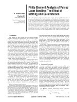
crete cracks, as shown in Fig. 1.1, but did not address the
problem of crack propagation. Nilson (1967) modeled pro-
gressive discrete cracking, not by using fracture mechanics
techniques, but rather by using a strength-based criterion.
The stress singularity that occurs at the crack tip was not
modeled. Thus, since the maximum calculated stress near the
tip of a crack depends upon element size, the results were
mesh-dependent (nonobjective). Since then, much of the re-
search and development in discrete numerical modeling of
fracture of concrete structures has been carried out by In-
graffea and his coworkers (Ingraffea 1977, Ingraffea and
Manu 1980, Saouma 1981, Gerstle 1982, Ingraffea 1983,
Gerstle 1986, Wawrzynek and Ingraffea 1987, Swenson and
Ingraffea 1988, Wawrzynek and Ingraffea 1989, Ingraffea
1990, Martha et al. 1991) and by Hillerborg and coworkers
(Hillerborg et al. 1976, Petersson 1981, Gustafsson 1985).
Another important approach to modeling of fracture in
concrete structures is called the smeared crack model (Rash-
id 1968). In the smeared crack model, cracks are modeled by
changing the constitutive (stress-strain) relations of the solid
continuum in the vicinity of the crack. This approach has
been used by many investigators (Cervenka and Gerstle
1972, Darwin and Pecknold 1976, Bazant 1976, Meyer and
Bathe 1982, Chen 1982, Balakrishnan and Murray 1988).
Bazant (1976) seems to have been the first to realize that, be-
cause of its strain-softening nature, concrete cannot be mod-
eled as a pure continuum. Zones of damage tend to localize
to a size scale that is of the order of the size of the aggregate.
446.3R-3FINITE ELEMENT ANALYSIS OF FRACTURE IN CONCRETE STRUCTURES
Therefore, for concrete to be modeled as a continuum, ac-
count must be taken of the size of the heterogeneous struc-
ture of the material. This implies that the maximum size of
finite elements used to model strain softening behavior
should be linked to the aggregate size. If the scale of the
structure is small, this presents no particular problem. How-
ever, if the scale of the structure is large compared to the size
of its internal structure (aggregate size), stress intensity fac-
tors (fundamental parameters in LEFM) may provide a more
efficient method for modeling crack propagation than the
smeared crack approach (Griffith 1920, Bazant 1976). Most
structures of interest are of a size between these two ex-
tremes, and controversy currently exists as to which of these
approaches (discrete fracture mechanics or smeared cracking
continuum mechanics) is more effective. This report de-
scribes both the discrete and smeared cracking methods.
These two approaches, however, are not mutually exclusive,
as shown, for example, by Elices and Planas (1989).
When first used to model concrete structures, it was expect-
ed that the FEM could be used to solve many problems for
which classical solutions were not available. However, even
this powerful numerical tool has proven to be difficult to apply
when the strength of a structure or structural element is con-
trolled by cracking. When some of the early finite element
analyses are studied critically in light of recent developments,
they are found to be nonobjective or incorrect in terms of the
current understanding of fracture mechanics, although many
produced a close match with experimental results. It is now
clear that any lack of success in these models was not due to a
weakness in the FEM, but rather due to incorrect approaches
used to model cracks. In many cases, success can be achieved
only if the principles of fracture mechanics are brought to bear
on the problem of cracking in plain and reinforced concrete.
These techniques have not only proven to be powerful, but
have begun to provide explanations for material behavior and
predictions of structural response that have previously been
poorly or incorrectly understood.
While some preliminary research has been performed in the
finite element modeling of cracking in three-dimensional struc-
tures (Gerstle et al. 1987, Wawrzynek and Ingraffea 1987, In-
graffea 1990, Martha et al. 1991), the state-of-the-art in the
fracture analysis of concrete structures seems currently to be
generally limited to two-dimensional models of structures.
1.2—Scope of report
Several previous state-of-the-art reports and symposium
proceedings discuss finite element modeling of concrete
structures (ASCE Task Committee 1982, Elfgren 1989,
Computer-Aided 1984, 1990, Fracture Mechanics 1989, Fir-
rao 1990, van Mier et al. 1991, Concrete Design 1992, Frac-
ture 1992, Finite Element 1993, Computational Modeling
1994, Fracture and Damage 1994, Fracture 1995). This re-
port provides an overview of the topic, with emphasis on the
application of fracture mechanics techniques. The two most
commonly applied approaches to the FEM analysis of frac-
ture in concrete structures are emphasized. The first ap-
proach, described in Chapter 2, is the discrete crack model.
The second approach, described in Chapter 3, is the smeared
crack model. Chapter 4 presents a review of the literature of
applications of the finite element technique to problems in-
volving cracking of concrete. Finally, some general conclu-
sions and recommendations for future research are given in
Chapter 5.
No attempt is made to summarize all of the literature in the
area of FEM modeling of fracture in concrete. There are sev-
eral thousand references dealing simultaneously with the
FEM, fracture, and concrete. An effort is made to crystallize
the confusing array of approaches. The most important ap-
proaches are described in detail sufficient to enable the reader
to develop an overview of the field. References to the litera-
ture are provided so that the reader can obtain further details,
as desired. The reader is referred to ACI 446.1R for an intro-
duction to the basic concepts of fracture mechanics, with spe-
cial emphasis on the application of the field to concrete.
CHAPTER 2—DISCRETE CRACK MODELS
A discrete crack model treats a crack as a geometrical entity.
In the FEM, unless the crack path is known in advance, dis-
crete cracks are usually modeled by altering the mesh to ac-
commodate propagating cracks. In the past, this remeshing
process has been a tedious and difficult job, relegated to the
analyst. However, newer software techniques now enable the
remeshing process, at least in two-dimensional problems, to
be accomplished automatically by the computer. A zone of in-
elastic material behavior, called the fracture process zone
(FPZ), exists at the tip of a discrete crack, in which the two
sides of the crack may apply tractions to each other. These
Fig. 1.1—The first finite element model of a cracked reinforced concrete beam (Ngo and
Scordelis 1967)
446.3R-4 ACI COMMITTEE REPORT
tractions are generally thought of as nonlinear functions of the
relative displacements between the sides of the crack.
2.1—Historical background
Finite element modeling of discrete cracks in concrete
beams was first attempted by Ngo and Scordelis (1967) by
introducing cracks into the finite element mesh by separating
elements along the crack trajectory, as shown in Fig. 1.1.
They did not, however, attempt to model crack propagation.
Had they done so, they would have found many problems,
starting with the fact that the stresses at the tips of the cracks
increase without bound as the element size is reduced, and no
convergence (of crack tip stresses) to a solution would have
been obtained. Also, in light of the findings of Hillerborg et
al. (1976) that a crack in concrete has a gradually softening
region of significant length at its tip, it was inaccurate to
model cracks with traction-free surfaces. It is notable that
Ngo and Scordelis also grappled with the theoretically diffi-
cult issue of connecting the reinforcing elements with the
concrete elements via “bond-link” elements.
Nilson (1967, 1968) was the first to consider a FEM model
to represent propagation of discrete cracks in concrete struc-
tures. Quoting from his thesis (Nilson 1967):
The present analysis includes consideration of progressive
cracking. The uncracked member is loaded incrementally until
previously defined cracking criteria are exceeded at one or
more locations in the member. Execution terminates, and the
computer output is subjected to visual inspection. If the average
value of the principal tensile stress in two adjacent elements
exceeds the ultimate tensile strength of the concrete, then a
crack is defined between those two elements along their com-
mon edge. This is done by establishing two disconnected nodal
points at their common corner or corners where there formerly
was only one. When the principal tension acts at an angle to the
boundaries of the element, then the crack is defined along the
side most nearly normal to the principal tension direction.
The newly defined member, with cracks (and perhaps partial
bond failure), is then re-loaded from zero in a second loading
stage, also incrementally applied to account for the nonlinear-
ities involved. Once again the execution is terminated if
cracking criteria are exceeded. The incremental extension of
the crack is recorded, and the member loaded incrementally
in the third stage, and so on. In this way, crack propagation
may be studied and the extent of cracking at any stage of
loading is obtained.
The problems associated with this approach to discrete
crack propagation analysis are three-fold: (1) cracks in con-
crete structures of typical size scale develop gradually (Hill-
erborg et al. 1976), rather than abruptly; (2) the procedure
forces the cracks to coincide with the predefined element
boundaries; and (3) the energy dissipated upon crack propa-
gation is unlikely to match that in the actual structure, result-
ing in a spurious solution.
In the 1970s, great strides were made in modeling of
LEFM using the FEM. Chan, Tuba, and Wilson (1970)
pointed out that a large number of triangular constant stress
finite elements are required to obtain accurate stress intensity
factor solutions using a displacement correlation technique
(about 2000 degrees of freedom are required to obtain 5 per-
cent accuracy in the stress intensity factor solution). At this
time, singular finite elements had not yet been developed
(singular elements exactly model the stress state at the tip of
a crack). In their paper, Chan et al. pointed out that there
were then three ways to obtain stress intensity factors from a
finite element solution: (1) displacement correlation; (2)
stress correlation; and (3) energy release rate methods (line
integral or potential energy derivative approaches).
Wilson (1969) appears to have been the first to have devel-
oped a singular crack tip element. Shortly thereafter, Tracey
(1971) developed a triangular singular crack tip finite ele-
ment that required far fewer degrees of freedom than analy-
sis with regular elements to obtain accurate stress intensity
factor. At about the same time, Tong, Pian, and Lasry (1973)
developed and experimented with hybrid singular crack tip
elements (including stress-intensity factors, as well as dis-
placement components, as degrees of freedom).
Jordan (1970) noticed that shifting the midside nodes
along adjacent sides of an eight-noded quadrilateral toward
the corner node by one-quarter of the element’s side length
caused the Jacobian of transformation to become zero at the
corner node of the element. This led to the discovery by Hen-
shell and Shaw (1975) and Barsoum (1976) that the shift al-
lowed the singular stress field to be modeled exactly for an
elastic material. Thus, standard quadratic element with mid-
side nodes shifted to the quarter-points can be used as a r
-1/2
singularity element for modeling stresses at the tip of a crack
in a linear elastic medium.
The virtual crack extension method for calculating Mode I
stress intensity factors was developed independently by
Hellen (1975) and Parks (1974). In this method, G, the rate
of change of potential energy per unit crack extension, is cal-
culated by a finite difference approach. This approach does
not require the use of singular elements to obtain Mode I
(opening mode) stress-intensity factors. Recently, it has been
found that by decomposing the displacement field into sym-
metric and antisymmetric components with respect to the
crack tip, the method may also be extended to calculate
Mode II (sliding) and Mode III (tearing) energy release rates
and stress-intensity factors (Sha and Yang 1990, Shumin and
Xing 1990, Rahulkumar 1992).
Having developed the capability to compute stress intensity
factors using the FEM, the next big step was to model linear
elastic crack propagation using fracture mechanics principles.
This was started for concrete by Ingraffea (1977), and continued
by Ingraffea and Manu (1980), Saouma (1981), Gerstle (1982,
1986), Wawrzynek and Ingraffea (1986), and Swenson and In-
graffea (1988). These attempts were primarily aimed at facilitat-
ing the process of discrete crack propagation through automatic
crack trajectory computations and semi-automatic remeshing to
allow discrete crack propagation to be modeled. Currently, the
main technical difficulties involved in modeling of discrete
LEFM crack propagation are in the 3D regime. In 2D applica-
tions, automatic propagation and remeshing algorithms have
been reasonably successful and are improving. In three-dimen-
sional modeling, automatic remeshing algorithms are on the
verge of being sufficiently developed to model general crack
propagation, and computers are just becoming powerful enough
446.3R-5FINITE ELEMENT ANALYSIS OF FRACTURE IN CONCRETE STRUCTURES
to accurately solve problems with complex geometries caused
by the propagation of a number of discrete cracks.
Another development in discrete crack modeling of con-
crete structures has been the realization that LEFM does not
apply to structural members of normal size, because the FPZ
in concrete is relatively large compared to size of the mem-
ber. This has led to the development of finite element mod-
eling of nonlinear discrete fracture—usually as the
implementation of the fictitious crack model (FCM) (Hiller-
borg et al. 1976), in which the crack is considered to be a
strain softening zone modeled by cohesive nodal forces or by
interface elements [first developed by Goodman, Taylor, and
Brekke (1968)].
Finally, there appear to be situations in which even the
FCM seems inadequate to model realistic concrete behavior
in the FPZ. In this case, a smeared crack model of some kind,
as described in Chapter 3, becomes necessary.
2.2—Linear Elastic Fracture Mechanics (LEFM)
Linear elastic fracture mechanics (LEFM) is an important
approach to the fracture modeling of concrete structures,
even though it is only applicable to very large (say several
meters in length) cracks. For cracks that are smaller than this,
LEFM over-predicts the load at which the crack will propa-
gate. To determine whether LEFM may be used or whether
nonlinear fracture mechanics is necessary for a particular
problem, one must determine the size of the steady state frac-
ture process zone (FPZ) compared to the least dimension as-
sociated with the crack tip (ACI 446.1R). The FPZ size and
the crack tip least dimension are discussed next.
The FPZ may be defined as the area surrounding a crack tip
within which inelastic material behavior occurs. The FPZ size
grows as load is applied to a crack, until it has developed to the
point that the (traction-free) crack begins to propagate. If the
size of the FPZ is small compared to other dimensions in the
structure, then the assumptions of LEFM lead to the conclu-
sion that the FPZ will exhibit nonchanging characteristics as
the crack propagates. This is called the steady state FPZ. The
size of the steady state FPZ depends only upon the material
properties. In concrete, as opposed to metals, the FPZ can of-
ten be thought of as an interface separation phenomenon, with
little accompanying volumetric damage. The characteristics of
the steady state FPZ depend upon the aggregate size, shape
and strength, and upon microstructural details of the particular
concrete under consideration. The FPZ was first studied in de-
tail by Hillerborg, Modeer, and Petersson (1976). The size of
the FPZ depends on the model used in the study. For example,
in the analysis carried out by Ingraffea and Gerstle (1985) for
normal strength concrete, the steady state FPZ ranged from 6
in. (150 mm) to 3 ft (1 m) in length.
The least dimension (L.D.) associated with a crack tip is
best defined with the aid of Fig. 2.1 (Gerstle and Abdalla
1990). The least dimension is used to calculate an approximate
radius surrounding the crack tip within which the singular
stress field can be guaranteed to dominate the solution. The
least dimension can be defined as the distance from the crack
tip to the nearest discontinuity that might cause a local distur-
bance in the stress field. Fig. 2.1(a) shows the case where the
crack tip L.D. is controlled by the proximity to the crack tip of
a free surface. Fig. 2.1(b) shows the case where the least di-
mension is the crack length itself. Fig. 2.1(c) shows the case
where the least dimension is controlled by the crack tip pass-
ing close by a reinforcing bar. [Of course, if the reinforcement
is considered as a smeared (rather than discrete) constituent of
the reinforced concrete composite, then it need not be modeled
discretely, and the constitutive relations and the FPZ must cor-
respondingly include the effect of the smeared reinforcing
bars.] Fig. 2.1(d) shows the case where the least dimension is
controlled by the size of the ligament (the remaining un-
cracked dimension of the member). In Fig. 2.1(e), the least di-
mension is governed by a kink in the crack. Finally, Fig. 2.1(f)
shows an example of the least dimension being controlled by
the radius of curvature of the crack.
As explained in Chapter 2 of ACI 446.1R, one of the funda-
mental assumptions of LEFM is that the size of the FPZ is neg-
ligible (say, no more than one percent of the least dimension
associated with the crack tip). It is this assumption that allows
for a theoretical stress distribution near the crack tip in linear
elastic materials, in which the stress varies with r
-1/2
, in which
r is the distance from the crack tip. Stress-intensity factors K
I
,
K
II
, and K
III
are defined as the magnitudes of the singular
stress fields for Mode I, Mode II, and Mode III cracks, respec-
tively. If the FPZ is not small compared to the least dimension,
then singular stress fields may not be assumed to exist, and
consequently, K
I
, K
II
, and K
III
are not defined for such a crack
tip. In such a case, the FPZ must be modeled explicitly and a
nonlinear fracture model is required.
As mentioned earlier, fracture process zones in concrete
can be on the order of 1 ft (0.3 m) or more in length. For the
great majority of concrete structures, least dimensions are
less than several feet. Therefore, fracture in these types of
structures must be modeled using nonlinear fracture me-
chanics. Only in very large concrete structures, for example,
dams, is it possible to apply LEFM appropriately. For dams
with large aggregate, possibly on the size scale of meters,
LEFM may not be applicable because of the correspondingly
larger size of the FPZ.
Even though it is recognized that LEFM is not applicable
to typical concrete structures, it is appropriate to review the
details of the finite element analysis of LEFM. Then, in Sec-
tion 2.3, the finite element analysis of nonlinear discrete
fracture mechanics will be presented.
2.2.1 Fracture criteria: K, G, mixed-mode models
Stress-intensity factors K
I
, K
II
, and K
III
or energy release
rates G
I
, G
II
, and G
III
may be used in LEFM to predict crack
equilibrium conditions and propagation trajectories. There
are several theories that can be used to predict the direction
of crack propagation. These include, for quasistatic prob-
lems, the maximum circumferential tensile stress theory (Er-
dogan and Sih 1963), the maximum energy release rate
theory (Hussain et al. 1974), and the minimum strain energy
density theory (Sih 1974). These theories all give practically
the same crack trajectories and loads at which crack exten-
sion takes place, and therefore the theory of choice depends
primarily upon convenience of implementation. Each of
these theories may also be applied to dynamic fracture prop-
agation problems (Swenson 1986). As in metals, cyclic fa-
tigue crack propagation in concrete may be modeled with the
446.3R-6 ACI COMMITTEE REPORT
Paris Model (Barsom and Rolfe 1987) in conjunction with
the mixed-mode crack propagation theories just mentioned.
However, it is rare that an unreinforced concrete structure is
both (1) large enough to merit LEFM treatment and (2) sub-
ject to fatigue loading.
In most of the literature on discrete crack propagation in
concrete structures, it has been considered necessary to mod-
el the stress singularity at a crack tip using singular elements.
However, accurate results can also be obtained without mod-
eling the stress singularity, but rather by calculating the en-
ergy release rates directly (Sha and Yang 1990, Rahulkumar
1992). However, for a comprehensive treatment, we discuss
modeling of stress singularities next.
2.2.2 FEM modeling of singularities and stress intensity
factors
Special-purpose singular finite elements have been creat-
ed with stress-intensity factors included explicitly as de-
grees-of-freedom (Byskov 1970, Tong and Pian 1973, Atluri
et al. 1975, Mau and Yang 1977). However, these are spe-
cial-purpose hybrid elements that are not usually included in
standard displacement-based finite element codes, and will
not be discussed in further detail here. The most successful
displacement-based elements are the Tracey element
(Tracey 1971) and the quarterpoint quadratic triangular iso-
parametric element (Henshell and Shaw 1975, Barsoum
1976, Saouma 1981, Saouma and Schwemmer 1984). Most
general purpose finite element codes unfortunately do not in-
clude the Tracey element, but they do include six noded tri-
angular elements, which can then be used as singular
quarterpoint crack tip elements.
After a finite element analysis has been completed, stress-
intensity factors can be extracted by several approaches. The
most accurate methods are the energy approaches: the J-in-
tegral, virtual crack extension, or stiffness derivative meth-
ods. However, these approaches are not as easy to apply for
the case of mixed-mode crack propagation, and have been
applied only rarely to three-dimensional problems (Shivaku-
mar et al. 1988). Simpler to apply (for mixed-mode fracture
Fig. 2.1—Examples illustrating the concept of “least dimension (L.D.)” associated with a
crack tip (Gerstle and Abdalla 1990)
446.3R-7FINITE ELEMENT ANALYSIS OF FRACTURE IN CONCRETE STRUCTURES
mechanics) are the displacement correlation techniques. Be-
cause these techniques sample local displacements at various
points, and correlate these with the theoretical displacement
field associated with a crack tip, they are generally not as ac-
curate as the energy approaches, which use integrated infor-
mation. The displacement correlation techniques are usually
used only when singular elements are employed, while the
energy approaches are used for determining energy release
rates for cracks that may or may not be discretized with the
help of singular elements.
The displacement and stress correlation techniques assume
that the finite element solution near the crack tip is of the same
form as the singular near-field solution predicted by LEFM
(Broek 1986). By matching the (known) finite element solu-
tion with the (known, except for K
I
, K
II
, and K
III
) theoretical
near-field LEFM solution, it is possible to calculate the stress-
intensity factors. Since only three equations are needed to ob-
tain the three stress-intensity factors, while many points that
can be matched, there are many possible schemes for correla-
tion. These include matching nodal responses only on the
crack surfaces and least-squares fitting of all of the nodal re-
sponses associated with the singular elements.
The displacement correlation approach is more accurate
than the stress correlation approach because displacements
converge more rapidly than stresses using the FEM. There-
fore only the displacement correlation approach is discussed
in detail here (Shih et al. 1976).
Consider a linear elastic isotropic material with Young’s
modulus E and Poisson’s ratio
ν. For the case of plane strain,
the near-field displacements (u,v), in terms of polar coordi-
nates r and
θ, shown in Fig. 2.2, are given by:
(2.1)
(2.2)
in which u and v are parallel and perpendicular to the crack
face, respectively.
Now consider a crack tip node surrounded by quarter point
triangular elements shown in Fig. 2.2. Interpolating the radial
coordinate, r, along the side AC, by using quadratic shape func-
tions associated with nodes A, B, and C, and solving for the nat-
ural triangular area coordinate
ξ
1
in terms of r, we obtain:
(2.3)
where L is the length of the side AC. Now interpolating the
displacements along the side AC by using the computed dis-
placement components at nodes A, B, and C, and using Eq.
u
2K
I
1
ν
+
()
E
r
2π
θ
2
12ν–
2
θ
2
sin++cos=
2K
II
1 ν+()
E
r
2π
θ
2
22ν–
2 θ
2
cos+sin
v
2 K
I
1 ν+()
E
r
2π
θ
2
22ν–
2 θ
2
cos–+sin=
2K
II
1 ν+()
E
r
2π
θ
2
1–2ν
2 θ
2
sin++cos
ξ
1
1
r
L
–=
Fig. 2.2—Nomenclature for 2D quarter point singular isoparametric elements
446.3R-8 ACI COMMITTEE REPORT
(2.3), we obtain the displacements along the crack surface
AC in terms of r. These are given by:
(2.4)
(2.5)
Similarly the displacements alongside AE can be written as:
(2.6)
(2.7)
Subtracting Eq. 2.6 from 2.4 and subtracting 2.7 from 2.5,
the crack opening displacement (COD) and crack sliding dis-
placement (CSD) are computed as:
(2.8)
(2.9)
Analytical solutions for COD and CSD can be obtained by
evaluating the displacement components u and v given by
Eqs. 2.1 and 2.2 for
θ = +π and θ = -π and subtracting the val-
ues at
θ = -π from the values at θ = +π. Equating the like
terms in the finite element and the analytical COD and CSD
profiles, the stress intensity factors are given by:
(2.10)
(2.11)
Thus by meshing the crack tip region with quarter-point
quadratic triangular elements and solving for the displace-
ments, the stress intensity factors can be computed by using
Eqs. 2.10 and 2.11. This technique does not require any spe-
cial subroutines to develop the stiffness matrix for the singu-
lar elements. A single subroutine can be written to calculate
the length L of the sides AC and AE, retrieve the displace-
ment components at the nodes A, B, C, D, and E and thereby
compute the stress-intensity factors using Eqs. 2.10 and 2.11.
Ingraffea and Manu (1980) have developed similar equa-
tions for the computation of stress-intensity factors in three
dimensions with quarterpoint quadratic elements. In three di-
mensions, the crack tip is replaced by the crack front, the
crack edge by the crack face.
Energy approaches for extracting stress-intensity factors
make use of the fact that K
I
= [EG
I
]
1/2
, K
II
= [EG
II
]
1/2
, K
III
= [EG
III
/(1 + ν)]
1/2
for plane stress and K
I
= [EG
I
/1 - ν
2
)]
1/2
,
K
II
= [EG
II
/(1 - ν
2
)]
1/2
, K
III
= [EG
III
/(1 + ν)]
1/2
for plane
strain. Here, G
I
, G
II
, and G
III
are the potential energy release
rates created by collinear crack extension due to Mode I,
Mode II, and Mode III deformations, respectively. In the
simplest approach, the total energy release rate, G = G
I
+ G
II
+ G
III
can be calculated by performing an analysis, calculat-
ing the total potential energy,
π
A
, collinearly extending the
crack by a small amount
∂a, reperforming the analysis to ob-
tain
π
B
, and then using a finite difference to approximate G
as G = (
π
A
- π
B
)/ ∂a. If G
I
, G
II
, and G
III
are required separate-
ly, they can be calculated by decomposing the crack tip dis-
placement and the stress fields into Mode I, Mode II, and
Mode III components (Rahulkumar 1992).
The stiffness derivative method for determination of the
stress-intensity factor for Mode I (2D and 3D) crack prob-
lems was introduced by Parks (1974). The method is equiv-
alent to the J-integral approach (described later).
With reference to Fig. 2.3, any set of finite elements that
forms a closed path around the crack tip may be chosen. The
simplest set to choose is the set of elements around the crack tip.
The stiffness derivative method involves determination of
the stress-intensity factor from a calculation of the potential
energy decrease per unit crack advance, G. For plane strain
and unit thickness, the relation between K
I
and G is
(2.12)
in which P is the potential energy, a is the crack length, E is
Young’s modulus, and
ν is Poisson’s ratio.
Parks (1974) shows that the potential energy,
π, in the
problem is given by:
(2.13)
in which [K] is the global stiffness matrix, and {f} is the vec-
tor of prescribed nodal loads. Eq. 2.13 is differentiated with
respect to crack length, a, to obtain the energy release rate as
(2.14)
The matrix represents the change in the structure stiff-
ness matrix per unit of crack length advance. The term is
nil if the crack tip area is unloaded. The key to understanding
the stiffness derivative method is to imagine representing an
increment of crack advance with the mesh shown in Fig. 2.3
by rigidly translating all nodes on and within a contour
Γ
o
(see
Fig. 2.3) about the crack tip by an infinitesimal amount
∆a in
the x-direction. All nodes on and outside of contour
Γ
1
remain
in their initial position. Thus the global stiffness matrix [K],
which depends on only individual element geometries, dis-
placement functions, and elastic material properties, remains
unchanged in the regions interior to
Γ
o
and exterior to Γ
1
, and
the only contributions to the first term of Eq. 2.14 come from
the band of elements between the contours
Γ
o
and Γ
1
. The
structure stiffness matrix [K] is the sum over all elements of
the element stiffness matrices [K
i
]. Therefore,
uu
A
3u
A
–4u
B
u
C
–+()
r
L
2u
A
4u
B
–2u
C
+
()
r
L
++=
vv
A
3v
A
–4v
B
v
C
–+()
r
L
2v
A
4v
B
–2v
C
+
()
r
L
++=
uu
A
3u
A
–4u
D
u
E
–+()
r
L
2u
A
4u
D
–2u
E
+
()
r
L
++=
vv
A
3 v
A
–4v
D
v
E
–+()
r
L
2v
A
4v
D
–2v
E
+
()
r
L
++=
COD4v
B
v
C
–4v
D
– v
E
+()
r
L
4v
B
2 v
C
+()–4v
D
2 v
E
–+
()
r
L
+=
CSD4u
B
u
C
–4u
D
– u
E
+()
r
L
4u
B
–2u
C
4 u
D
2u
E
–++
()
r
L
+=
K
I
2π
L
E
21ν
+
()34ν
–
()
4v
B
v
D
–()v
E
v
C
–+
[]
=
K
II
2π
L
E
21ν
+
()34ν
–
()
4u
B
u
D
–()u
E
u
C
–+
[]
=
G
∂π
∂a
load
–
1 ν
2
–
()
E
K
I
2
==
π
1
2
u{}
T
K[]u{} u{}
T
f
{}
–=
∂π–
∂a
load
1
2
u{}
T ∂ K[]
∂a
u{}– u{}
T ∂ f{}
∂a
– K
1
2
1 ν
2
–
()
E
==
∂
K
[]
∂a
∂
f
{}
∂a
446.3R-9FINITE ELEMENT ANALYSIS OF FRACTURE IN CONCRETE STRUCTURES
Fig. 2.4—J-Integral nomenclature (Rice 1968)
Fig. 2.3—Stiffness derivature approach for advancing nodes (Parks 1978)
446.3R-10 ACI COMMITTEE REPORT
(2.15)
in which is the element stiffness matrix of an element be-
tween the contours
Γ
o
and Γ
1
, and N
c
is the number of such el-
ements. The derivatives of the element stiffness matrices can
be calculated numerically by taking a finite difference:
(2.16)
The method may be extended to mixed-mode cracks.
The J-Integral method (Rice 1968) for determining the en-
ergy release rate of a Mode I crack is useful for determining
energy release rates, not only for LEFM crack propagation,
but also for nonlinear fracture problems. For a two-dimen-
sional problem, a path
Γ is traversed in a counter-clockwise
sense between the two crack surfaces, as shown in Fig. 2.4.
The J-integral is defined as:
(2.17)
where summation over the range of repeated indices is un-
derstood.
Here, , i,j = 1, 2, 3 is the strain energy density,
s is the arc length, and p
i
is the traction exerted on the body
bounded by
Γ and the crack surface. The J-integral is equal
to the energy release rate G of the crack (Rice 1968).
The J-integral method can be relatively easily applied to a
crack problem whose stress and displacement solution is
known, and is not limited to linear materials. However, elas-
ticity or pseudoelasticity along the contour,
Γ, is a require-
ment (Rice 1968).
Alternate energy approaches for extraction of stress-inten-
sity factors from three-dimensional problems have been de-
veloped (Shivakumar et al. 1988). Bittencourt et al. (1992)
provide a single reference that compares the displacement
correlation, the J-integral, and the modified crack closure in-
tegral techniques for obtaining stress-intensity factors.
When using triangular quarter-point elements to model the
singularity at a crack tip, meshing guidelines have been sug-
gested by a number of researchers (Ingraffea 1983, Saouma
and Schwemmer 1984, Gerstle and Abdalla 1990). When us-
ing the displacement correlation technique to extract stress-
intensity factors, the guidelines are summarized as follows:
1. Use a 2 x 2 (reduced) integration scheme (Saouma and
Schwemmer 1984).
2. To achieve 5 percent maximum expected error in any
stress component due to any mixed-mode problem, use at
least eight approximately equiangular singular elements ad-
jacent to the crack tip node. For 1 percent error, 16 singular
elements should be used (Gerstle and Abdalla 1990).
3. There is an optimal size for the crack tip elements. If
they are too small, they do not encompass the near-field re-
gion of the solution, and surrounding regular elements will
be “wasted” modeling the near field. If they are too big, they
do not model the far-field solution accurately. The singular
elements should be related to the size of the region within
which near-field solution is valid. For 5 percent accuracy in
stress-intensity factors, the singular elements should be
about
1
/
5
of the size of the least dimension associated with
the crack tip. For one percent accuracy, the singular elements
should be about
1
/
20
of the size of the least dimension asso-
ciated with the crack tip (Gerstle and Abdalla 1990).
4. Regular quadratic elements should be limited in size, s,
by their clear distance, b, from a crack tip. The ratio of s/b
should not exceed unity to achieve 30 percent error, and
should not exceed 0.2 to achieve 1 percent error in the near
field solution (Gerstle and Abdalla 1990).
The meshing criteria given above show that a large num-
ber of elements are required at a crack tip to obtain accurate
near-field stresses. Experience shows that 300 degrees of
freedom are required per crack tip to reliably obtain 5 per-
cent accuracy in the near field stresses (Gerstle and Abdalla
1990). This becomes prohibitive from a computational
standpoint for problems with more than one crack tip.
Fortunately, it is not necessary to accurately model near-
field stresses to calculate accurate stress intensity factors. In
fact, using no singular elements, energy methods can be used,
as described above, to obtain accurate stress intensity factors
with far fewer than 300 degrees of freedom per crack tip.
2.3—Fictitious Crack Model (FCM)
Since 1961, there has been a growing realization that
LEFM is not applicable to concrete structures of normal size
and material properties (Kaplan 1961, Kesler et al. 1972, Ba-
zant 1976). The FPZ ranges from a few hundred millimeters
to meters in length, depending upon how the FPZ is defined
and upon the properties of the particular concrete being con-
sidered (Hillerborg et al. 1976; Ingraffea and Gerstle 1985;
Jenq and Shah 1985). The width of the FPZ is small com-
pared to its length (Petersson 1981). LEFM, although not ap-
plicable to small structures, may still be applicable to large
structures such as dams (Elfgren 1989). However, even for
very large structures, when mixed-mode cracking is present
the FPZ may extend over many meters; this is due to shear
and compressive normal forces (tractions) caused by fric-
tion, interference, and dilatation (expansion) between the
sides of the crack, far behind the tip of the FPZ. To clarify
this notion, Gerstle and Xie (1992) have used an “interface
process zone (IPZ)” to model the FPZ.
The fictitious crack model (FCM) has become popular for
modeling fracture in concrete (Hillerborg et al. 1976, Peters-
son 1981, Ingraffea and Saouma 1984, Ingraffea and Gerstle
1985, Gustafsson 1985, Gerstle and Xie 1992, Feenstra et al.
1991a, 1991b, Bocca et al., 1991, Yamaguchi and Chen
1991, Klisinski et al. 1991, Planas and Elices 1992, 1993a,
1993b). Fig. 2.5 shows the terminology and concepts associ-
ated with the FCM. This model assumes that the FPZ is long
and infinitesimally narrow. The FPZ is characterized by a
“normal stress versus crack opening displacement curve,”
which is considered a material property, as shown in Fig. 2.5.
The FCM assumes that the FPZ is collapsed into a line in
2D or a surface in 3D. A natural way to incorporate the mod-
el into the finite element analysis is by employing interface
elements. The first interface element was formulated by
1
2
u{}
T
∂ K[]
∂a
u{}
1
2
u{}
T
∂ K
i
c
[]
∂a
u
{}
i 1
=
N
c
∑
=
K
i
c
[]
∂ K
i
c
[]
∂
a
∆ K
i
c
[]
∆
a
1
∆
a
K
i
c
[]
a ∆a+
K
i
c
[]
a
–
[]
==
Jwx
2
p
i
∂u
i
∂x
1
–dsd
Γ
∫
≡
w σ
ij
ε
ij
d
0
ε
∫
≡
446.3R-11FINITE ELEMENT ANALYSIS OF FRACTURE IN CONCRETE STRUCTURES
Goodman et al. (1968) and was used in the modeling of rock
joints. Since then, many types of interface and thin layer el-
ements have been developed and are widely used in geotech-
nical engineering (Heuze and Barbour 1982, Desai et al.
1984). Zero-thickness elements are the most widely used
type of interface, with normal and shear stresses and relative
displacements across the interface as constitutive variables.
Unrealistic jumps in the results of adjacent integration points
of contiguous interfaces have been reported by some authors
depending on initial stiffness and load conditions, although
most of these problems seem to disappear with the appropri-
ate selection of integration points and integration rule (Gens
et al. 1988, Hohberg 1990, Rots and Schellenkens 1990,
Schellenkens and De Borst 1993). Other investigators have
implemented a semi-discrete FCM by including strain dis-
continuities (Ortiz et al. 1987, Fish and Belytschko 1988,
Belytschko et al. 1988, Dahlblom and Ottosen 1990, Klisin-
ski et al. 1991) or displacement discontinuities (Dvorkin et
al. 1990, Lotfi 1992, Lotfi and Shing 1994, 1995) within
continuum elements.
The FCM has been incorporated into finite element codes
with the use of interface elements. Ingraffea and coworkers
(Ingraffea et al. 1984, Ingraffea and Saouma 1984, Ingraffea
and Gerstle 1985, Bittencourt, Ingraffea and Llorca 1992)
extended the FCM to simulate mixed-mode crack propaga-
tion analysis employing six-noded interface elements. Swen-
son and Ingraffea (1988) used six-noded interface elements
to model mixed-mode dynamic crack propagation. Bocca,
Carpinteri, and Valente (1991) have published similar work.
Gerstle and Xie (1992) used a simple four-noded linear dis-
Fig. 2.5—Terminology and concepts associated with the fictitious crack model (FCM)
(Hillerborg et al. 1976)
446.3R-12 ACI COMMITTEE REPORT
placement interface element that was modified to allow an
arbitrary distribution of tractions along its length.
Other references that implement the FCM include Rots
(1988), Stankowski (1990), Stankowski et al. (1992), Hoh-
berg (1992a), Lotfi (1992), Vonk (1992), Lotfi and Shing
(1994), Garcia-Alvarez et al. (1994), Lopez and Carol
(1995), and Bazant and Li (1995).
In the FCM, the stiffness of the interface element is a non-
linear function of the crack opening displacement, so that a
nonlinear solution procedure is required. As with any other
kind of nonlinear constitutive relation, FEM calculations
with interface elements behaving in accordance the FCM re-
quire a nonlinear solution strategy. The various existing
techniques such as classic Newton iteration, dynamic relax-
ation, and arc-length procedures have been used, with satis-
factory results reported in the literature (Swenson and
Ingraffea 1988, Gerstle and Xie 1992, Papadrakis 1981, Un-
derwood 1983, Bathe 1982.)
When using interface elements to model the FPZ, the ele-
ments must be very stiff prior to crack initiation to represent
an uncracked material (i.e., to keep the two sides of the po-
tential crack together). However, care must be taken not to
use a stiffness so high as to cause nonconvergent numerical
behavior in the finite element solution. Brown et al. (1993)
successfully used interface elements with an axial stiffness
equal to 50 times the stiffness of the adjacent concrete ele-
ments without numerical difficulties. Gerstle and Xie (1992)
suggested using a precrack stiffness equal to the secant stiff-
ness to a point on the descending normal traction-COD curve
(Fig. 2.5) equal to a COD of
1
/
20
to
1
/
30
of the COD at which
the normal traction drops to zero.
Some investigators have dispensed with interface ele-
ments and have instead simulated the FPZ using an influence
function approach (Li and Liang 1986, Planas and Elices
1991) in which cohesive forces are applied to the crack faces
(Gopalaratnam and Ye 1991). Weighted multipliers are used
in the superposition of FEM solutions to satisfy overall equi-
librium, compatibility and stress-crack width relations with-
in the FPZ. This approach results in the solution of a set of
nonlinear algebraic equations to determine the multipliers. In
some cases, it may be appropriate to linearize the relation-
ship between the COD and the tractions on the FPZ. Then
linear equations can be solved to obtain the solution effi-
ciently (Gopalaratnam and Ye 1991, Li and Bazant 1994).
Extension of the FCM with interface elements to mixed
mode cracking requires a constitutive relation for the inter-
face, in which normal and shear stresses and relative dis-
placements are fully coupled. Crack opening and closing
conditions are expressed with a biaxial failure surface in the
normal-shear stress space. Crack surface displacements,
thus, have two components: opening and sliding. Several
models of this kind have been proposed recently, all based on
the framework of non-associated work hardening plasticity,
to obtain a formulation that is fully consistent and contains
fracture energy parameters (Stankowski 1990, Stankowski at
al. 1993, Lotfi 1992, Lotfi and Shing 1994, Hohberg 1992a,
1992b, Vonk 1992, Garcia-Alvarez et al. 1994). After the
crack is completely open, the models prevent interpenetra-
tion and provide Coulomb-type friction between crack sur-
faces. None of the models, however, provides secant
unloading in pure tension, as is usual in the classic FCM, be-
cause this would complicate the model considerably, as dis-
cussed by Carol and Willam (1994).
An approach to nonlinear mixed-mode discrete crack
propagation analysis was proposed by Ingraffea and Gerstle
(1985). In this approach, the FPZ is modeled by interface el-
ements, with the singular elements used in LEFM placed
around the fictitious crack tip to predict the direction of the
crack propagation. However, singular elements are not nec-
essary for this purpose if energy release rates are calculated
directly (Rice 1968, Parks 1974, Sha and Yang 1990, Rahul-
kumar 1992).
Another potential approach to determining the direction of
a crack is based on the very reasonable assumption that the
crack will propagate when the maximum tensile principal
stress at the crack tip reaches the strength of the material (Pe-
tersson 1981, Gustafsson 1985, Hillerborg and Rots 1989,
Bocca et al. 1991, Gerstle and Xie 1992). The direction of
crack propagation is assumed to be perpendicular to the max-
imum tensile principal stress. The problem with this approach
is that when the FPZ becomes small compared to the crack tip
element size, objectivity of the results is lost. Therefore it
makes more sense to use an energy-based approach to deter-
mine crack propagation. A basis for such an approach has
been developed by Li and Liang (1992). Promising results
have been obtained by using energy release rate approaches to
determine both the direction and the load level at which a fic-
titious crack will propagate (Xie et al. 1995).
2.4—Automatic remeshing algorithms
In 1981, work was completed on a two-dimensional frac-
ture propagation code that used simple interactive computer
graphics to interactively model crack propagation (Saouma
1981). Many of the tasks that Ingraffea (1977) had per-
formed by editing files manually were now performed inter-
actively. These tasks included semi-automatic remeshing to
allow the crack to advance, limited post-processing to view
stresses, deformed mesh, and stress-intensity factors, and
predictions based upon the mixed-mode crack propagation
theories of the crack trajectory.
Subsequently, Wawrzynek and Ingraffea (1987) devel-
oped a second generation two-dimensional interactive
graphical finite element fracture simulation code based upon
a winged-edge topological data structure. This program
demonstrated the value of using a topological data structure
in fracture simulation codes. More recently, Gerstle and Xie
(1992), in collaboration with others, developed an interac-
tive graphical finite element code that is capable of repre-
senting and automatically propagating cracks in two
dimensional problems.
Procedures have also been developed to handle numerical
discretization and arbitrary fracture simulation in three di-
mensions (Martha 1989, Sousa et al. 1989, Ingraffea 1990,
Martha et al. 1991).
A number of algorithms have been introduced for auto-
matic meshing of solid models (Shepard 1984, Cavendish et
al. 1985, Schroeder and Shepard 1988, Perucchio et al.
1989). These algorithms can be categorized into three broad
446.3R-13FINITE ELEMENT ANALYSIS OF FRACTURE IN CONCRETE STRUCTURES
families: element extraction, domain triangulation, and re-
cursive spatial decomposition. Although substantial differ-
ences exist between these families, the algorithms involve
the development of a geometric representation of the struc-
ture, which provides the basis for the construction of the fi-
nite element mesh (Sapadis and Perucchio 1989). Automatic
modeling of discrete crack propagation in three dimensions
remains a challenge.
It is worth noting that remeshing may not be required 1) if
the crack path is known in advance due to symmetry or due
to previous experimental or analytical experience with the
same geometry; or 2) if interface elements are placed along
all possible crack paths.
CHAPTER 3—SMEARED CRACK MODELS
Early in the application of finite element analysis to con-
crete structures (Rashid 1968), it became clear that it is often
much more convenient to represent cracks by changing the
constitutive properties of the finite elements than to change
the topography of the finite element grid. The earliest proce-
dure involved dropping the material stiffness to zero in the
direction of the principal tensile stress, once the stress was
calculated as exceeding the tensile capacity of the concrete.
Simultaneously, the stresses in the concrete were released
and reapplied to the structure as residual loads. Models of
this type exhibit a system of distributed or “smeared” cracks.
Ideally, smeared crack models should be capable of repre-
senting the propagation of a single crack, as well as a system
of distributed cracks, with reasonable accuracy.
Over the years, a number of numerical and practical prob-
lems have surfaced with the application of smeared crack
models. Principal among these involve the phenomenon of
“strain localization.” When microcracks form, they often
tend to grow nonuniformly into a narrow band (called a
“crack”). Under these conditions, deformation is concentrat-
ed in a narrow band, while the rest of the structure experienc-
es much smaller strains. Because the band of localized strain
may be so narrow that conventional continuum mechanics
no longer applies, various “localization limiters” have been
developed. These localization limiters are designed to deal
with problems associated with crack localization and spuri-
ous mesh sensitivity that are inherent to softening models in
general and smeared cracking in particular. Critical reviews
of the practical aspects of smeared crack models are present-
ed by ASCE Task Committee (1982) and Darwin (1993).
3.1—Reasons for using smeared crack models
The smeared crack approach, introduced by Rashid
(1968), has become the most widely used approach in prac-
tice. Three reasons may be given for adopting this approach:
1. The procedure is computationally convenient.
2. Distributed damage in general and densely distributed
parallel cracks in particular are often observed in structures
(measurements of the locations of sound emission sources
provide evidence of a zone of distributed damage in front of
a fracture).
3. At many size scales, a crack in concrete is not straight
but highly tortuous, and such a crack may be adequately rep-
resented by a smeared crack band.
There are, however, serious problems with the classical
smeared crack models. They are in principle nonobjective,
since they can exhibit spurious mesh sensitivity (Bazant
1976), i.e., the results may depend significantly on the
choice of the mesh size (element size) by the analyst. For ex-
ample, in a tensioned rectangular plain concrete panel with a
rectangular finite element mesh, the cracking localizes into a
one element wide band. The crack band becomes narrower
and increases in length as the mesh is refined, as shown in
Fig. 3.1 (Bazant and Cedolin 1979, 1980, Bazant and Oh
1983, Rots et al. 1984, Darwin 1985). Consequently, if not
accounted for in the crack model, the load needed to extend
the crack band into the next element is less for a finer mesh
(for a crack model controlled by tensile strength alone, it de-
creases roughly by a factor of if the element size is
halved, and tends to zero as the element size tends to zero).
Thus, the maximum load decreases as the mesh is refined
(Bazant and Cedolin 1980). Furthermore, the apparent ener-
gy that is consumed (and dissipated) during structural failure
depends on the mesh size, and tends to zero as the mesh size
tends to zero. Such behavior, which is encountered not only
for cracking with a sudden stress drop but also for gradual
crack formation with a finite slope of the post-peak tensile
strain-softening stress-strain diagram that is independent of
element size (Bazant and Oh 1983), is nonobjective. These
problems make the classical smeared crack approach unac-
ceptable, although in some structures such lack of objectivity
might be mild or even negligible [this latter behavior occurs
especially when the failure is controlled by yielding of rein-
forcement rather than cracking of concrete (Dodds, Darwin,
and Leibengood 1984)].
To avoid the unobjectivity or spurious mesh sensitivity, a
mathematical device called a “localization limiter” must be
introduced.
3.2—Types of localization limiters
Several types of localization limiters have been proposed:
3.2.1. Crack band model
The simplest localization limiter is a relationship between
the element size and the constitutive model so that the total
energy dissipated will match that of the material being mod-
eled. This can be done by adjusting the downward slope of
the stress-strain curve, or, equivalently, the value of
ε
max
,
shown in Fig. 3.1, as the element size is altered.
ε
max
is in-
creased as the element size is decreased. This procedure,
known as the crack band model, has a limitation for coarse
meshes (large elements)—
ε
max
cannot be conveniently re-
duced below the value of strain corresponding to the peak
stress,
σ
max
.
.
More advanced constitutive models based on the theories
of plasticity and damage may not exhibit the simple stress-
strain relationship shown in Fig. 3.1. Crack band modes can
still be applied as long as a local fracture energy is included
among the model’s parameters (Pramono and Willam 1987,
Carol et al. 1993).
Practically, the most important feature of the crack band
model is that it can represent the effect of the structure size
on: 1) the maximum capacity of the structure (Bazant 1984);
and 2) the slope of the post-peak load-deflection diagram.
2
446.3R-14 ACI COMMITTEE REPORT
However, from the physical viewpoint, the width of the
cracking zone at the front of a continuous fracture (i.e., the
FPZ) is represented by a single, element-wide band and can-
not be subdivided further; consequently, possible variations
in the process zone size, which cause variation of effective
fracture energy (i.e., R-curve behavior) cannot be captured
and the stress and strain states throughout the FPZ cannot be
resolved. The procedure, however, has been widely and suc-
cessfully applied.
3.2.2. Nonlocal continuum
a) Phenomenological Approach
A general localization limiter is provided by the nonlocal
continuum concept and spatial averaging (Bazant 1986).
A nonlocal continuum is a continuum in which some field
variables are subjected to spatial averaging over a finite
neighborhood of a point. For example, average (nonlocal)
strain is defined as
(3.1)
in which and ;
ε(x) is the strain at the point in space defined by coordinate
vector x; V is the volume of the structure; V
r
is the represen-
tative volume of the material, as shown in Fig. 3.2, under-
stood to be the smallest volume for which the heterogeneous
material can be treated as a continuum (the size of V
r
is de-
termined by a characteristic length, L, which is a material
property;
α is a weighting function, which decays with dis-
tance from point x and is zero or nearly zero at points suffi-
ciently remote from x; and the superimposed bar denotes the
averaging operator. The dummy variable s represents the
spatial coordinate vector in the integral.
As the simplest form of the weighting function, one may
consider
α = 1 within a certain representative volume V
0
centered at point x and α = 0 outside this volume. Conver-
gence of numerical solutions, however, is better if
α is a
smooth bell-shaped function. An effective choice is
if ; if (3.2)
in which r = |x-s| = distance from point x, L = characteristic
length (material property), and
ρ
o
= coefficient chosen in
such a manner that the volume under function
α given by Eq.
3.2 is equal to the volume under the function
α = 1 for r < L/
2 and
α = 0 for r > L/2 (which represents a line segment in
ε
x()
1
V
r
x()
α xs–()ε s()Vs()d
v
∫
α′ xs,()ε s()Vs
()
d
v
∫
==
V
r
x()αxs–()Vs
()
d
v
∫
=
α′
xs
,
()α
xs–
()
/ V
r
x
()
=
α 1
r
ρ
o
L
2
–
2
= r
ρ
o
L
<
α
0= r
ρ
o
L
>
Fig. 3.1—If the constitutive model is independent of element size, the crack band becomes
longer and narrower as the mesh is refined
446.3R-15FINITE ELEMENT ANALYSIS OF FRACTURE IN CONCRETE STRUCTURES
1D, a circle in 2D, and a sphere in 3D). Alternatively, the
normal distribution function has been used in place of Eq.
3.2 and found to work well enough, although its values are
nowhere exactly zero (Bazant 1986).
For points whose distance from all the boundaries is larger
than
ρ
o
L, V
r
(x) is constant; otherwise the averaging volume
protrudes outside the body, and V
r
(x) must be calculated for
each point to account for the locally unique averaging do-
main (Fig. 3.2b).
In finite element computations, the spatial averaging inte-
grals are evaluated by finite sums over all integration points
of all finite elements of the structure. For this purpose, the
matrix of the values of
α' for all integration points is comput-
ed and stored in advance of the finite element analysis.
This approach makes it possible to refine the mesh as re-
quired by structural considerations. Since the representative
volume over which structural averaging takes place is treated
as a material property, convergence to an exact continuum
solution becomes meaningful and the stress and strain distri-
butions throughout the FPZ can be resolved.
The nonlocal continuum model for strain-softening of Ba-
zant et al. (1984) involves the nonlocal (averaged) strain as
the basic kinematic variable. This corresponds to a system of
imbricated (i.e., overlapping in a regular manner, like roof
tiles) finite elements, overlaid by a regular finite element sys-
tem. Although this imbricate model limits localization of
strain softening and guarantees mesh insensitivity, the pro-
gramming is complicated, due to the nonstandard form of the
differential equations of equilibrium and boundary conditions,
i.e., energy considerations involve the nonlocal strain .
These problems led to the idea of a partially nonlocal con-
tinuum in which stress is based on nonlocal strain, but local
strains are retained. Such a nonlocal model, called “the non-
local continuum with local strain” (Bazant, Pan, and Pijaud-
ier-Cabot 1987, Bazant and Lin 1988, Bazant and Pijaudier-
Cabot 1988, 1989) is easier to apply in finite element pro-
gramming. In this formulation, the usual constitutive relation
for strain softening is simply modified so that all of the state
variables that characterize strain softening are calculated
from nonlocal rather than local strains. Then, all that is nec-
ε
ε
Fig. 3.2—Heterogeneity of concrete at the size scale of the aggregate
446.3R-16 ACI COMMITTEE REPORT
essary to change in a local finite element program is to pro-
vide a subroutine that delivers (at each integration point of
each element, and in each iteration of each loading step) the
value of for use in the constitutive model.
Practically speaking, the most important feature of a non-
local finite element model is that it can correctly represent
the effect of structure size on the ultimate capacity, as well
as on the post-peak slope of the load-deflection diagram.
Nonlocal models can also offer an advantage in the overall
speed of solution (Bazant and Lin 1988). Although the nu-
merical effort is higher for each iteration when using a non-
local model, the formulation lends a stabilizing effect to the
solution, allowing convergence in fewer iterations.
b) Micromechanical Approach
Another nonlocal model for solids with interacting microc-
racks, in which nonlocality is introduced on the basis of micro-
crack interactions, was developed by Bazant and Jirasek
(Bazant 1994, Jirasek and Bazant 1994, Bazant and Jirasek
1994) and applied to the analysis of size effect and localization
of cracking damage (Jirasek and Bazant 1994). The model
represents a system of interacting cracks using an integral
equation that, unlike the phenomenological nonlocal model,
involves a spatial integral that represents microcrack interac-
tion based on fracture mechanics concepts. At long range, the
integral weighting function decays with the square or cube of
the distance in two or three dimensions, respectively. This
model, combined with a microplane model, has provided con-
sistent results in the finite element analysis of fracture and
structural test specimens (Ozbolt and Bazant 1995).
3.2.3. Gradient models
Another general way to introduce a localization limiter is
to use a constitutive relation in which the stress is a function
of not only the strain but also the first or second spatial de-
rivatives (or gradients) of strain. This idea appeared original-
ly in the theory of elasticity. A special form of this idea,
called Cosserat continuum and characterized by the presence
of couple stresses, was introduced by Cosserat and Cosserat
(1909) as a continuum approximation of the behavior of
crystal lattices on a small scale. A generalization of Cosserat
continuum, involving rotations of material points, is the mi-
cropolar continuum of Eringen (1965, 1966).
Bazant et al. (1984) and Schreyer (1990) have pointed out
that spatial gradients of strains or strain-related variables can
serve as a localization limiters. It has been shown (Bazant et
al. 1984) that expansion of the averaging integral (Eq. 3.1)
into a Taylor series generally yields a constitutive relation in
which the stress depends on the second spatial derivatives of
strain, if the averaging domain is symmetric and does not
protrude outside the body, and on the first spatial derivatives
(gradients) of strain, if this domain is unsymmetric or pro-
trudes outside the domain, as happens for points near the
boundary (Fig. 3.2b). Since the dimension of a gradient is
length
-1
times that of the differentiated variable, introduction
of a gradient into the constitutive equation inevitably re-
quires a characteristic length, L, as a material property. Thus,
the use of spatial gradients can be regarded as an approxima-
tion to nonlocal continuum, or as a special case.
In material research of concrete, the idea of a spatial gradi-
ent appeared in the work of L’Hermite et al. (1952), who
found that, to describe differences between observations on
small and large specimens, the formation of shrinkage cracks
needs to be assumed to depend not only on the shrinkage stress
but also on its spatial gradient [see also L’Hermite et al. (1952)
and a discussion by Bazant and Lin (1988)]. This was proba-
bly the first appearance of the nonlocal concept in fracture.
The idea that the stress gradient (or equivalently the strain gra-
dient) influences the material response has also been demon-
strated by Sturman, Shah, and Winter (1965) and by Karsan
and Jirsa (1969) for combined flexure and axial loading.
The nonlocal averaging integral is meaningful only if the fi-
nite elements are not larger than about one third of the repre-
sentative volume, V
r
(Droz and Bazant 1989). The gradient
approach, on the other hand, offers the possibility of using fi-
nite elements with volumes as large as the representative vol-
ume, V
r
. Thus, the gradient approach offers the possibility of
using a smaller number of finite elements in the analysis. It ap-
pears, however, that the programming may be more compli-
cated and less versatile than for the spatial averaging integrals.
The problem is that interelement continuity must be enforced
not only for the displacements but also for the strains. This re-
quires the use of higher-order elements, or alternatively, if
first-order elements are preferred, the use of an independent
strain field with separate first-order finite elements.
Nonlocal constitutive models for concrete are reviewed in
ACI 446.1R.
CHAPTER 4—LITERATURE REVIEW OF FEM
FRACTURE MECHANICS ANALYSES
4.1—General
To help provide an overview of the state-of-the-art in fi-
nite element modeling of plain and reinforced concrete struc-
tures, a number of representative analyses are summarized in
this chapter. Emphasis is placed on easily available, pub-
lished analyses that attempt to address the fracture behavior
of concrete structures. Wherever possible, problems solved
using the discrete cracking approach are compared to solu-
tions using the smeared crack approach. Symposium pro-
ceedings (Mehlhorn et al. 1978, Computer-Aided 1984,
1990, Firrao 1990, Fracture Mechanics 1989, van Mier et al.
1991, Concrete Design 1992, Size Effect 1994, Computa-
tional Modeling 1994, Fracture and Damage 1994, Fracture
Mechanics 1995) provide the readers with the changing fla-
vor of the state-of-the-art over the years. Many more pub-
lished FEM fracture mechanics analyses exist than are
presented in this chapter; however, it is fair to say that those
referenced here are representative of the state-of-the-art.
The term “size effect,” used throughout this chapter, is a
term that has taken on a special meaning for quasibrittle ma-
terials, such as concrete and rock. It describes the decrease
in average stress at failure with increasing member size that
is directly attributable to the well-established fact that frac-
ture is governed by a fracture parameter(s) that depends on
the dimensions of the crack (which is tied to structure size)
as well as some measure of stress. For concrete, it is not clear
if the fracture parameter that governs failure is a material
property or if it also depends on the structure size. However,
this last point does not alter the general meaning of the term
“size effect.” In contrast, in the field of fracture of metals, the
ε
446.3R-17FINITE ELEMENT ANALYSIS OF FRACTURE IN CONCRETE STRUCTURES
term “size effect” is understood to apply only to the depen-
dence of fracture parameter (not the average stress) on the
structural dimensions.
4.2—Plain concrete
Unreinforced concrete structures are the most fracture sen-
sitive. While usually reinforced with steel in design practice to
provide adequate tensile strength, many structures (or parts of
structures), for one reason or another, are unreinforced. It
makes sense to study the analysis of unreinforced concrete
structures, because these provide the most severe tests of frac-
ture behavior, and because the results of these analyses can
add insight into the more complex behavior evidenced in rein-
forced concrete structures. In what follows, short descriptions
(listed in chronological order) of finite element analyses of un-
reinforced concrete structures are presented.
4.2.1 Tensile failure
The plain concrete uniaxial tension specimen is probably
more sensitive to fracture than any other type. For this rea-
son, it provides a good test of the fracture-sensitivity of a fi-
nite element model for concrete. Although a number of such
analyses have been reported, the following references are
representative of first a discrete, then a local smeared, then a
nonlocal smeared, and finally a micromechanics (random
particle) approach.
Gustaffson (1985) used the fictitious crack model (discrete
crack) to study the uniaxial tension specimen tested by Pe-
tersson (1981). Except for the fictitious crack, he assumed
the continuum was linear elastic. He included the influence
of initial stresses in his model. Good agreement with test re-
sults was obtained. Gustaffson (1985) also studied a number
of other specimen geometries using the finite element meth-
od. Only Mode I cracks, with trajectories known in advance,
were modeled. Interestingly, for larger specimens this anal-
ysis approach would still be expected to yield fracture-cor-
rect results (as long as a sufficient number of degrees of
freedom are used to accurately represent the distribution of
tractions along the FPZ). This type of model is extremely
powerful for the class of problems in which the crack trajec-
tory is known in advance, and the failure mechanism in-
volves a single discrete crack.
Bazant and Prat (1988a, 1988b) developed and used a
(smeared crack) microplane model for brittle-plastic materi-
als. The results were compared with Petersson’s experimental
uniaxial tension results (Petersson 1981), along with eight oth-
er series. The term microplane model is used to describe a
class of constitutive models in which the material behavior is
specified independently for planes of many orientations
(called microplanes); the macroscopic stresses and strains are
obtained through the use of a suitable superposition technique,
such as the principle of virtual work. In the study by Bazant
and Prat, the agreement between the numerical and experi-
mental results was good. However, the analysis was conduct-
ed only at the constitutive level that, by its nature, is size-
independent. The parameters obtained for these tests were ap-
plicable only to the particular specimen size analyzed.
A nonlocal microplane model (see ACI 446.1R) was used
to analyze a rectangular concrete tension specimen in plane
strain. The specimen was loaded by a prescribed uniform
displacement and analyzed using two different meshes (Ba-
zant and Ozbolt 1990, Droz and Bazant 1989). The model
can represent tensile cracking in multiple directions, as well
as nonlinear triaxial behavior in compression and shear, in-
cluding post-peak response. The calculated load-displace-
ment diagrams were obtained by local and nonlocal analysis
for two meshes. While the local results differed substantially
(spurious mesh sensitivity), the nonlocal results were nearly
mesh independent. While producing excellent results, the
nonlocal microplane model is very costly in terms of com-
puter disk space and computer time.
Schlangen and van Mier (1992) employed a microme-
chanics approach to model tensile fracture using a triangular
lattice of brittle beam elements with statistically varying
properties to represent the heterogeneity of the material.
Fracturing of the material takes place by removing, in each
load step, the beam element with the highest stress (relative
to its strength). The input parameters are, however, not di-
rectly observable material properties. Thousands of degrees
of freedom are required for the analysis, and larger speci-
mens would have required an unreasonable number of de-
grees of freedom.
Another lattice model, developed by Bazant et al. (1990)
and refined by Jirasek and Bazant (1995a), involves lattices
with only central force interactions between adjacent parti-
cles (avoiding the use of beams that are subject to bending
and do not realistically reflect deformation modes on the mi-
crostructural level). The representation was further extended
by Jirasek and Bazant (1995b) with a very efficient numeri-
cal algorithm of the central difference type. With this algo-
rithm, it was possible to solve the nonlinear response of a
lattice model with over 120,000 degrees of freedom by ex-
plicit dynamic integration on a desk-top workstation. The
studies demonstrate that the transitional size effect can be re-
produced by a lattice model.
Other examples of FEM analysis of tensile specimens are
presented by Roelfstra et al. (1985), Rots (1988), Stankows-
ki (1990), Stankowski et al. (1992), Vonk (1992), and Lopez
and Carol (1995).
4.2.2 Compressive failure
Although plain concrete compression specimens do not
exhibit as significant a fracture mechanics size effect as
notched tension specimens, a good model for concrete
should be capable of predicting the behavior of such a spec-
imen. A significant fracture mechanics size effect is found in
the descending branch of the compression stress-strain curve
(van Mier and Vonk 1991). Some fracture mechanics-based
models have been used to attempt to predict the compressive
strength of compression specimens. More test results exist
for this type of specimen than for any other. All but one of
the following examples used a smeared crack approach to
analyze this specimen type.
Bazant and Prat (1988b) compared their local smeared
crack microplane model for brittle-plastic materials with ex-
perimental uniaxial compression test results. Excellent
agreement was found (although, once again, the five mi-
croplane model parameters were selected to provide the best
fit to the experimental data). As with the tensile experiments,
calculations with this model were purely constitutive, and
446.3R-18 ACI COMMITTEE REPORT
therefore size independent and fracture insensitive. To ob-
tain some size effect in the softening branches with the mod-
el as described (without going into a non-local
implementation), a new set of parameters would be needed
for each specimen size.
Gajer and Dux (1990) used a “simplified nonorthogonal
crack model” to analyze a plain concrete prism in compres-
sion. The model was based on the crack-band concept, fea-
turing simplified representations of both nonorthogonal
cracking and the influence of cracking on local material stiff-
nesses. At an integration point, only one primary crack of
fixed direction and one rotating crack are allowed to devel-
op. The model makes use of the crack band concept to assure
constant energy release for elements of different sizes during
the fracture process. The model would be expected to give
correct fracture mechanics results as long as the element size
is larger than the width of the FPZ and smaller than the
length of the FPZ.
Tasdemir, Maji, and Shah (1990) modeled mixed-mode
crack initiation and propagation in the cement paste matrix,
starting from the interface of a single rigid rectangular inclu-
sion in a concrete specimen under uniaxial compression, us-
ing both a discrete LEFM approach and a FCM approach,
with singularities modeled at the crack tips in both approach-
es. The FEM results were compared with experimental re-
sults and satisfactory local cracking results were obtained.
The approach is applicable for the study of micromechanical
behavior in the neighborhood of a single aggregate particle,
but inappropriate as a method for determining the gross re-
sponse of the compression specimen.
The original microplane model of Bazant and Prat (1988a,
1988b) was reformulated as a continuum damage model (Car-
ol et al. 1991) and modified to make it computationally more
efficient (Carol et al. 1992). In both cases, the original results
of uniaxial compression specimens were reproduced with sim-
ilar accuracy. The reformulation of the model in terms of a
damage tensor, completely independent of the material rheol-
ogy, allowed the authors to then replace elasticity with linear
aging viscoelasticity and obtain a realistic approach to Rush
curves (Carol and Bazant 1991, Carol et al. 1992). As dis-
cussed earlier, these results were purely constitutive and there-
fore size-independent and fracture-insensitive.
Bazant and Ozbolt (1992) used the nonlocal microplane
model to investigate the effects of boundary conditions and
size on the strength of a plane strain compression specimen.
Meshes with 180 four-noded finite elements, enough to cap-
ture strain localizations, were employed. Many interesting
and plausible damage localization patterns were displayed.
Although their model is capable of predicting a fracture me-
chanics size effect, they found no size effect for this speci-
men type. The model would require great computational
effort for realistic engineering structures.
Ozbolt and Bazant (1992) employed a nonlocal mi-
croplane model to simulate a uniaxial compression specimen
subject to cyclic load. The rate effect was introduced by
combining the damage model on each microplane with the
Maxwell rheologic model. Nine four-noded isoparametric
plane stress elements were employed. The model was shown
to produce qualitatively correct results for cyclic compres-
sion, including hysteresis loops. This model, probably the
most physically complete mechanical model developed for
plain concrete to this time, requires a large computational ef-
fort for the analysis of even simple engineering structures.
Additional microstructural analyses of uniaxial compres-
sion specimens are reported by Stankowski (1990),
Stankowski et al. (1992), and Vonk (1992, 1993).
4.2.3 Fracture specimens
The unreinforced three-point bend specimen is an impor-
tant bench mark problem for several reasons. First, LEFM
solutions for some span-to-depth ratios are known to better
than 0.5 percent accuracy (Tada et al. 1973). Second, it is a
standard fracture toughness testing geometry, which means
that experimental results are available (Kaplan 1961, Catal-
ano and Ingraffea 1982, Jenq and Shah 1985). Third, it is a
symmetrical Mode I problem, and thus, the crack trajectory
is known in advance. Symmetry can be used to reduce the
cost of analysis. Many finite element analyses of this speci-
men are reported in the literature. It should be noted that
most of the reported analyses were of relatively small speci-
mens, and therefore LEFM would not be expected to apply.
The first analysis using the fictitious crack model of a
three-point bend specimen was reported by Hillerborg,
Modeer, and Petersson (1976). Finite element results regard-
ing the effect of beam depth on flexural strength were pre-
sented. These theoretical results indicated that the flexural
strength decreases with increased depth of the beam and that
nonuniform shrinkage strains have a greater effect on the
strength of deep beams than on the strength of shallow
beams. A comparison between the theoretical predictions
and a large number of experimental results showed good
agreement. Similar analyses were presented by Modeer
(1979), Petersson and Gustafsson (1980) for a discrete crack
model and by Leibengood, Darwin, and Dodds (1986) for a
smeared crack model.
Gerstle (1982) performed a series of discrete cracking
analyses, employing a nonlinear FCM analysis, together
with an LEFM fictitious crack tip assumption K
Ic(tip)
. Non-
linear interface elements were used to model the fictitious
crack. A secant stiffness iterative scheme was used to solve
the nonlinear equations. Satisfactory agreement with experi-
mental results (Catalano and Ingraffea 1982) was found us-
ing a pure FCM. When it was assumed that K
Ic(tip)
was non-
zero, however, the strength of the beam was significantly
over-predicted.
Gustafsson (1985) analyzed a three-point bend specimen
using the FCM. He used a superposition of nonlinearly vary-
ing cohesive nodal forces to represent the fictitious crack,
and a substructuring technique to reduce the number of un-
knowns in the iterative solution. He found the results to be
consistent with theoretical expectations regarding the state
of initial stress and specimen size.
De Borst (1986) analyzed a pre-notched, three-point bend
specimen. The example was used mainly to demonstrate the
efficiency of quasi and secant-Newton methods in the solution
of nonlinear finite element equations. A local, smeared crack
analysis was performed. He discussed several interesting
points regarding the stability of the solution, and developed
446.3R-19FINITE ELEMENT ANALYSIS OF FRACTURE IN CONCRETE STRUCTURES
arc length control algorithms to increase solution stability for
problems in which the post-peak response is important.
A three-point bending test according to a RILEM recom-
mendation was numerically simulated using a discrete FCM
with a bilinear stress versus crack opening displacement
curve by Carpinteri et al. (1987) and Carpinteri (1989). The
fictitious crack was represented by closing forces computed
through the solution of a set of nonlinear equations. Many
load-deflection curves for beams of various size were calcu-
lated and reported.
Yamaguchi and Chen (1990) used a smeared crack, crack-
band-like model to simulate a notched three-point bend spec-
imen. Eight-node isoparametric quadrilateral elements with
2 x 3 Gauss quadrature (3 in direction of crack propagation)
were used in this analysis, and the notch was modeled as an
element-wide gap. An extremely coarse mesh was used, with
only two elements to model the 100 mm (3.9 in.) deep liga-
ment. Good agreement was found with previous analysis re-
sults by others.
Gopalaratnam and Ye (1991) performed a fictitious crack
analysis of a three-point bend specimen to determine the
characteristics of the nonlinear FPZ in concrete. They used a
linearized solution process to solve the nonlinear equations
obtained in the FCM. The fictitious crack was modeled
through appropriate application of cohesive point loads
along the fictitious crack. Using a very refined mesh, they
were able to obtain results that demonstrate the fracture me-
chanics size effect. They report extensively upon the process
zone characteristics calculated.
Liang and Li (1991) used a boundary element program
based on a discrete FCM to study the size effect in a plain con-
crete beam with a bending crack. The size effect was observed
and verified. Justification for R-curve analysis (see ACI
446.1R) for such specimens was given. A double cantilever
beam specimen is also analyzed using the same techniques.
Bolander and Hikosaka (1992) used a nonlocal smeared
crack finite element model to simulate fracture of a three-
point bend specimen. As shown by their finite element mesh,
a large number of finite elements is required near the crack
tip to adequately represent the development of the FPZ. They
were able to obtain good agreement with experimental re-
sults using this approach, but it should be noted that, in their
analysis, the FPZ was of significant size compared to the size
of the beam specimen. Had the specimen been larger, the ap-
proach might not have been feasible because of the large
number of elements required.
A nonlocal smeared crack analysis of a beam was reported
by Bazant and Lin (1988). Geometrically similar notched
beams of three different sizes of ratio 1:2:4 were analyzed
using the meshes of four-node quadrilaterals. The concrete
was described by the nonlocal smeared crack model, which
is the same as the classical smeared crack model, except that
the cracking strain was calculated from the maximum prin-
cipal value of the spatially averaged nonlocal strain, , rather
than local strain,
ε. The stress was assumed to decrease, ei-
ther linearly or exponentially, with the maximum nonlocal
principal strain. The characteristic length was taken in the
first case as 2.3 in. (58 mm) and in the second case as 3.2 in.
(81 mm), while the maximum aggregate size is d
a
= 0.5 in.
(13 mm). The maximum values of the nominal stress
σ
N
(load divided by beam depth and thickness) obtained by non-
local finite element analysis with step-by-step loading are
plotted as a function of the beam depth relative to the size of
the aggregate, d/d
a
, for both linear and exponential softening
laws. Their work demonstrates that a nonlocal finite element
model can represent the size effect quite well.
Bazant and Lin (1988) also compared results obtained with
slanted square meshes to results obtained with aligned mesh-
es. When the element size was less than about
1
/
3
of the char-
acteristic length L, they observed no mesh bias with regard to
crack direction. In contrast, with the crack band model, it was
impossible to analytically produce fractures in specimens with
slanted meshes that run vertically, as they should.
Additional analyses of three-point bend specimens are re-
ported by Rots (1988), Carol et al. (1993), Garcia-Alvarez et
al. (1994), and Lotfi and Shing (1994).
4.2.4 Shear failure in plain concrete beams
The finite element analysis of the single-notched beam
subject to four-point loading is a benchmark problem that
has been investigated by many researchers. It provides a
good test of the ability of a finite element code to model
mixed-mode fracture. Tests have been performed by Arrea
and Ingraffea (1982). No accurate closed-form LEFM solu-
tion to this problem has been reported. The following are de-
scriptions of several of these analysis attempts.
Ingraffea and Gerstle (1985) performed several mixed-
mode FCM analyses of the beam tested by Arrea and Ingraffea
(1982) using interface elements. They used a discrete aggre-
gate interlock model to simulate shear stress transfer across
the fictitious crack. They also used quadratic elements, requir-
ing a total of approximately 600 degrees of freedom. The pre-
dicted crack trajectory and load-displacement curve were in
close agreement with the experimental results.
Ingraffea and Panthaki (1986) performed a FCM mixed-
mode fracture analysis of the four point shear beam tested by
Bazant and Pfeiffer (1985). They concluded that, although
shear fracture (fracture forming by shear slip, rather than by
tensile opening) can occur under certain conditions, tensile
and not shear fracture occurred in the specimens.
A smeared crack analysis of the four point shear beam test-
ed by Arrea and Ingraffea (1982) was performed by de Borst
(1986). A rotating crack band model was used, with adjust-
ment of the constitutive model with element size to maintain
a constant fracture energy. Loading was controlled by the
arc-length method to prevent solution instabilities. The anal-
ysis required approximately 600 degrees of freedom, using
eight-noded elements. The finite element results agree close-
ly with the experimental results.
A smeared crack band model that covers tensile softening
in Mode I and shear softening in Mode II fracture was used
by Rots and de Borst (1987) to analyze the specimen tested
by Arrea and Ingraffea (1982). Interesting snap-back behav-
ior was modeled using an arc-length control procedure.
Carpinteri (1989) used a FCM to simulate a double-edge
notched four-point loaded shear specimen. Snapback instabil-
ity was modeled for some cases, using a crack length control
approach. A number of other problems were also analyzed.
ε
446.3R-20 ACI COMMITTEE REPORT
A discrete cracking FCM was used by Gerstle and Xie
(1992) to model the single-edge notched four-point loaded
specimen of Arrea and Ingraffea (1982). A dynamic relax-
ation solution scheme was employed, with stress-based cri-
teria for crack propagation and an automated remeshing
algorithm. The analysis is significant in that it uses a very
coarse mesh (200 degrees of freedom), yet seems to capture
the significant behavior.
Malvar (1992) modeled the Arrea and Ingraffea (1982)
beam using a local smeared crack approach with and without
considering the transfer of shear stresses across the crack. A
better prediction of the experimental results was obtained
when shear stress transfer was modeled. However, up to the
peak load, the results were not sensitive to presence or absence
of shear stress transfer across the crack. Finally, it was shown
that inadmissible results are obtained if both tensile and shear
stresses are assumed to completely vanish upon cracking.
Schlangen and van Mier (1992) accurately modeled shear
fracture with the triangular lattice model of brittle beam ele-
ments described in Section 4.2.1, which represent the heter-
ogeneity of the material.
In conclusion, the four-point loaded shear beam has been
analyzed by numerous investigators. The discrete cracking,
the nonlocal smeared cracking, and the triangular lattice
model all performed well in simulating the fracture behavior
of the beam. All of the methods have particular advantages
and limitations, and it is therefore difficult to decide which
of the approaches is preferable although the discrete crack-
ing approach appears to be more efficient for beams that ap-
proach the size at which LEFM becomes applicable.
4.2.5 Dams
Dams belong to an important class of concrete structures
that are fracture sensitive, and may in some cases even be an-
alyzed using LEFM. A collection of nine papers presented at
the International Conference held in Vienna in 1988 con-
cerning fracture of dams is given in a special issue of Engrg.
Frac. Mech., V. 35, 1/2/3, 1990. Other valuable sources in-
clude Dam Fracture (1991, 1994) and six papers on fracture
of dams in Fracture (1987).
Several finite element studies of dams (considering crack-
ing, but not using fracture mechanics concepts) were con-
ducted in the 1960’s, notably by Clough (1962) and
Zienkiewicz and Cheung (1964).
Apparently, the first true FEM fracture mechanics analysis
of a dam is presented by Ingraffea and Chappel (1981). The
Fontana Dam had developed a crack, and finite element anal-
yses using LEFM were used to model the discrete crack. A
rational explanation for the crack was thus obtained.
A discrete crack FEM approach was employed by Skriker-
ud (1986) with a simple remeshing scheme to analyze a dam
under dynamic excitation. However, despite his use of a dis-
crete crack approach, no fracture mechanics based criteria
were used to predict crack extension, and tensile stresses at
the crack tip were simply compared with the tensile strength.
This approach would produce nonobjective results, because
the stress magnitudes produced by the crack tip elements
would be strongly dependent upon their size.
A comprehensive investigation into the behavior of
cracked concrete gravity dams using fracture mechanics
concepts is presented in Saouma, Ayari and Boggs (1987).
The work includes the results of discrete LEFM fracture me-
chanics analyses. The effect of various forms of loading,
concrete age and anisotropy on the stress intensity factors,
direction of crack profiles, crack lengths and stress redistri-
bution is considered.
A plane strain LEFM discrete cracking finite element anal-
ysis of the Kolnbrein dam, a doubly curved arch dam in Aus-
tria, is presented by Wawrzynek and Ingraffea (1987) and
Linsbauer et al. (1989a, 1989b). Cracks are loaded by water
pressure, as well as by remotely applied stress resultants
from a three-dimensional arch analysis. The cracks are ap-
proximately 14 m long, and therefore the assumption of
LEFM seems justified. Actual fractures in the dam seem to
have been accurately modeled using LEFM.
Cervera et al. (1990) describe a smeared crack approach to
the analysis of progressive cracking in large dams. They ac-
count for crack pressurization by the water by including an ef-
fective stress in the model. Thermal and water pressure effects
are also accounted for. 2D and 3D models are presented.
Ayari and Saouma (1990) developed discrete LEFM
cracking models for the efficient simulation of transient dy-
namic discrete crack closure and crack propagation in dams.
After presenting simple validation problems, these models
are integrated into an interactive graphical program that was
used to analyze the Koyna Dam.
Ingraffea (1990) describes the analyses of the Fontana
Dam, a generic gravity dam, and the Kolnbrein Dam. The
studies employ mixed-mode LEFM implemented within a
discrete crack model, automatic rezoning, finite element
method. The study of the Fontana dam elucidated the mech-
anisms for crack initiation, accurately reproduced the ob-
served trajectory, and evaluated the effectiveness of interim
repair measures. The study of the generic gravity dam has as
its objective the evaluation of usefulness of LEFM for design
and quality control during construction. An envelope of safe
lengths, heights, and orientations of cracks potentially grow-
ing from cold lift joints on the upstream face is derived. It is
also shown that, by neglecting the toughness of the founda-
tion contact, classical design methods predict a conservative
factor-of-safety against sliding, and that, when toughness is
set to zero, LEFM predictions are in good agreement with the
classical method.
Carpinteri et al. (1992) performed testing and analysis of a
gravity dam. Two scaled-down (1:40) models of a gravity
dam were subjected to equivalent hydraulic and self-weight
loading. From an initial notch, a crack propagated during the
loading process towards the foundation. The numerical sim-
ulation of the experiments used a FCM. The structural be-
havior of the models and the crack trajectories are
reproduced satisfactorily.
4.2.6 Bond-slip
Modeling of bond-slip is one of the most difficult and con-
troversial aspects of finite element analysis of reinforced con-
crete structures. Much of the controversy lies in the fact that
many finite element models of reinforced concrete have pro-
vided excellent representations of experimental behavior
while allowing no bond-slip to occur (i.e., perfect bond) (Dar-
win 1993). While it is known that bond-slip behavior arises at
446.3R-21FINITE ELEMENT ANALYSIS OF FRACTURE IN CONCRETE STRUCTURES
least partially from fracture of the concrete, other types of non-
linearity such as crushing in front of ribs, chemical adhesion,
and friction between the concrete and the steel play a role. The
detailed modeling of bond-slip associated with even one rein-
forcing bar is an extremely complex problem.
The problem of modeling the mechanical interaction be-
tween a ribbed steel reinforcing bar and the surrounding con-
crete has been addressed in a number of different ways.
When the steel is modeled as smeared, the reinforced con-
crete is considered as a homogeneous composite material
with constitutive relations that include (implicitly or explic-
itly) the bond-slip behavior. These models often represent
perfect bond. At a more detailed level, individual reinforcing
bars may be represented by truss elements. In this case, ei-
ther the truss elements are connected directly to the concrete
elements, where bond-slip is zero, or nonlinear link elements
are used to connect the steel truss elements to the concrete to
represent the effect of bond-slip. This is a cumbersome mod-
eling approach, theoretically unsatisfactory from a fracture
mechanics viewpoint, and nearly always ignores the splitting
effects of bar movement. At a much more detailed scale,
both the steel and the concrete can be modeled as continua,
with interface elements placed between the concrete and the
steel. Recognizing bond-slip as a fracture mechanics prob-
lem, the cracking of the concrete can be modeled using either
discrete or smeared fracture mechanics. In this approach, the
concrete can be considered as an unreinforced continuum
surrounding the reinforcing bar. Several analyses of this type
are described next.
In pioneering work, a singly reinforced, axisymmetric,
“tension-pull” specimen was analyzed using the FEM by
Bresler and Bertero (1968). To simulate cracking and other
nonlinear effects, a soft “homogenized boundary layer” of
prespecified width was assumed surrounding the steel. As
expected, the existence of the boundary layer significantly
decreased the overall stiffness of the specimen. However,
this approach did not use fracture mechanics principles. The
approach was of limited predictive utility, as both the width
of the boundary layer and its constitutive properties were not
determined from any fundamental theoretical or experimen-
tal information.
The first fracture mechanics approach to the analysis of
bond slip was taken by Gerstle (1982) and Ingraffea et al.
(1984). An axisymmetric discrete FCM analysis of a single
concentrically reinforced axisymmetric tension-pull speci-
men was presented. No slip was assumed between the con-
crete and the steel; instead, “bond-slip” occurred as the result
of the development of radial cracks propagating outward
from each of the ribs on the reinforcing bar. The effect of
longitudinal splitting cracks was neglected due to the axi-
symmetric modeling assumptions.
Vos (1983) reported on several smeared crack FEM bond-
slip calculations. To account for the complex cracking/crush-
ing situation surrounding a ribbed steel bar, the bar was as-
sumed to be surrounded by a softening layer of concrete,
approximately one bar diameter in width. The elements within
this softening layer were assumed to be equal in length to the
rib spacing on the bar. This approach suffers from the fact that
the input parameters used to describe the softening layer are
not based on fundamental or experimentally obtainable me-
chanical properties (such as tensile strength and fracture
toughness). Additionally, mesh sensitivity would be expected
because of the (local) softening model used to describe the
concrete continuum. However, very close agreement between
analysis and experiment was obtained.
Kaiser and Mehlhorn (1987) studied and compared the
bond-link and the interface element approaches for modeling
bond-slip between concrete and a single steel reinforcing bar.
They analyzed a reinforced tensile specimen and compared
the numerical solution with tests and the numerical solutions
of others. They made the questionable assumption that bond-
slip can be considered to be a property of the interface, rather
than a property that results from damage to the structure.
Kay et al. (1992) developed a smeared crack model to rep-
resent accumulated damage in plain concrete and bond be-
tween concrete and steel reinforcing bars. The model used a
continuum approach to describe microcracks and crack coa-
lescence in plain concrete for the prediction of concrete ten-
sile fracture. Concrete-reinforcing bar interaction was
achieved through the use of one-dimensional beam elements
that interact with three-dimensional continuum elements
through a one-dimensional contact algorithm. Stick/slip in-
teractions between the concrete and the reinforcing bars
were expressed in terms of the interface stress or the internal
damage variables of the concrete damage model.
Ozbolt and Eligehausen (1992) analyzed the pullout of a
deformed steel bar embedded in a concrete cylinder under
monotonic and cyclic loading. The analysis was performed
using axisymmetric finite elements and a 3D microplane
(smeared crack) model for concrete. Instead of the classical
interface element approach, a more general approach with
spatial discretization modeling the ribs of a deformed steel
bar was employed. The pull-out failure mechanism was ana-
lyzed. Comparison between numerical results and test results
indicated good agreement. Their approach was able to cor-
rectly predict the monotonic as well as cyclic behavior, in-
cluding friction and degradation of pull-out resistance due to
the previous damage.
Brown et al. (1993) and Darwin et al. (1994) modeled the
bond-slip/strength behavior of individual bars in beam-end
specimens. The 3D analyses represented the individual ribs
on the bar, and used the FCM to represent concrete fracture
and a Mohr-Coulomb model to represent steel-concrete in-
teraction at the face of the ribs. The analyses, aimed at better
understanding bond behavior, gave an excellent match with
empirical relationships between bond strength and the ef-
fects of embedded length and concrete cover.
More work is required to develop credible methods for the
numerical modeling of bond-slip.
4.2.7 Other types of plain concrete structures
Several other types of plain concrete structures have been
extensively analyzed using fracture mechanics and FEM ap-
proaches. Pullout of anchor bolts is an important fracture-con-
trolled problem. Analyses of this problem has been reported
by Hellier et al. (1987), Bittencourt, Ingraffea and Llorca
(1992), Eligehausen and Ozbolt (1990), Cervenka et al.
(1991), Eligehausen and Ozbolt (1992). Elfgren and Swartz
(Elfgren 1992) have reported results of a round-robin analysis
446.3R-22 ACI COMMITTEE REPORT
of anchor bolts organized by RILEM TC 90-FMA. Fifteen of
the sixteen analyses were based on fracture mechanics con-
cepts. Variations in the analysis assumptions included: LEFM,
FCM, and smeared crack models. The responses included
some 82 solutions. Punching shear in slabs and anchorage of
tendons in prestressed members can also often be considered
as the fracture of a plain concrete structure.
Other types of plain concrete structures that have been an-
alyzed include thick walled rings (Pukl et al. 1992) and many
analyses of the double cantilever beam (DCB) fracture
toughness testing specimen (Gustafsson 1985, Sluys and de
Borst 1992, Liang and Li 1991, Liaw et al. 1990a, Liaw et al.
1990b, Dahlblom and Ottosen 1990, Du et al. 1990, Bert-
holet and Robert 1990).
4.3—Reinforced concrete
The fracture mechanics analysis of reinforced concrete
structures is often much more difficult than the analysis of
plain concrete structures. The reinforcing steel may be mod-
eled discretely (usually using truss elements) or in a smeared
fashion, with the steel included in the constitutive model
used to calculate the element stiffness matrices. In both cas-
es, it is difficult to correctly model the effect of bond-slip be-
tween the concrete and the steel, although modeling bond-
slip does not appear to be critical to the solution of many
problems (Darwin 1993).
Often, but not always, the addition of steel reinforcement to
a structure makes it fracture insensitive. Because of this fact,
early finite element analyses of reinforced concrete structures
were often successful, even without realistically modeling
fracture of the concrete. Sometimes, however, structures will
fail by fracturing in unanticipated ways. This is the reason for
developing finite element methods that are capable of predict-
ing fracturing modes of behavior. A summary of recent tech-
niques used to model reinforced concrete structures using
finite element analysis is presented by Darwin (1993).
In the remainder of this section, the literature is surveyed to
illustrate various methods of analysis, including fracture me-
chanics effects, of reinforced concrete structures. In the course
of the chapter, the term “tension stiffening” will be used to de-
scribe some models. The term refers to a numerical device
used to limit the rate at which the stress across a smeared crack
drops to zero once a crack forms. Tension stiffening represents
the physical behavior of cracks crossed by reinforcing steel
and serves to stabilize the numerical solution. Models that in-
clude tension stiffening usually do not take into account the
fact that the method inherently represents fracture energy.
Therefore, application of tension stiffening does not provide
an accurate fracture mechanics representation and serves prin-
cipally to slow the rate at which residual stresses are reim-
posed on the structure being modeled.
4.3.1 Reinforced concrete membranes
Shear walls in buildings are usually considered as mem-
brane elements because the major loads are in the plane of
the wall. Cervenka and Gerstle (1972) reported on an early
smeared crack analysis of reinforced concrete panels that
compared very favorably with their experimental results un-
der monotonic loading but not under cyclic loading. Load-
displacement diagrams, crack patterns and failure mecha-
nisms of shear wall specimens were examined. The excellent
agreement with the monotonic results probably resulted
from the fact that these panels had a reasonable amount of re-
inforcing steel, and therefore were insensitive to fracture me-
chanics and did not exhibit the fracture mechanics size
effect. The cracking of concrete in these panels was of a dis-
tributed, rather than a localized, nature. The lack of agree-
ment under cyclic load was due to other (noncrack) aspects
of their modeling scheme.
Another (local) smeared crack analysis of several Cerven-
ka and Gerstle (1972) shear panels was conducted by Darwin
and Pecknold (1976), using both smeared crack and smeared
modeling of steel. The observed behavior of the panels was
replicated very well by the analysis for both monotonic and
cyclic loading. Other (local) smeared crack analyses of the
same shear panel are presented by Schnobrich (1977) and
Bergan and Holand (1979), giving excellent agreement be-
tween experimental and analytical results.
Bazant and Cedolin (1980) performed a smeared crack
analysis of a center cracked reinforced concrete membrane
in uniaxial tension. They did not, however, compare the an-
alytical results to tests. They used the crack band model to
investigate the effect of mesh size on the results. They ob-
served that, if bond-slip is not correctly modeled, lack of ob-
jectivity results. In a subsequent paper, Bazant and Cedolin
(1983) investigated the same problem, this time with respect
to meshes at an angle to the crack propagation direction.
They concluded that the blunt crack band approach is valid
only if fine meshes are used, although correct convergence
appears to occur as the mesh size tends to zero.
Gerstle (1982) and Ingraffea et al. (1984) employed a dis-
crete FCM model to simulate a cracked membrane in uniaxial
tension. Bond-slip was modeled using special “tension-soften-
ing” elements which bridge the primary crack. The effect of
varying assumptions regarding bond-slip were studied.
Bedard and Kotsovos (1985) used a (local) smeared crack
approach to model four reinforced concrete panels subjected
to loading in pure shear, shear and uniaxial compression, and
shear and biaxial compression. The panels were reinforced
with different steel ratios in each direction, varying from
0.00713 to 0.01785. Good correlation was obtained with ex-
perimental results. In this case, fracture was not a controlling
mechanism, and therefore correct modeling of fracture was
unnecessary to obtain reasonable results.
Chang, Taniguchi and Chen (1987) applied a (local)
smeared crack model to the analysis of reinforced concrete
panels tested and analyzed by Vecchio (1986). The “fracture
criteria” in the sophisticated constitutive model were based
upon limiting stresses and strains, and therefore are not true
fracture criteria. However, very good agreement between ex-
periment and numerical results was obtained. The panels
were heavily reinforced, and therefore fracture criteria,
again, probably did not control the behavior of the panels.
Channakeshava and Iyengar (1988) presented a (local)
smeared crack constitutive model used to model shear panels
tested by Vecchio (1986). An elasto-plastic cracking model
for reinforced concrete was presented. The model included
concrete cracking in tension, plasticity in compression, aggre-
gate interlock, tension softening, elasto-plastic behavior of the
446.3R-23FINITE ELEMENT ANALYSIS OF FRACTURE IN CONCRETE STRUCTURES
steel, bond-slip, and tension stiffening. A procedure for incor-
porating bond-slip in smeared steel elements was described.
Good agreement with experimental results was obtained.
Barzegar (1989) examined the effect of skew, anisotropic
reinforcement on the post-cracking response and ultimate
capacity of reinforced concrete membrane elements under
monotonically increasing proportional loading. Appropriate
constitutive models, including post-cracking behavior, were
discussed. Several shear panels were analyzed and compared
with experimental results.
Crisfield and Wills (1989) used smeared crack models to
analyze the concrete panels tested by Vecchio and Collins
(1982). Different models involved both fixed and rotating
cracks, with and without allowance for the tensile strength of
concrete. A simple plasticity model was also applied. Be-
cause the numerical solutions were obtained using the arc-
length analysis procedure, the complete (including post-
maximum) load-deflection responses were traced, and con-
sequently it was possible to clearly identify not only the
computed collapse load but also the collapse modes.
Gupta and Maestrini (1989a, 1989b) used a (local)
smeared approach to model the post-cracking behavior of re-
inforced concrete panels tested by Vecchio (1986). Good
agreement was obtained.
Massicote, Elwi and MacGregor (1990) presented a practical
two-dimensional hypoelastic model for reinforced concrete,
with emphasis on a new approach for the description of tension
stiffening, using a smeared crack band model. The model pre-
dictions were compared with test results of reinforced concrete
members in uniaxial tension, reinforced concrete panels in
shear, and reinforced concrete plates, simply supported along
four sides and loaded axially and transversely.
Wu, Yoshikawa and Tanabe (1991) presented a complex
smeared crack and damage mechanics approach used to
model the tension stiffening effect for cracked reinforced
concrete. Several membranes in various states of shear and
tension were analyzed, and the results were compared with
the experimental results. Nonlocal effects appear to have
been ignored.
4.3.2 Beams and frames
A number of finite element analyses of beams and frames
include correct fracture mechanics effects. In general, early
models did not account for the fracture effects correctly, but
since about 1980, most of the work has been quite sophisti-
cated in this regard. Neither the smeared nor the discrete ap-
proach to cracking is clearly dominant. Some of the studies
described below have provided useful insights into the struc-
tural behavior of beams. However, it is clear that the fracture
analysis of beams and frames is not yet at a state where it can
be used routinely in the design office.
Ngo and Scordelis (1967) reported the first discrete crack-
ing FEM analysis of a reinforced concrete beam. Cracks
were modeled but not propagated; their positions were as-
sumed a priori. The analysis was linear elastic, and stresses
at the crack tips were not accurately modeled. This pioneer-
ing paper did not make use of fracture mechanics principles.
Nilson (1967, 1968) discussed the use of the finite element
method to represent reinforced concrete beams, including
bond-slip and discrete cracking. He suggested an approach
to modeling discrete cracks by remeshing to represent the
development of cracks. His criteria for cracking were stress-
based, rather than fracture mechanics-based, and yet, for the
example that he studied (eccentrically reinforced tension-
pull specimen), reasonable results were obtained. (The be-
havior of the tension-pull specimen that he studied was not
primarily controlled by fracture of the concrete, but rather by
the stiffness of the reinforcement.)
Valliapan and Doolan (1972) discussed a smeared crack
approach to the finite element analysis of reinforced con-
crete. Their model assumed elastoplastic response of the
concrete with a tension cut-off, discrete modeling of the steel
using truss elements, and no bond-slip. They analyzed sever-
al reinforced concrete beams with reasonable success, even
without using correct fracture mechanics principles.
Colville and Abbasi (1974) employed an approach very
similar to that of Valliapan and Doolan (1972), with the ex-
ception that the steel was considered to be smeared. For the
examples presented in the paper, reasonable results were ob-
tained. Again, their examples appear to have been fracture
insensitive.
Nam and Salmon (1974) reported upon the smeared crack
analysis of reinforced concrete beams. Their approach was
similar to that of Colville and Abassi (1974). One of their
most significant conclusions was that an incremental tangent
stiffness rather than an iterative initial stiffness method of
solution was necessary to solve such problems. While cracks
were predicted, fracture mechanics principles were not in-
cluded in their model.
Salah El-Din and El-Adawy Nassef (1975) were among
the first to combine fracture mechanics and the finite ele-
ment method to analyze reinforced concrete beams. They as-
sumed (incorrectly) that the conditions of LEFM apply to
relatively small concrete beams. Discrete cracks were repre-
sented by setting the stiffnesses of the concrete elements
equal to zero. They modeled the reinforcement discretely,
and connected the steel elements directly to the concrete el-
ements, modeling zero bond-slip. They used the compliance
derivative method to calculate the energy release rate of a
single vertical crack. Their derivation predicted the fracture
mechanics size effect. By comparing their numerical results
to the results of an experimental investigation, they found
that the fracture mechanics-based approach was more accu-
rate than the stress-based approach for the prediction of
cracking in reinforced concrete beams.
Although they recognized that their smeared crack ap-
proach to the modeling of shear-critical reinforced concrete
beams was not theoretically correct from a fracture mechan-
ics viewpoint, Cedolin and Dei Poli (1977) concluded that
their local nonlinear constitutive model for concrete was ad-
equate to predict most of the significant responses. Studying
a reinforced concrete beam 22 in. (560 mm) deep with ap-
proximately 1.8 percent flexural steel, they compared the nu-
merical and experimental results. Their finite element
model, which incorporated a nonlinear representation for
concrete under biaxial stress, was able to predict the load-de-
flection curve, crack pattern, and failure load of the rein-
forced concrete beams. The model, however, was not able to
represent dowel action and crack propagation at failure.
446.3R-24 ACI COMMITTEE REPORT
Bergan and Holand (1979), in a comprehensive discussion
of finite element analysis of reinforced concrete structures,
presented an analysis using local smeared crack techniques
similar to those just described by Cedolin and Dei Poli
(1977). The computed load-deflection curve agreed with the
experimental results, except that the ultimate load was over-
predicted, and the actual beam failed by a rapid diagonal ten-
sion failure mechanism that could not be captured by their
smeared crack model.
A smeared crack approach was also employed by Bedard
and Kotsovos (1985), who analyzed a reinforced concrete
deep beam with web openings and web reinforcement, using
plane stress analysis. Comparison with experimental results
was good. They stated that the smallest finite element size
should be greater than two to three times the maximum ag-
gregate size. However, there is no evidence that such a rule
would produce universally successful analyses.
Bazant, Pan, and Pijaudier-Cabot (1987) and Bazant, Pi-
jaudier-Cabot, and Pan (1987) analyzed the softening post-
peak load-deflection relation for reinforced concrete beams
and frames using layered finite elements. Concrete was mod-
eled as a strain softening material in both tension and in com-
pression; the steel reinforcement was modeled as elastic-
plastic. Standard bending theory assumptions were used and
bond-slip of reinforcement was neglected. The model could
approximate existing test results for beams and frames. At
the same time, constitutive laws with strain softening, in-
cluding those of continuum damage mechanics, were shown,
in general, to lead to spurious sensitivity of results with re-
spect to the chosen finite element size, similar to that docu-
mented for other strain-softening problems. In analogy to the
finite element crack-band model (Section 3.2.1), they recom-
mend the use of a minimum admissible element size, speci-
fied as a cross sectional property.
One of the major problems in the analysis of reinforced
concrete structures is the representation of reinforcing bars.
Typically, either the steel is represented in a smeared man-
ner, in which case the concrete and steel are combined and
treated as a composite material, or the steel is represented
discretely, in which case nodes must be collocated with the
steel bars, which severely constrains the finite element mesh.
Allwood and Bajarwan (1989) presented an interesting ap-
proach for modeling reinforcing steel that allows the steel to
be represented independently of the concrete (using separate
nodes and elements). An iterative solution scheme is used to
bring the steel elements into equilibrium with the concrete
elements.
Balakrishnan and Murray (1988) described a practical
stress-strain relationship for concrete for use in a smeared
crack model, which was effective in predicting the behavior of
reinforced concrete beams and panels. The model includes ho-
mogenized material properties that incorporate the estimated
effects of strain localization. Methods of estimating these ho-
mogenized properties are presented in their paper.
Channakeshava and Iyengar (1988) used a smeared crack
model for a singly reinforced concrete beam without shear
reinforcement. The shear critical beam failed by diagonal
cracking. In the analysis, although the exact mode of failure
could not be assessed, extensive diagonal cracking with
large crack strains was observed prior to failure. Their model
took into account the width of the element/Gauss point over
which a crack is assumed to be smeared, and thus attempted
to use a form of the crack band model to objectively repre-
sent the fracture energy associated with discrete cracking.
They concluded that an accurate response was obtained us-
ing the technique.
Gustafsson and Hillerborg (1988) used the finite element
method to model size effects due to discrete cohesive diago-
nal tension cracks in singly reinforced beams without shear
reinforcement. They found a significant fracture mechanics
size effect. They carried out studies of the sensitivity of shear
strength to reinforcement ratio and depth-to-span ratio. Their
work, aside from being correct from a fracture mechanics
viewpoint, serves as an example of how the finite element
method can be used to great advantage in developing design
code equations. More recently, Ma, Niwa, and McCabe
(1992) performed similar fictitious crack analyses. Their re-
sults show conclusively that a size effect exists for shear crit-
ical beams. They therefore recommend that the ACI-318
code be modified to reflect this size effect.
Cervenka, Eligehausen, and Pukl (1991) used a smeared
crack approach to model shear failure in simply supported,
reinforced and unreinforced concrete beams without shear
reinforcement, using a crack band model. They performed
two plane stress analyses of a fracture-sensitive unreinforced
beam. One analysis used a fine mesh, and the other used a
coarse mesh. They found that the same peak load was pre-
dicted by both meshes, but that the post-peak behavior of the
beam was sensitive to mesh density.
Feenstra, de Borst, and Rots (1991b) used the fictitious
crack approach, including a representation for aggregate in-
terlock, to model a moderately deep beam with several pre-
defined discrete crack locations. Eight-noded continuum
elements, six-noded interface elements and three-noded
truss elements were used to model steel, with interface ele-
ments used to model bond-slip. A Newton-Raphson method
with indirect displacement control was used. The computed
response of the beam matched the experimental results rea-
sonably well. This, of course, was not a completely predic-
tive analysis because they inserted fictitious cracks at
predetermined locations.
Gajer and Dux (1990, 1991) analyzed two reinforced con-
crete beams using a crack band model, featuring simplified
representations of both nonorthogonal cracking and the in-
fluence of cracking on local material stiffnesses. At an inte-
gration point, one primary crack of fixed direction and one
rotating crack are allowed to develop. The beams analyzed
by de Borst and Nauta (1985) and Bedard and Kotsovos
(1985) were analyzed, with satisfactory results.
Ozbolt and Eligehausen (1991) studied the shear resistance
of four similar reinforced concrete beams of different sizes
without shear reinforcement using a nonlocal microplane
model and plane stress finite elements to study the size effect.
The calculated results demonstrated a decrease in average
strength with an increase in member size. It was demonstrated
that the results were insensitive to mesh size and load path, in
contrast to the results of local continuum analyses. They stated
that element size must not be larger than one-half of the char-
446.3R-25FINITE ELEMENT ANALYSIS OF FRACTURE IN CONCRETE STRUCTURES
acteristic length of the nonlocal continuum. Otherwise, the
analysis is equivalent to the classical local continuum analysis.
Thus, large numbers of elements were required in these anal-
yses, especially for the larger beams.
Pagnoni, Slater, Ameur-Moussa, and Buyukozturk (1992)
formulated a finite element procedure for the nonlinear analy-
sis of general three-dimensional reinforced concrete struc-
tures. They employed a three-dimensional version of the crack
band model to objectively represent fracture. The model was
demonstrated using detailed analyses of a singly reinforced
deep beam and a prestressed concrete reactor vessel.
4.3.3 Containment vessels
Concrete containment vessels present challenging analysis
problems. However, because of the severe consequences of
a failure, detailed analysis is required to assure a safe design.
These vessels are usually heavily reinforced, and therefore,
fracture mechanics issues are of secondary importance.
Rashid (1968), in the first application of the smeared crack
approach, analyzed a reinforced concrete pressure vessel.
The steel elements were assumed to be elastic-perfectly-
plastic. Concrete and steel were modeled using separate fi-
nite elements and an axisymmetric condition was assumed.
Limited experimental comparisons were made. Because the
concrete cracking was expected to be distributed, rather than
localized, due to the presence of heavy reinforcement, no
fracture mechanics issues arose from this approach. In es-
sence, the composite reinforced concrete material was frac-
ture insensitive.
Meyer and Bathe (1982) used smeared crack and smeared
steel models to address some of the questions facing the engi-
neer charged with assessing the safety of concrete structures
for which conventional linear analysis is deemed inadequate.
Guidelines were given to aid the engineer in selecting the ma-
terial model most appropriate for this purpose. Questions re-
lated to finite element analysis were discussed, including
numerical solution techniques, their accuracy, efficiency and
applicability. An example of a prestressed concrete reactor
vessel illustrated the application of nonlinear finite element
analysis to concrete structures in engineering practice.
Clauss (1987) presented a summary of the analyses of a
one-sixth scale model of a reinforced concrete containment
vessel. The analyses were conducted by ten organizations in
the United States and Europe. Each organization was sup-
plied with a standard information package, which included
construction drawings and actual material properties for
most of the materials used in the model. Each organization
worked independently using its own analytical methods. The
report includes descriptions of the various analytical ap-
proaches and pretest predictions. Significant milestones that
occur with increasing pressure, such as cracking and crush-
ing of the concrete, yielding of the steel components, and the
failure pressure and failure mechanism were described.
4.3.4 Plates and shells
Plates and shells are common components of reinforced
concrete structures. Cracking can significantly influence both
the stiffness and strength of these members. To model such a
structure as a three-dimensional solid is computationally ex-
pensive. It is therefore necessary to use special plate and shell
finite elements. Various approaches have been taken to model
the effects of reinforcement and cracking, as the following ref-
erences demonstrate. In general, a close match has been ob-
tained between analytical and experimental results, without
special regard for fracture concepts. The lack of importance of
fracture mechanics is likely due to the dominant role played by
reinforcement in the structures analyzed.
Hand, Pecknold, and Schnobrich (1973) used layered ele-
ments, in which material properties changed from layer to
layer, to model several reinforced concrete plates under uni-
form stress, a corner-propped reinforced concrete plate un-
der a concentrated central load, and a reinforced concrete
shell under uniform load. The numerical results closely
match the experimental results for all problems. Cracking
was governed by the principal tensile stress.
Lin and Scordelis (1975) took a layered shell element ap-
proach to model both the reinforcement and the concrete.
The concrete was assumed to behave plastically in compres-
sion, and as a gradually softening material in tension. Three
examples, including a circular slab, a square slab, and a hy-
perbolic paraboloid shell, were analyzed, with the predicted
results closely matching the experimental data.
Schnobrich (1977) used a (local) smeared crack and
smeared steel model to solve several plate and shell prob-
lems. The agreement between analysis and experiment was
excellent. Specimens modeled include a plate subject to
twist and uniaxial moment, a corner-supported two-way
slab, a three-hole conduit, a shear panel, and a hyperbolic pa-
raboloid shell roof subjected to vertical loading.
Bashur and Darwin (1978) used a (local) smeared crack
model to represent cracking as a continuous process through
the depth of plate elements. Reinforcing steel was represented
as a smeared material at the appropriate position(s) through
the depth. Element stiffness was determined using numerical
integration, removing the need to use layered elements. A
close match was obtained with experimental results for a se-
ries of one-way and two-way reinforced concrete slabs.
Bergan and Holand (1979) analyzed reinforced concrete
plates, using a smeared crack and smeared reinforcing mod-
el. Initially, zero tensile strength was assumed, which pro-
duced deflections that were too large. A gradually softening
tensile behavior, however, produced a good comparison with
experimental data. Neither of the plates analyzed was frac-
ture sensitive.
Barzegar (1988) introduced the use of a layering technique
in general nonlinear FEM analysis of reinforced concrete flat
shell elements. A stack of simple four-node plane stress and
Mindlin plate elements were used to simulate membrane and
bending behavior. The method, together with nonlinear con-
stitutive models for concrete and steel, was described and
implemented. Bond degradation between concrete and steel
was simulated. Several examples were presented.
Hu and Schnobrich (1991) proposed plane stress constitu-
tive models for the nonlinear FEM analysis of reinforced
concrete structures under monotonic loading. An elastic
strain hardening plastic stress-strain relationship with a non-
associated flow rule was used to model concrete in the com-
pression dominated region and an elastic brittle fracture
behavior was assumed for concrete in the tension dominated
area. After cracking took place, the smeared crack approach,