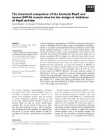
guide for the design of durable parking structures
Bạn đang xem bản rút gọn của tài liệu. Xem và tải ngay bản đầy đủ của tài liệu tại đây (3.02 MB, 40 trang )
Guide for the Design of Durable Parking
Structures
Reported by ACI Committee 362
Thomas
G.
Wei
l
Chairman
James C. Anderson
Michael L.
Brainerd
Ralph T. Brown
Debrethann
R.
Cagley
Girdhari
L. Chhabra
Anthony
P.
Chrest
Jo Coke
Thomas J.
D’
Arcy
Boris Dragunsky
David M.
Fertal
John
F.
Gibbons
Harald G.
Greve
Keith W. Jacobson
Norman
G. Jacobson, Jr.
Anthony N. Kojundic
Gerard
G.
Litvan
Howard R. May
Gerard
J. McGuire
This guide is a summary of practical information regarding design of park-
ing structures for durability. It also includes information about design
issues related to parking structure construction and maintenance
The guide is intended for use in establishing criteria for the design and
construction of concrete parking structures. It is written to specifically
address aspects of parking structures that are different from those of other
buildings or structures.
Keywords:
Concrete durability; construction; corrosion; curing; finishes;
freeze-thaw durability; maintenance; parking structures; post-tensioning;
precast concrete; prestressed concrete.
CONTENTS
Chapter l-General, p. 2
l.1-Introduction
1.2-Definition
of terms
1.3-Background
1.4-
Durability elements
ACI
Committee Reports, Guides, Standard Practices, and Com-
mentaries are intended for guidance in planning, designing, exe-
cuting, and inspecting construction. This document is intended
for the use of individuals who are competent to evaluate the
significance and limitations of its content and recommenda-
tions and who will accept responsibility for the application of the
material it contains. The American Concrete Institute disclaims
any and all responsibility for the stated principles.
The
Institute
shall not be liable for any loss or damage arising therefrom.
Reference to this document shall not be made in contract docu-
ments. If items found in this document are desired by the Archi-
tect/Engineer to be a part of the contract documents, they
shall be
restated
in mandatory language for incorporation by the Archi-
tect/Engineer.
Thomas
J. Downs
secretary
David C.
Monroe
Lewis
Y.
Ng
Carl A. Peterson
Suresh
G.
Pinjarkar
Predrag
L. Popovic
Robert L. Terpening
Ronald Van Der Meid
Carl H. Walker
Stewart C. Watson
Bertold E. Weinberg
Chapter
2-Structural
system, p. 8
2.l-Introduction
2.2-Factors in the choice of the structural system
2.3-
Performance characteristics of common construction types
2.4-
Performance characteristics of structural elements
2.5-Problem
areas
2.6-Below-grade structures
2.7-Multiuse
structures
Chapter 3-Durability and materials, p. 20
3.1-Introduction
3.2-Drainage
3.3-Concrete
3.4-Protection of embedded metals
3.5-Protection
of concrete
3.6-Guidelines for selection of durability systems for
floors and roofs
Chapter
4-Design
Issues related to construction
practice, p. 35
4.l-Introduction
4.2-Concrete cover
4.3-Vertical clearances for vehicles
4.4-Floor elevations for drainage
ACI 362.1R-97 became effective May 8,1997. This report supercedes ACI 362.1R94.
Copyright Q 2002, American Concrete Institute.
All rights reserved including rights of reproduction and use in any form or by any
means, including the making of copies by any photo process, or by electronic or
mechanical device, printed. written, or oral. or recording for sound or visual reproduc-
tion or for use in any knowledge or retrieval system or device. unless permission in
writing is obtained from the copyright proprietors.
362.1 R-l
(Reapproved 2002)
362.1R-2
ACI
COMMITTEE
REPORT
4.5-Materials
4.6-Placement and consolidation
4.7-Finishing
4.8-Curing
4.9-Reinforcement-Repair
of corrosion protection
4.10-Application
of sealers
4.11-Application
membranes
4.12-Specialty
concretes
4.13-Environmental
considerations
4.14-Field quality control
Chapter 5-Design issues related to maintenance prac-
tice, p. 37
5.1-Introduction
5.2-Suggested
minimum maintenance program
5.3-Fix
it now!!
Chapter 6-References, p. 38
6.1-Cited
references
6.2-Acknowledgment
CHAPTER l-GENERAL
l.l-Introduction
ACI
318 requires a general consideration of the dura-
bility of concrete structures. Because some concrete
parking structures have undergone significant deteriora-
tion, it is the purpose of this guide to provide specific
practical information regarding the design, construction,
and maintenance of parking structures with respect to
durability.
The guide is primarily concerned with those aspects of
parking structures that differentiate them from other
structures or buildings. Thus, the guide does not treat all
aspects of the structural design of parking structures.
1.2-Definition
of terms
Reference is made to the following selected terms to
help clarify the intent of the information provided
throughout the document. Unless otherwise noted, the
terms are as defined in
ACI
116R and are repeated here
for the convenience of the reader.
Admixture-A material other than water, aggregates,
hydraulic cement, and fiber reinforcement, used as an
ingredient of concrete or mortar, and added to the batch
immediately before or during its mixing.
Admixture, accelerating-An admixture that causes an
increase in the rate of hydration of the hydraulic cement,
and thus shortens the time of setting, or increases the
rate of strength development, or both.
Admixture, air-entraining-An admixture that causes
the development of a system of microscopic air bubbles
in the concrete, mortar, or cement paste during mixing.
Admixture, retarding-An admixture that causes a de-
crease in the rate of hydration of the hydraulic cement,
and lengthens the time of setting.
Admixture, water-reducing-An admixture that either
increases slump of freshly mixed mortar or concrete
without increasing water content or maintains slump with
a reduced amount of water, the effect being due to
factors other than air entrainment.
Admixture, high-range water-reducing-A water-re-
ducing admixture capable of producing large water reduc-
tion or great flowability without causing undue set retar-
dation or entrainment of air in mortar or concrete.
Air content-The volume of air voids in cement paste,
mortar, or concrete, exclusive of pore space in aggregate
particles, usually expressed as a percentage of total
volume of the paste, mortar, or concrete.
Air entrainment-The incorporation of air in the form
of minute bubbles (generally smaller than 1 mm) during
the mixiig of either concrete or mortar.
Air void-A space in cement paste, mortar, or con-
crete filled with air; an entrapped air void is char-
acteristically 1 mm or more in size and irregular in
shape; an entrained air void is typically between 10 pm
and 1 mm in diameter and spherical or nearly so.
Bleeding-The autogenous flow of mixing water with-
in, or its emergence from, newly placed concrete or mor-
tar; caused by the settlement of the solid materials within
the mass; also called water gain.
Bond-Adhesion and grip of concrete or mortar to
reinforcement or to other surfaces against which it is
placed, including friction due to shrinkage and longi-
tudinal shear in the concrete engaged by the bar defor-
mations; the adhesion of cement paste to aggregate.
Bond breaker-A material used to prevent adhesion
of newly placed concrete or sealants and the substrate.
Bonded member-A prestressed concrete member in
which the tendons are bonded to the concrete either
directly or through grouting.
Cast-in-place-Concrete which is deposited in the
place where it is required to harden as part of the
structure, as opposed to precast concrete.
Cementitious-Having cementing properties.
C.I.P Cast-in-place, referring to a method of con-
crete construction. See cast-in-place.
Chert-A very fine grained siliceous rock character-
ized by hardness and conchoidal fracture in dense varie-
ties, the fracture becoming splintery and the hardness
decreasing in porous varieties, and in a variety of colors;
it is composed of silica in the form of chalcedony,
cryp-
tocrystalline or microcrystalline quartz, or opal, or com-
binations of any of these.
Cold joint-A joint or discontinuity resulting from a
delay in placement of sufficient time to preclude a union
of the material in two successive lifts.
Composite construction-A type of construction using
members produced by combining different materials (e.g.,
concrete and structural steel), members produced by
combining cast-in-place and precast concrete, or
cast-in-
place concrete elements constructed in separate place-
ments but so interconnected that the combined compo-
nents act together as a single member and respond to
loads as a unit.
DESIGN OF PARKING STRUCTURES 362.1R-3
Concrete-A composite material that consists essen-
tially of a binding medium within which are embedded
particles or fragments of aggregate, usually a combination
of fine aggregate and coarse aggregate; in portland-
cement concrete, the binder is a mixture of portland
cement and water.
Concrete, precast-Concrete cast elsewhere than its
final
position.
Concrete, prestressed-Concrete in which internal
stresses of such magnitude and distribution are intro-
duced that the tensile stresses resulting from the service
loads are counteracted to a desired degree; in reinforced
concrete the prestress is commonly introduced by ten-
sioning the tendons.
Construction joint-The surface where two successive
placements of concrete meet, across which it may be de-
sirable to achieve bond and through which reinforcement
may be continuous.
Contraction joint-Formed, sawed, or tooled groove
in a concrete structure to create a weakened plane and
regulate the location of cracking resulting from the
dimensional change of different parts of the structure.
Control joint-See contraction joint.
Corrosion-Destruction of metal by chemical, electro-
chemical, or electrolytic reaction with its environment.
Corrosion inhibitor-A chemical compound, either
liquid or powder, that effectively decreases corrosion of
steel reinforcement before being imbedded in concrete,
or in hardened concrete if introduced, usually in very
small concentrations, as an admixture.
Crack-A complete or incomplete separation, of
either concrete or masonry, into two or more parts
produced by breaking or fracturing.
Crack-control reinforcement-Reinforcement in con-
crete construction designed to prevent openings of
cracks, often effective in limiting them to uniformly
distributed small cracks.
Creep-Time-dependent deformation due to sustained
load.
Deformed bar-A reinforcing bar with a manufactured
pattern of surface ridges intended to prevent slip when
the bar is embedded in concrete.
Deicer-A chemical such as sodium or calcium chlor-
ide, used to melt ice or snow on slabs and pavements,
such melting being due to depression of the freezing
point.
Delamination-A separation along a plane parallel to
a surface as in the separation of a coating from a sub-
strate or the layers of a coating from each other, or in
the case of a concrete slab, a horizontal splitting,
cracking, or separation of a slab in a plane roughly
parallel to, and generally near, the upper surface; found
most frequently in bridge decks and caused by the corro-
sion of reinforcing steel or freezing and thawing, similar
to spalling, scaling, or peeling except that delamination
affects large areas and can often only be detected by
tapping.
Double-tee-A precast concrete member composed of
two stems and a combined top flange.
Elastic design-A method of analysis in which the de-
sign of a member is based
on a linear stress-strain rela-
tionship and corresponding limiting elastic properties of
the material.
Elastic shortening-In prestressed concrete, the
shortening of a member that occurs immediately on the
application of forces induced by prestressing.
Expansion joint-A separation provided between ad-
joining parts of a structure to allow movement where
expansion is likely to exceed contraction.
Flat plate-A flat slab without column capitals or drop
panels (see also flat slab).
Flat slab
-A
concrete slab reinforced in two or more
directions and having drop panels or column capitals or
both (see also flat plate).
Fly ash-The finely divided residue resulting from the
combustion of ground or powdered coal and which is
transported from the
firebox
through the boiler by flue
gases.
Isolation joint-A separation between’adjoining parts
of a concrete structure, usually a vertical plane, at a
designed location such as to interfere least with perfor-
mance of the structure, yet such as to allow relative
movement in three directions and avoid formation of
cracks elsewhere in the concrete and through which all or
part of the bonded reinforcement is interrupted (see also
contraction joint and expansion joint).
Joint sealant-Compressible material used to exclude
water and solid foreign materials from joints.
Jointer (concrete)-A metal tool about 6 in. (150 mm)
long and from 2 to 4
1
/
2
in. (50 to 100 mm) wide and hav-
ing shallow, medium, or deep bits (cutting edges) ranging
from
31~~
to
J/
in. (5 to 20 mm) or deeper used to cut a
joint partly through fresh concrete.
Nonprestressed reinforcement-Reinforcing steel, not
subjected to either pretensioning or post-tensioning.
Plastic cracking-Cracking that occurs in the surface
of fresh concrete soon after it is placed and while it is
still plastic.
Plastic shrinkage cracks-see plastic cracking.
Post-tensioning-A method of prestressing reinforced
concrete in which tendons are tensioned after the con-
crete has hardened.
Pour strip-A defined area of field-placed concrete
used to provide access to embedments, improve tolerance
control between adjacent elements, or enhance drainage
lines. Pour strips are typically associated with pretopped,
prestressed structures but may be utilized with other
structural types as well (not defined in
ACI
116R).
Precast-A concrete member that is cast and cured in
other than its
final
position; the process of placing and
finishing precast concrete (see also cast-in-place).
Prestress-To
place a hardened concrete member or
an assembly of units in a state of compression prior to
application of service loads, the stress developed by
prestressing, such as pretensioning or post-tensioning (see
also concrete, prestressed; prestressing steel; preten-
362.1R-4
ACI
COMMITTEE
REPORT
sioning; and post-tensioning).
Prestressed concrete See
concrete, prestressed.
Prestressing steel-High-strength steel used to pre-
stress concrete, commonly seven-wire strands, single
wires, bars, rods, or groups of wires or strands (see also
prestressed; concrete, prestressed; pretensioning, and
post-tensioning).
Pretensioning-A method of prestressing reinforced
concrete in which the tendons are tensioned before the
concrete has hardened.
Pretopped-A term for describing the increased flange
thickness of a manufactured precast concrete member
(most commonly a double-tee beam) provided in the
place of a field-placed concrete topping. (Definition by
ACI
362.)
Rebar-Colloquial term for reinforcing bar (see rein-
forcement).
Reinforcement-Bars, wires, strands, or other slender
members embedded in concrete in such a manner that
they and the concrete act together in resisting forces.
Retarder-An admixture that delays the setting of
cement paste, and hence of mixtures such as mortar or
concrete containing cement.
Saturation-(l) in general: the condition of coexis-
tence in stable equilibrium of either a vapor and a liquid
or a vapor and solid phase of the same substance at the
same temperature; (2) as applied to aggregate or con-
crete, the condition such that no more liquid can be held
or placed within it.
Screeding-The
operation of forming a surface by the
use of screed guides and a strikeoff.
Shrinkage-Decrease in either length or volume.
Shrinkage, drying Shrinkage resulting from loss of
moisture.
Shrinkage, plastic-Shrinkage that takes place before
cement paste, mortar, grout, or concrete sets.
SI (Systeme International)-The modern metric
system; see ASTM E 380.
Silica fume-Very fine noncrystalline silica produced
in electric arc furnaces as a byproduct of elemental sil-
icon or alloys containing silicon; also is known as con-
densed silica
fume and microsilica.
Slab-A flat, horizontal or nearly so, molded layer of
plain or reinforced concrete, usually of uniform but
sometimes of variable thickness, either on the ground or
supported by beams, columns, walls, or other framework.
Spall-A fragment, usually in the shape of a flake, de-
tached from a larger mass by a blow, by the action of
weather, by pressure, or by expansion within the larger
mass; a small spall involves a roughly circular depression
not greater than 20 mm in depth nor 150 mm in any
dimension; a large spall, that may be roughly circular or
oval or in some cases elongated, is more than 20 mm in
depth and 150 mm in greatest dimension.
Spalling-The development of spalls.
Span-Distance between the support reactions of
members carrying transverse loads.
Span-depth ratio-The numerical ratio of total span
to member depth.
Stirrup-A reinforcement used to resist shear and
diagonal tension stresses in a structural member, typically
a steel bar bent into a U or box shape and installed per-
pendicular to or at an angle to the longitudinal rein-
forcement formed of individual units, open or closed, or
of continuously wound reinforcement. Note
-
the term
“stirrups” is usually applied to lateral reinforcement in
flexural
members and the term “ties” to lateral reinforce-
ment in vertical compression members (see also tie).
Strand-A prestressing tendon composed of a number
of wires twisted about center wire or core.
Superplasticizer-See admixture, high-range
water-
reducing.
Tie-(l) loop of reinforcing bars encircling the longi-
tudinal steel in columns; (2) a tensile unit adapted to
holding concrete forms secure against the lateral pressure
of unhardened concrete.
Tooled joint-A groove tooled into fresh concrete with
a concrete jointer tool to control the location of shrink-
age cracks. See contraction joint.
Unbended post-tensioning-Post-tensioning in which
the post-tensioning tendons are not bonded to the sur-
rounding concrete.
Unbended tendon-A tendon that is permanently pre-
vented from bonding to the concrete after stressing.
Water-cement ratio-The ratio of the amount of
water, exclusive only of that absorbed by the aggregates,
to the amount of cement in a concrete, mortar, grout, or
cement paste mixture; preferably stated as a decimal by
mass and abbreviated
w/c.
Water-cementitious material
ratio-The
ratio of the
amount of water, exclusive only of that absorbed by the
aggregate, to the amount of cementitious material in a
concrete or mortar mixture.
w/c-See water-cement ratio and water-cementitious
ratio.
Yield
strength-The stress, less than the maximum
attainable stress, at which the ratio of stress to strain has
dropped well below its value at low stresses, or at which
a material exhibits a specified limiting deviation from the
usual proportionality of stress to strain.
1.3-Background
Parking structures are built either as independent,
free-standing structures or as integral parts of multi-use
structures. Parking structures may be above grade, at
grade, or partially or fully below grade.
Many different terms are used to describe parking
structures. Some of the common terms include garage,
parking garage, parking deck, parking ramp, parking
structure, parking facility, multilevel parking deck, and
open parking structure. This guide uses the general term
“parking structure.”
1.3.1
Differences
from other structures-The open
parking structure (defined in various building codes as
having a large percentage of the facade open) is sub-
jected, in varying degrees, to ambient weather conditions.
DESIGN OF PARKING STRUCTURES
362.1R-5
Similarly, a completely enclosed parking structure is often
ventilated with untempered outside air. Frequently, park-
ing structures are very large in plan compared to most
enclosed structures. They are exposed to seasonal and
daily ambient temperature variations. These temperature
variations result in greater volume change effects than
enclosed structures experience. Restraint of volume
changes can create cracking of floor slabs, beams, and
columns, which, if unprotected, may allow rapid ingress
of water and chlorides, leading to deterioration.
The primary live loads are moving and parked vehi-
cles. For roof levels, consideration is frequently given to
some combination of vehicular and roof loads (water or
snow). At barrier walls or parapets some building codes
typically require consideration of a lateral bumper load.
Similar to a bridge deck, a parking structure is
exposed to weather. The roof level is exposed to precipi-
tation, solar heating, ultraviolet, infrared radiation, and
chemicals carried by wind and precipitation.
The edges of an open parking structure may be subject
to the same weather conditions as the roof, and other
areas may experience runoff from the roof. All floors are
subject to moisture in the form of water or snow carried
in on the undersides of vehicles, as shown in Fig. 1.1.
This moisture may contain deicing salts in some climates.
Unlike a bridge deck, the lower levels of a parking
structure are not rinsed with rain. The structure’s expo-
sure to chlorides may be increased due to poor drainage
of the slab surface. In marine areas, salt spray, salt-laden
air, salty sand, and high-moisture conditions can produce
serious corrosion.
1.4-Durability
elements
The
durability of parking structures is related to many
factors, including weather, the use of deicer salts, con-
crete materials, concrete cover over reinforcement, drain-
age, design and construction practices, and the response
of the structural system to loads and volume change. See
Table 1.1 for common durability problems.
The most common types of deterioration and unde-
sirable performance of parking structures are due to
corrosion of reinforcement, freezing and thawing,
cracking, ponding of water, and water penetration. In
climates where deicer salts are used, symptoms of deter-
ioration may include: spalls and delaminations in the
driving surface, leakage of water through joints and
cracks, rust staining, scaling of the top surface, and
spalling of concrete on slab bottoms, beams, and other
underlying concrete elements. Even walls and columns
suffer distress from leakage, splash, and spray of salt-con-
taminated water. The lives of parking structures have
been shortened by the same effects as described in
NCHRP 57
Durability of Concrete Bridge Decks.
Even in climates where deicers are not used, water
penetration through parking structure floors is often
perceived as poor performance. In parking structure
floors located over enclosed retail, office space, or other
occupied space, water penetration through the slab or
Fig. 1.1-Deicing salt-bearing slush brought into structure
in car wheel well
deck is objectionable.
1.4.1
Corrosion of embedded metal
1.4.1.1 Reinforcement-The electrochemical mech-
anism of chloride-induced corrosion of steel embedded
in concrete is complex and continues to be studied. The
high alkalinity of concrete inhibits corrosion of steel
embedded in sound, dense concrete by forming a protec-
tive ferric oxide layer on the steel surface. Water-soluble
chloride ions can penetrate and undermine this protec-
tive layer, decrease the electrical resistivity of the con-
crete, and establish electrical potential differences. These
changes, in the presence of sufficient moisture and
oxygen, promote corrosion of the steel.
When corrosion does occur, the resulting expansion
frequently causes fracturing and spalling of the concrete.
If the fracture extends to the concrete surface, it appears
as a feather-edged fracture surface or spall, similar to
that shown in Fig. 1.2.
When closely spaced reinforcement in a slab corrodes,
horizontal fractures may occur that are not visible at the
surface. These subsurface fractures may create one or
more delaminations at the various reinforcement levels
(Fig. 1.3 and 1.4).
Repeated traffic, freeze-thaw damage, or both, may
dislodge the concrete above the delamination. With time,
the loose material is lost, resulting in a spall or pothole
(Fig. 1.3 and 1.5). Spalls can be hazardous to pedestrians
and vehicular traffic as well as being detrimental to
structural integrity. Spalls can be caused by corrosion of
reinforcement, severe damage due to freezing and thaw-
ing, concentrated forces at bearing points and connec-
tions, or a combination of these factors.
Without effective protection, corrosion of reinforce-
ment frequently occurs on bridges and parking structures.
The source of chlorides is commonly deicer salts in
northern sites and saltwater spray or salt laden air near
oceans. Chlorides may also be placed in the concrete
during construction in the form of admixtures or as
constituents of the concrete mix.
Chloride ion content versus depth from the surface of
362.1R-6
ACI COMMITTEE REPORT
Table 1.1
-
Potential durability problems
Potential problem area
Cracking (1.3.3)-Cracking can be controlled but not
prevented
100
percent
Leaking (1.3.3)
Action to be taken to prevent or minimize the problem
(guide section)
l
Choice of structural system has significant influence
(2.3-2.5,
3.5.2.5)
l
Design for volume change (2.51)
a
Drainage (3.2.2)
l
See cracking (3.5.2.5)
l
Install and maintain joint sealant and isolation joint seals (3.5.2)
Freeze/thaw (scaling) (1.3.2)
l
Air entrainment (3.3.3.4)
0
Drainage (3.2)
0
Protective coatings (3.5.1)
Corrosion (1.3.1)
0
Drainage (3.2)
0
Quality concrete (3.3)
0
Concrete cover (3.4.1)
l
Protection of reinforcement (3.4.2)
0
Protective coatings (3.5.1)
a
Other embedded metals (3.4.3)
0
Silica fume (3.3.3.3)
l
Corrosion inhibitors (3.4.4)
0
Dampproofing
admixture (3.4.5)
l
Cathodic protection (3.4.6)
Low quality concrete
0
Water-cement ratio (3.3.3.1)
0
Air entrainment (3.3.3.4)
0
Admixtures (3.3.3.5)
0
Finishing (3.3.4)
l
Curing (3.3.4.2)
TOP OF CONCRETE
f
f
ICE LENSES MAY
WEARING SURFACE
FORM IN CRACK
BY-PRODUCTS
Fig.
1.2-Spa11
due to corrosion of
exposed
steel (excerpted
from NCHRP Synthesis 4)
a parking structure can be as high as the levels shown in
Fig. 1.6, in regions where deicing salts are used. The core
shown in the figure is from an unprotected 13-year-old
concrete slab located in a corrosive environment. Chlor-
ide ion contents of concrete are reported in various ways:
(1) percent by weight of cement, (2) percent by weight of
concrete, (3) pounds per cubic yard of concrete, and (4)
parts per million of concrete. Conversion among the four
reporting methods requires knowledge of the cement
content of the concrete and the concrete unit weight.
The maximum water-soluble chloride ion content in the
hardened concrete at ages from 28 to 42 days
recom-
DELAMINATION
Fig. 1.3-Schematic of delamination and pothole in
flat
slab construction
mended by
ACI
318 is 0.06 percent and 0.15 percent by
weight of cement, respectively, for prestressed and
non-
prestressed reinforced concrete. It is generally believed
that the corrosion threshold is a chloride ion content of
0.2 percent by weight of cement. In a normal weight con-
crete containing 564 lbs. of
cementEyd3,
this equates to
1.1
lb&d3,
280 ppm, or 0.028 percent by weight of con-
crete. See NCHRP 57, Durability of Concrete Bridge
Decks,
for conversion factors expressing chloride content.
Corrosion can occur in
uncracked
concrete due to
362.1 R-7
Fig.
1.4-Core
showing top
delaminations
chloride ions, moisture, and oxygen permeating into the
concrete (see Section 3.3.3.1). However, corrosion of
reinforcement is generally more severe and begins earlier
at cracks and places where water can easily penetrate.
Information on corrosion of metals in concrete is avail-
able in
ACI
222R,
Corrosion of Metals in Concrete.
1.4.1.2 Bonded prestressing steel-The corrosion of
prestressing strand in pretensioned double-tees and
inverted tee-beams used in parking structures has nor-
mally occurred where there is a breach in the sealed
joints and where brackish water reaches the bottoms of
members.
Corrosion of grouted, prestressing steel has occurred
where the grout did not encase the wires, bar, or strand
within a grout duct, and moisture or chlorides gained
access to the open void.
1.4.1.3 Unbonded prestressing steel-Most cases of
corrosion of unbonded prestressing steel in parking struc-
tures have involved either natural saltwater or deicer salt
exposure to loosely sheathed systems with inadequate
amounts of grease. Other areas most
susceptible
to cor-
rosion include poorly grouted stressing end anchorages,
intermediate stressing points at construction joints, and
regions of insufficient concrete cover.
1.4.1.4 Other embedded metals-Corroded electrical
conduits have been observed in structures exposed to
deicer salts. Likewise, uncoated aluminum has been ob-
served to corrode in concrete containing chloride and
particularly where the aluminum has been in contact with
the steel reinforcement. Embedded metals of all kinds
should be specifically reviewed for their durability and
function.
1.4.2
Freezing and thawing damage-Scaling
of con-
crete is a deterioration observed in parking structures
Fig.
1.5-Potholes
in floor
surface
SOLUBLE CHLORIDEION CONTENT
(LBS.
a-
PERCU. YD.)
0
IO
20
30
F
CHLORIDE ION
3
3.
IN CONCRETE
E
2
j
I
0
-’
APPROXIMATE
THRESHOLD
IO.
:
I
i
Cp&
Fig. 1.6-Chloride ion content of concrete versus depth
exposed to a freezing and thawing environment. Cyclic
freezing and deicer scaling is discussed extensively in
ACI
201.2R
Guide to Durable Concrete. The phenomenon
usually begins with the loss of thin flakes at the surface.
As deterioration progresses, coarse aggregates may be ex-
posed. In advanced stages, the surface may progress from
362.1 R-8
ACI
COMMITTEE REPORT
Fig. 1.7-Scaling of floor surface
Fig.
1.8-Spalling
of beam
soffit
beside leaking isolation
joint
an exposed aggregate appearance to that of rubble. Fre-
quently, with prolonged water saturation and repeated
freeze-thaw cycles, the concrete will develop fine cracks
paralleling the exposed surface. The presence of deicers
will accelerate this deterioration (Fig. 1.7).
The addition of air entrainment is the most effective
method of increasing the resistance of concrete to
damage due to freezing and
thawing
.
The entrained
air-
void size and spacing in. the concrete is also important
(see
ACI
345R).
S
evereabrasion accelerates the deter-
ioration of concrete undergoing scaling. Good drainage
(pitch of surface to drains) diminishes the severity of
freezing and thawing exposure by reducing the moisture
content of the concrete.
1.4.3 Cracking and water penetration-Cracking of
concrete exists in many forms. Some common types are:
microcracking, partial depth cracks in the top of mem-
bers, and through-slab cracks. Observations of parking
structures suggest that corrosion will occur earlier and is
much more likely at wide cracks than at untracked or
finely cracked areas. For information on resistance to
cracking, see Section 3.5.2.5.
In addition to abetting corrosion, water penetration
through the slab is undesirable. When substantial
amounts of water penetrate completely through the slab
at cracks and joints, corrosion and freeze-thaw damage
of the sides or bottoms of underlying members may
occur. Damage to ribs, joists, webs, beams, columns,
heavily loaded joints, and bearings is more critical to
structural integrity than damage to the slab because these
elements support larger tributary areas. Severe damage
to a beam at an isolation joint is shown in Fig. 1.8.
The potential problems and actions that may be taken
to reduce or eliminate the problem are listed in Table
1.1. The action portion of the list references the sec-
tion(s) of the text that discuss the action or problem.
CHAPTER
2-STRUCTURAL
SYSTEMS
The selection and design of a structural system for a
parking structure involve making choices from many con-
struction methods and materials. Other considerations
affecting the design include the site, functional require-
ments, economics, appearance, performance for the pur-
pose intended, durability, and building code requirements
relating to strength and safety. This chapter examines the
preceding factors and how they may affect the perfor-
mance and durability of the structural system of a
parking structure.
2.2-Factors in the choice of the structural system
2.2.1
Site-Geographic location and site selection will
influence architectural and structural planning. Antici-
pated temperature and humidity ranges, and the proba-
bility of a corrosive environment, should be evaluated
during the design process to determine what protective
measures should be incorporated into the design.
2.2.2 Functional requirements
-Complete functional
design of a parking facility is not within the scope of this
guide, but a limited review is necessary to discuss the
DESIGN OF PARKING STRUCTURES 362.1R-9
selection of a structural system. In general, the structure
should easily accommodate both vehicles and people.
The functional design of the facility should consider
various elements such as parking stall and aisle dimen-
sions, ramp slopes, turning radii, traffic flow patterns,
means of egress, security features,. and parking control
equipment. Some or all of these factors may affect the
layout of columns, depth of structural members, and the
design of the structural system.
2.2.3
Economics-Construction
cost is an important
factor in selecting the structural system. The structural
system must provide the needed level of durability, func-
tion, and aesthetics to be perceived as economical. In-
clusion of one or more of the various available protection
systems, in and of itself, however, will not adequately
address the importance of structural system economics.
2.2.4 Aesthetic
treatment-Aesthetics
are not within the
scope of this guide. However, parking structures are
often designed so that a structural element serves a
significant architectural function as well. For example, an
exterior beam may be designed to carry gravity loads,
barrier loads, and lateral loads. But, if exposed to view,
it may also affect the aesthetics of the building. Further,
the functional design may require sloping floors, but hori-
zontal elements may be preferred at the building exterior
for aesthetic reasons. These considerations may affect the
choice of structural systems and the exterior framing.
2.2.5 Building
code
requirements-Requirements of
model and local building codes vary. They affect:
0
0
a
0
l
tion
l
0
l
0
Structural design and loading criteria
Fire resistance
Barrier requirements
Ventilation requirements
Height and area limits related to type of
construc-
Ramp slope limits
Perimeter openness requirements
Headroom clearance requirements
Means of egress
2.2.5.1 Gravity loads-Building codes commonly re-
quire a uniformly distributedload of 50 psf or a 2000 lb
concentrated wheel load (whichever is more critical)
anywhere on a floor (whichever is more critical), with
additional load for snow (see 2.2.5.2) on the top level.
Some codes require that the size of the concentrated
wheel load tread print be 20 square in. (Fig. 2.1). Most
codes require designing members for the worst case
among several patterned load cases. Typically, slabs are
designed for bending and punching shear due to wheel
loads.
The use of reduced live loads is usually appropriate,
where allowed by code or permitted by appeal, since
actual automobile loads in fully loaded parking structures
seldom exceed 30 psf. However, added reserve capacity
in design may be desirable to account for future in-
creased loadings due to added material such as overlays
used in repair. Unusual loads due to fire trucks, other
Fig. 2.1-Imprint of wheel
loads
special equipment, soil, and planter boxes require design
consideration.
2.3.5.3 Snow/live
bad
combination-Many model or
local building codes require consideration of roof loads
(usually snow) in addition to the normal vehicular loads.
Simple addition of vehicular and snow loads may be too
conservative for the elastic design of principal members.
For example, the required load may be
50
psf for parking
plus 30 psf for snow, resulting in a design load of
80
psf.
The estimated actual load, if cars and snow are on the
deck at the same time and no supplemental uniform load
such as an overlay is added, probably would not exceed
30 psf (maximum) for cars plus 30 psf for snow for a
total of 60 psf. Thus the probability of maximum snow
loads exceeding code requirements is unlikely, even when
vehicular loading is at its maximum.
The committee recommends designing the structure to
support the following load combinations:
a) Strength design for
unreduced
vehicular load and
snow (that is,
50
psf + snow) at roof level. For
example:
1.4D
+
1.7L
+
1.2S
b) Serviceability check on load combination of
reduced vehicular load and snow at roof level.
For example: D +
0.6L
+ S
2.2.5.3
Wind
loads-Parking structures and their
components should be designed to resist the design wind
pressures indicated in the applicable building codes.
Model building codes have methods with which to calcu-
late wind pressures using basic wind speed, importance
factor, exposure factor, and projected areas.
The building facade should be considered solid unless
a rigorous analysis is made for the effective wind pres-
sure on the members exposed to wind or if the applicable
code requires a different approach.
2.2.5.4 Seismic loads-Continuously ramped floors
commonly found in parking structures complicate the
lateral force analysis (see Section 2.5.3).
The ramp slabs,
cast-in-place or precast, must be able to support the
seismic bending and shear forces.
If seismic loading is required by the local building
code, the seismic loading case should be checked to see
362.1R-10
\CAST-IN-PLACE
SLAB
PLAN VIEW
Fig. 2.2-Plan at transfer girder
whether it or wind load governs. In seismic regions,
proportions and details required for earthquake resis-
tance must be provided even if wind forces govern.
ACI
318 (Chapter 21) and the Building Seismic Safety Council
Recommended Provision for Seismic Design Requirements
for Buildings
are excellent sources of information for use
with the local building code.
2.2.5.5
Barrier
loads-Few
model and local building
codes prescribe lateral load requirements for vehicle
barriers at the perimeter of floors. The design objective
is to resist the load of a slow-moving vehicle. In its
Suggested Building Code Provisions for Open Parking
Structures, The Parking Consultants Council of the
National Parking Association recommends a single
horizontal ultimate load of 10,000 lb. One of the highest
concentrated, lateral forces required on a barrier is
12,000 lb (City of Houston, Texas, Building Code). The
South Florida Building Code requires that the barrier
load be applied 27 in. above the floor. Other building
codes require barrier type curbs and energy-absorbing
capability at the perimeter of the floor. Curbs or wheel
stops alone are usually not considered effective barriers
against moving vehicles.
In the absence of a local building code that prescribes
lateral vehicular load requirements, the committee
recommends the National Parking Association single hor-
izontal ultimate load of 10,000 lb, distributed over a l-ft-
square area applied at a height of 18 in. above the adja-
cent surface at any point along the structure.
2.3-Performance
characteristics of common construc-
tion types
Selection of a structural system should include con-
sideration of those performance characteristics that are
applicable to parking structures. Structural systems for
parking structures require more attention to durability
than do weather-protected structural systems. Vibration
under moving loads should be checked during system
selection; see
PCI
Design Handbook, Chapter 9 for guid-
ance. Since many free-standing parking structures are
constructed of precast prestressed concrete or
cast-in-
place post-tensioned concrete, detailed design infor-
mation for these structural types may be obtained from
the Pecast/Prestressed Concrete Institute and the
Post-
Tensioning Institute. See Chapter
6-References.
2.3.1 Cast-in-place (CIP) concrete construction
2.3.1.1 Post-tensioned CIP Construction-Post-
tensioning introduces forces and stresses into a structure
in addition to those induced by gravity and applied loads.
The post-tensioning forces are used to counteract gravity
loads, reduce tensile stresses, and reduce cracking.
Post-tensioned spans may be longer for a given mem-
ber size, or the members may be smaller for a given
span, compared to concrete with nonprestressed rein-
forcement. It is not necessary, or even desirable, to
design the post-tensioned reinforcement to carry all the
gravity loads.
The quantity of post-tensioning included in the struc-
ture is based on the required structural capacity and the
serviceability
requirements. Generally, the post-tensioning
will balance a portion of the dead loads (less than 100
percent) and will provide the minimum precompression
indicated in Table 3.2. Precompression in excess of 300
psi for slabs or 500 psi for beams, and balancing more
than 100 percent of the dead load should generally be
avoided as this may result in undesirable cambers, addi-
tional cracking, and increased volume changes.
In addition to the drying shrinkage and temperature
movements that affect all concrete structures, post-ten-
sioning introduces volume changes due to elastic short-
ening and creep which must be accounted for in the
design.
Post-tensioning a structure reduces cracking; however,
if cracks do occur, they tend to be larger than those
found in concrete structures reinforced with nonpre-
stressed reinforcement. Providing additional nonpre-
stressed reinforcement in areas where cracks are likely to
occur has proven effective in controlling the size of
cracks.
The cracks shown in Fig. 2.2, which run parallel to the
transfer girder, are common. These cracks are most likely
the result of tensile stresses caused by flexure in the top
of the slab at the girder. Additional nonprestressed rein-
forcement in the slab will help control this type of
cracking.
Adequately detailed, manufactured, and installed
un-
bonded tendons include protection of the prestressing
steel against corrosion. The latter is usually accomplished
by placing the prestressing steel in a sheathing filled with
grease. The Post-Tensioning Institute has developed and
publishes specifications entitled Specifications for
Un-
bonded Single Strand Tendons.
The
stressing pockets
should be fully grouted to protect the anchorage devices
and ends of tendons from moisture. Special care is
needed to avoid the creation of a path at the interface
between steel and grout permitting water to penetrate to
the anchorage. In corrosive environments, the referenced
PTI specification has stringent requirements for
encap-
362.1R-11
sulation of the tendon. Effective sealants, coatings, or
bonding agents should be considered for added protec-
tion against water penetration at pockets (see Fig. 2.3).
Sealant installed at each construction joint will
minimize water penetration through slabs, if properly
installed and maintained (see Section 3.5.2.). At closure
strips, tendons should be cut off and the anchorage
protected before closure concrete is placed.
2.3.1.2
Nonprestressed
CIP construction-Perfor-
mance under conditions of vehicle-induced vibrations is
generally good in reinforced CIP concrete structures with
nonprestressed reinforcement.
Although no direct relationship between crack width
and corrosion has been established, the committee’s
experience indicates that corrosion is frequently found in
negative moment areas where
flexural
cracking has
occurred. One method of reducing crack width is to in-
crease the amount of reinforcement in the negative
moment area. This reduces the steel stress and reduces
the
Z
factor
(ACI
318). The application of this concept
requires engineering judgment in setting maximum values
for steel stress or minimum values for
Z
factor. Some
designers choose a maximum dead load steel stress of
15,000 psi or keep the
Z
factor as low as
55.
The PCI
Design Handbook illustrates a method that uses recom-
mended maximum values for the
Z
factor.
The corrosion resistance of nonprestressed CIP
systems can be increased by taking one or more of the
following measures:
increase concrete cover, add a
concrete overlay, coat nonprestressed reinforcement with
epoxy, apply traffic bearing membranes, reduce concrete
permeability, or use a corrosion inhibitor.
2.3.2 Precast/prestressed concrete construction-Precast
concrete members are typically manufactured with close
dimensional tolerances. However, the design of a precast
parking structure should provide for adequate casting
and assembly tolerances. Units should not be forced into
position during erection. Stresses developed by forced
fitting can cause localized failure. Coordination of drains,
expansion joints, blockouts, and embedded items is
necessary to properly detail such structures. Member
deflections and cambers are important and should be
considered.
Correct detailing of connections between precast
members is critical to achieving good performance.
Because parking structures are typically exposed to the
full range of temperature extremes, connections should
not be too rigid. Because connections may be exposed to
water through leaking joints or blowing rain, the exposed
components should be protected. In corrosive environ-
ments, epoxy-coated, hot-dipped galvanized, or stainless
steel may be used to reduce metal corrosion.
Field-
applied coatings may also be used to protect exposed
welds and plates. The effectiveness of field-applied
coatings is directly related to the thoroughness of surface
preparation.
The
PCI Design Handbook, PCI Connection Manual,
and
PCI’s
Parking Structures: Recommended Practice
for
P/T
ANCHOf3
CONTINUOUS ANCHOR
BAR
(TYP)
P/T
POCKET: COAT WITH
BONDING
AGENT, FILL WITH NUN-SHRINK
GROUT.
Fig.
2.3-P/T
end anchorage detail
the Design and Construction
cover many topics helpful in
the design of precast prestressed parking structures.
Proper pretensioning reduces service load cracks, thus
reducing the rate of water penetration into or through
the member. Pretensioned concrete units have already
undergone full elastic shortening prior to erection; how-
ever, the effects of temperature, long-term creep, and
shrinkage of pretensioned members after erection should
be considered, as indicated
in
Table 2.1.
2.3.3 Structural steel construction-Cast-in-place or
precast concrete has been combined with structural steel
framing for parking structures. Stay-in-place metal deck
forms and other exposed steel
wiIl
not perform well in
areas where deicing salts are used or where there is
airborne chloride unless the steel is protected with
special coatings. Exposed steel framing should be treated
with a weather-resistant, anti-corrosion coating. Joints
between the steel and concrete should be adequately
sealed to minimize moisture penetration.
2.3.4
Other
performance
considerations
2.3.4.1 Drainage-For a detailed discussion of
drainage considerations, see Chapter 3. In general, CIP
construction simplifies design for good drainage because
variations in slope can be easily accommodated. Concrete
topping placed over precast construction allows sloping
of the CIP topping for drainage. Pretopped precast mem-
bers can be sloped in two directions, but may crack if
twisted excessively. The amount of torsion a member can
tolerate without cracking depends on several factors that
include length and cross section dimensions. For exam-
ple, many pretopped double-tees with a
60-ft
span will
develop torsional cracking when the ends have a differ-
ential slope greater than approximately 1 percent.
Dif-
ferential slope is the difference in slope between
transverse lines across the top of each end of the
double-
tee. Therefore, in some cases, proper drainage
slopes
may require the use of field-applied topping in limited
areas of the structure.
362.1 R-12
ACI
COMMITTEE
REPORT
SLOPE END BAY
-7
Fig. 2.4-Longitudinal section
Fig.
2.5-Waffle
slab
.;
1,
Fig. 2.6-Cast-in-place slab (not shown) on precast
joists
on inverted tee beams
2.3.4.2 Lateral load
resistance-Moment-resisting
frames are used in monolithic CIP structures to accom-
modate lateral loads. It is typical for every column line to
provide such a frame, resulting in a distribution of lateral
forces.
The segmental nature of precast concrete and its flex-
ibility often require the use of connections that are
simple and permit rotation. Precast structures normally
have selected column lines with moment-resistant frames
or shear-walls to resist lateral forces.
Lateral force resistance may be provided by frames,
walls, and columns fixed to foundations. In certain cases,
sloped floors may be used as truss elements (see Fig.
2.4).
2.4-Performance
characteristics of structural elements
2.4.1 CIP
floor
systems
with thin slabs
2.4.1.1 CIP
systems
with nonprestressed thin
slabs-
Thin
slab systems, such as waffle slabs (Fig. 2.5) and pan
joists may require less concrete than one-way slab de-
signs. These systems involve slabs of 4 in. or less in
thickness, stiffened by ribs or joists underneath.
Waffle slabs and pan joists typically develop through-
slab cracking and may require special waterproofing and
durability measures. Through-slab cracks can be expected
to occur in these systems due to differential shrinkage
between slab and joist.
Flexural
cracks in the negative
moment region are also likely to fully penetrate thin
slabs. The cracks permit water to reach the reinforce-
ment, causing leaching on the underside and corrosion of
unprotected reinforcement. Crack control using sealed
joints is generally not practical for cast-in-place thin
slabs.
An example of a composite system with thin slab char-
acteristics is one that incorporates precast pretensioned
joists spaced up to 8 ft-8 in. on centers and spanning 40
to 64 ft, and supporting a nominal
4-in.
slab (see Fig.
2.6).
Waffle slabs, pan joists, cast-in void systems, and
untopped hollow-core systems typically do not perform
well in parking structures. Added protection such as
vehicular trafficmembranes, epoxy-coatednonprestressed
reinforcement bars and other protective measures should
be considered (see Table 3.1).
Prestressed hollow-core units with topping (Fig. 2.7)
behave like the thin-slab systems described previously
and usually have higher deflections. The effects of elastic
deflection and creep deflection on drainage should be
considered. Weep holes in the downslope core ends will
help drain condensation and water that may accumulate
DESIGN OF PARKING STRUCTURES 362.1R-13
Fig. 2.7-Cast-in-place topping (not shown) on precast
hollow core units
inside the cores.
One-way and two-way slab systems with nonpre-
stressed reinforcement
wilI
generally produce visible
cracks at supports due to flexure. When subjected to
restraint of volume change forces, these cracks may pene-
trate the entire slab.
2.4.1.2
CIP systems with post-tensioned thin slabs-
CIP post-tensioned joists or precast pretensioned joists
with post-tensioned slabs have been used in parking
structures. These systems often have large span-to-depth
ratios as compared to other structural systems.
2.4.2
CIP thick-slab f
loor
Systems-Two-way thick slab
systems without drop panels are called flat plate slabs.
Those with drop panels or column capitals are flat slabs.
These slabs can be conventionally reinforced or
post-
tensioned.
In flat slab or flat plate construction (Fig.
2.8),
the
area at the intersection of the slab and column can
become congested with nonprestressed reinforcement.
This condition is especially true on roofs, where heavier
loads may occur and where column bars are hooked into
the slab. Proper consolidation may be impossible if rein-
forcement is too closely spaced. Entrapped air voids can
fill with water and cause deterioration due to steel
corrosion or freeze/thaw damage. If congestion cannot be
avoided, access for concrete placement and special re-
quirements for placement to eliminate voids should be
provided in design.
Two-way slabswith nonprestressed steel reinforcement
tend to develop cracks at the columns. These cracks may
permit rapid corrosion of the reinforcement, and require
special protection consideration.
2.4.3 Post-tensioned slab and precast beam floor sys-
tems-When
grout is not used between the column and
the precast beam end, rotation of the beam at the sup-
port can cause the slab to crack, as shown in Fig. 2.9.
Fig. 2.8-Flat slab with column capitals and drop
panels
ADD
REBAR
r4r4’-a-
\
r
PRECAST COLUMN
,-
SLAB EDGE
ADD
REBAR
r4x2’-0”
CAST-IN-PLACE SLAB
SLIP FACE
Fig. 2.9-Plan view of column-slab
interface
The slab should be properly reinforced and preferably
freed from the column along the column faces parallel to
the beam span. When grout is used, yielding or pullout
of the insert, as shown in Fig. 2.10, has been observed.
This condition is caused by bending of the beam at the
column. A large bending force ot rotation occurs upon
removal of the temporary shores placed to support the
beam during the slab placement. Installation of grout
after removal of shores and with dead load in place will
reduce the bending forces and limit subsequent problems
due to rotation. Design and detail of the connection is
critical to the durability of the structure. The slab should
still be separated along the column side to prevent slab
cracking due to beam rotation.
Post-tensioning applied to the slab section parallel to
the beam will be partially transferred to the precast beam
if there is a bond between them. The reduction of the
post-tensioning force in the slab and the additional force
introduced into the beam should be considered in the
design.
2.4.4
Nonprestressed slab and precast beam
floor
sys-
terns-This
hybrid system usually has a thin slab and non-
prestressed reinforcement with precast prestressed joists
(see Fig. 2.6). A variety of girder and column layouts are
used to support the beams. With this system, slabs have
an increased tendency to crack. Causes of cracking in-
clude: differential shrinkage between beam and slab,
normal overall volume change shortening, reduction of
362.1R-14
ACI
COMMITTEE
REPORT
SLAB PULLS AWAY,
INSERT OR DOWEL YIELDS
GROUT
IF GROUT ABSENT
8
SPACE
AVAILABLE,
SOME ROTATION IS
POSSIBLE.
THREADEDREBAR OR
CAST-IN-PLACE SLAB
ROTATION
3
2’
PRECAST BEAM
BEARING PAD
I
/
I
-
HAUNCH
PRECAST COLUMN
_/
~
j
Fig. 2.10-Section of Fig. 2.9 at column
the slab cross section where the floor beams penetrate
above the slab bottom, rotation of the beam at its sup-
port, and others as discussed in previous sections. Meth-
ods of crack control include: using thicker slabs,
increasing reinforcement above code minimum require-
ments, and following recommendations for thin CIP slabs
referenced in this report.
2.4.5
Precastlprestressed
concrete
floor systems-Parking
structure floors are typically made of double-tee mem-
bers; however, some limited use of single tees,
hollow-
core and other shapes are employed (see Fig. 2.11).
Plank and tees may or may not use composite
cast-in-
place topping. The latter, referred to as
“pretopped,”
“untopped,” or “integrally topped,” have become more
common in recent years. “Pretopped” is the preferred
term.
In both site-topped and pretopped precast concrete,
welded connections between members are typically used
to help equalize deflections between adjacent members
and to transfer horizontal diaphragm forces across the
joint.
If floor members have CIP toppings, shrinkage of the
topping coupled with the change in section at the joint
between adjacent members typically causes cracks in the
topping over the joints. Contraction joints should be
tooled, not sawn, into the fresh CIP concrete topping
above all edges of the precast concrete elements. These
joints should be sealed after the concrete has cured and
shrunk. For specific recommendations, see Section 3.5.2
and refer to the
PCI
publication Parking Structures:
Recommended Practice for Design and Construction.
2.5-Problem
areas
2.5.1 Volume
change
effects-Volumetric
changes affect
frame action in structures of large plan area. Large shear
and bending moments can occur in the first level and top
level frames, especially at or near the building periphery.
Aside from corrosion, distress from unanticipated volume
changes or inadequate details to accommodate volume
changes are the most common problems found in existing
parking structures.
Volume changes of structural elements are due to
drying shrinkage, elastic shortening, horizontal creep, and
temperature change. The deformations and forces result-
ing from structural restraints to volume changes have
important effects on connections, service load behavior,
and strength. They must be considered in design to
comply with
ACI
318. The restraint of volume changes in
moment-resisting frames causes axial forces, as well as
moments, shears, and deflections. While these effects are
not unique to parking structures, they are generally much
more significant than in other common building types
due to exposure to temperature and humidity changes.
The basic types of concrete construction discussed in this
chapter are each affected differently by volume change.
The PCI Design Handbook provides recommendations for
predicting the types of volume change described in this
section.
2.5.1.1 Drying shrinkage-Drying shrinkage is a
decrease in concrete volume with time. A significant
portion of the shrinkage occurs in a short time. Drying
shrinkage is due to the reduction in concrete moisture
content, is unrelated to
externalIy
applied loads, and is a
function of the ambient humidity.
When shrinkage is restrained, restraint forces may be
reduced by cracking at weak points. For proper durability
and serviceability, the design should consider drying
shrinkage. See
ACI
209R for typical methods of com-
puting shrinkage, and
ACI
224R and
ACI
223 for
methods of reducing the effects of shrinkage.
2.5.1.2 Elastic shortening-In prestressed concrete,
axial compressive forces applied to the concrete by pre-
stressing tendons cause the concrete to shorten elasti-
cally. Elastic shortening will cause loss of prestressing
force that must be accounted for in determining final
prestressing forces.
Elastic shortening is additive to
drying shrinkage.
In precast pretensioned concrete
members, elastic shortening occurs in the plant prior to
erection, while in post-tensioned concrete, all elastic
shortening occurs during construction and affects the
structural elements in place at that time.
2.5.1.3
Creep-Creep is the time-dependent inelastic
change of dimension in hardened concrete subjected to
sustained forces. The total creep may be one to three
times as much as short-term elastic deformation. Creep
is primarily dependent upon the level of sustained con-
crete stresses. Creep is associated with shrinkage, since
both occur simultaneously and provide a similar effect:
increased deformation with time. In prestressed concrete
structures, creep can result in additional axial movement
Fig. 2.11-Precast double-tee systems
of horizontal elements over time as well as increases in
camber or deflection. In reinforced concrete structures,
creep-induced deflections can change the slope of sur-
faces intended for drainage. The same may be true for
creep-induced camber increases in prestressed structures,
See
ACI
209R for a detailed discussion of creep effects
and the prediction of creep.
2.5.1.4
Temperature change-A
temperature change
may cause a volume change that will affect the entire
structure. Parts with different cross sections, and different
sun exposures, are affected by temperature change at
different rates. This difference can cause restraint
between attached members and bending in members with
varying temperature across their depth or thickness.
Solar heat can affect specific areas, such as the roof
and sides of buildings, more than the rest of the
structure. A temperature-induced volume change can be
expansion or contraction, so it may increase or decrease
the overall dimensions of the structure. Temperature
changes occur in both daily and seasonal cycles. The
structural movements and forces resulting from temper-
ature changes are a major design consideration in most
concrete parking structures. Rotations or forces at the
ends of members caused by this effect can cause distress
in both simple span and rigid frame construction.
2.5.1.5
System
comparison
for volume change
effects-Table
2.1 compares the relative effect of various
causes of volume change on the horizontal elements of
three structural systems. See Section 2.5.1.7.
2.5.1.6
Considerations for volume change-The
degree of
fixity
of the column base has a significant effect
on the magnitude of the forces and moments caused by
volume changes. Assuming that the base is fully fixed in
the analysis of the structure may result in a significant
overestimation of the restraint forces. Assuming a pinned
base may have the opposite effect. The degree of base
362.1R-16
ACI COMMITTEE REPORT
Table 2.1
-
Relative effect of volume changes on structural frames
Structural system
Volume change type
Cast-in-place
Cast-in-place
nonprestressed concrete
Precast pretensioned concrete
post-tensioned concrete
Elastic shortening
None
None
Full
Shrinkage
Partial
1
Partial
2
Full
Creep
None3
Partial
Full
Temperature change
Partial
1
FIllI
Full
Notes:
1) Cracks in the concrete slabs and beams absorb
a
significant amount of movement, resulting in
a
reduction of
the
volume change effects on the
structural
frame.
2)
Shrinkage
of
topping placed over precast elements primarily
results in cracking of the topping over joi
nts in the precast elements.
3) Primary
effect
of weep
is
increased deflection of beams or slabs which may
affect
dminage. Creep can
also
affect
precast and
post-tensioned
member deflection.
4)
May be “partial” under some conditions, with connection details absorbing part of the volume change movement (see Sections 2.3.2 and
2.4.5).
fixity used
in
the volume change analysis should be
consistent with that used in the analysis of the column
forces and slenderness. A change in center of rigidity or
column stiffnesses will change the restraint forces,
moments, and deflections.
Areas of a structure that require careful analysis for
control of volume change are:
a)
Any level with direct exposure to the sun and the
columns
and
flexural
members directly beneath.
b)
The first supported level and the attached
col-
umns.
c)
In the northern hemisphere, the south face.
d)
The west face.
Creep and drying shrinkage effects take place grad-
ually. The effect of shortening on shears and moments at
a support is lessened somewhat by creep and
micro-
cracking of the member and its support. The adjustment
of effects due to creep and drying shrinkage can be
estimated using the concept of equivalent shortening as
described in the
PCI Design Handbook.
2.5.1.7 Design measures for volume change
effects-
Volume change forces must be considered in design ac-
cording to
ACI
318. Isolation joints can permit separate
segments of the structural frame to expand and contract
without adversely affecting structural integrity or ser-
viceability. Dividing the structure into smaller areas with
isolation joints may be complicated by the presence of
interfloor connecting ramps. Expansion joints may be
required to transmit certain forces across the joints.
It is often desirable to isolate the structural frame
from stiff elements, such as walls, elevator cores, and
stair cores (Fig. 2.12). This isolation is particularly
important in post-tensioned structures. Of course, the
resulting frame should be designed for necessary lateral
stability and all required loads and deformations.
Measures such as pour strips reduce the effects of
A
I
I
STAIR /ELEVATOR
Fig.
2.12-Partial
plan of cast-in-place post-tensioned
floor
structure
elastic shortening and shrinkage. To be effective, pour
strips must continue vertically and horizontally through
the entire structure.
Experience and practice have shown that the distance
between expansion joints can vary with construction
method. Cast-in-place structures with nonprestressed-
steel reinforcement typically contain shrinkage cracks that
can relieve a buildup of temperature related strains.
Expansion joints in such structures are typically spaced at
250 to 300 ft. Precast structures contain numerous joints
362.1R-17
SHEAR FORCE DUE
TO MOMENT COUPLE
EXTERIOR COLUMN
__
-1
EXTERIOR COLUMN
CRACK DUE TO HIGH
JOINT SHEAR
\
i7
t
I
-
ADDITIONAL TIES
BEAM
,
1
BEAM
U
-
‘7’
\I.
A
/
‘.\
_
_
/”
F
ig. 2.14-Shear in joint cause
d by moment at beam end
and restraint at column ends
Fig. 2.13-Free-body diagram of beam-column joint in rigid
fr
ame
that also can relieve a buildup of temperature-related
strains; and expansion joints can be spaced at approx-
imately 300 ft. Cast-in-place post-tensioned structures,
however, typically exhibit few shrinkage cracks and have
no joints or connections. Therefore, expansion joint
spacing of approximately 250
ft
is recommended for post-
tensioned structures. Volume change effects may have a
significant effect on the design when the distance be-
tween isolation joints or total building length exceeds the
previously recommended values, or when stiff elements
are located away from the center of the structure, and
columns are relatively stiff.
Plan shapes, such as
“L”
or ``U'' shapes, with re-entrant
corners, should be divided into simple rectangles with
isolation joints between adjacent rectangles.
Connecting CIP post-tensioned horizontal members to
columns or walls after post-tensioning has been applied
can eliminate forces on the structure caused by the
elastic shortening of those horizontal members.
2.5.2 Beam-column joints-Columns in parking struc-
tures are often subjected to unusual forces compared to
those in other buildings. The local effects of the elastic
shortening, relatively high joint moments and shears
associated with long spans, and the effects of volume
change all contribute to highly stressed beam-column
joints.
Exterior columns and beams typically will have high
joint moments, which require special attention to the an-
chorage of the beam top bars and post-tensioning where
applicable. In columns, the shear within the joint caused
by beam negative moments can exceed the shear capacity
of the column concrete alone.
Ties
may be required with-
in the joint (Fig. 2.13 and 2.14). See reports from
ACI
committee 352R for additional information. Shear in the
columns between the joint regions may require increased
tie reinforcement to resist shear within the column
height. Where column vertical bars lap, both develop-
ment of those bars and the corresponding column tie
requirements need evaluation.
In cast-in-place post-tensioned structures, shortening
of the
first
supported level beams due to elastic short-
ening, creep, and shrinkage, may induce tension in the
beam bottoms at columns near the building end. Similar,
but lesser, effects will occur at intermediate levels.
Appropriate reinforcement should be provided. In special
situations, it may be desirable to temporarily or per-
manently separate beams from supporting walls or col-
umns or both. Hinges or slide bearings may be employed
to reduce restraint.
In nonprestressed flat slab and flat plate construction,
column-slab joints merit similar design considerations.
These types of slabs often crack adjacent to the column
or joint, reducing durability.
Precast concrete beam-column joints also require spe-
cial attention. Joints in precast concrete structures are
often subjected to repeated movement or forces due to
cyclic volume change and vehicular traffic, which may
result in member cracking, and water ingress, resulting in
deterioration and structural distress. Such joints should
be detailed to allow for temperature movements.
2.5.3 Variable height
columns
-Successive
levels of a
multilevel structure are typically serviced by sloping
ramps (Fig. 2.4). These ramps may comprise entire floors
ACI
COMMITTEE
REPORT
I
I I
COL. HEIGHT
Fig.
2.15-Section
at interior column
Fig. 2.16-Section at interior column
and be used for both parking and through traffic. Ramps
may also be for traffic only, with no on-ramp parking
permitted.
The presence of integrated ramps has a significant
effect on the behavior of the structure. Internal ramps
interrupt floor diaphragms and complicate their analysis.
High moments and shears due to gravity loads and re-
straint of volume change are induced in columns adjacent
to ramps where monolithic beams enter opposite sides of
the columns at varying elevations (Fig. 2.15 and 2.16).
Restraint of volume change in the direction perpendi-
cular to the beam span can induce high moments and
CRACKS IN SLAB DUE
TO
UNEOUAL DEFLECTION
/
/
r
SUPPORT
L-
SLAB
I
L
SUPPORT
Y
I
LPOSSIBLE
LOCATION
(ALONG
ENTIRE
LINE)
FOR
ISOLATION JOINT OR ADDITIONAL
REINFORCE-
MENT
IN SLAB AND STRONGER
FLANGE-TO-
FLANGE CONNECTIONS.
Fig. 2.
17-Floor
cracking due to incompatible deformation
shears in that direction as well.
2.5.4 Torsion-Exterior spandrel beams built integrally
with the floor slab are not only subjected to normal grav-
ity loads and axial forces, but may also be subjected to
torsional forces equal to the restraining moment at the
beam-slab joint.
AC
I 318, Chapter 11, addresses design
requirements with respect to torsion in combination with
shear and bending for nonprestressed members. Design
must also control cracking to provide adequate durability.
Precast spandrel beams are among the most complex
members to analyze in precast parking structures.
ACI
318 addresses combined shear and torsion in nonpre-
stressed members. See the
PCI
Specially Funded Re-
search and Development Project No. 5 for recommen-
dations for such precast prestressed members.
2.5.5
Stair and elevator shafts-Shafts sometimes
interrupt the regular pattern of structural framing.
Differential deflections in the adjacent structure may
result, causing localized cracking (see Fig. 2.17). For
instance, one beam or tee may end at the wall of a shaft
while the adjacent one continues. The effect of dead load
deflection may be minimized by prestressing; however,
differential deflections due to live load will surely occur
between the beams and cause stress concentrations in the
adjacent slab or connections. Differential movement
between the shaft walls and the structural slab should be
anticipated and proper detailing applied. In precast
structures, local differential cambers may also create a
problem. Refer to Grid B in Fig. 2.18. Design solutions
may include adding nonprestressed reinforcement across
Grid B, cast-in-place topping across the Grid B joint, or
installing an isolation joint between the two members on
either side of Grid B.
2.5.6
Isolation joint An isolation joint should be
DESIGN OF PARKING STRUCTURES
362.1R-19
achieved by making the structure on one side of the joint
independent from the opposite side. This independence
is usually obtained through the use of separate columns
on either side of the joint.
2.5.7
S
liding joint
-A
sliding joint
will
provide one side
of the joint with vertical support only, and little or no
lateral force buildup for the other side. The joint is
usually a bearing assembly that will slide and rotate while
supporting the vertical load. Only slide-bearing materials
that will not corrode should be used. These materials
might include stainless steel and a low friction polymer.
All slide-bearing materials develop some friction, thus
the bearing assembly should he designed to transmit
limited horizontal force, often combined with variable
rotations, and should be adequately attached to tbe re-
spective structural elements. It is desirable to prevent
differential vertical movement of each side and hori-
zontal movement parallel to the joint because expansion
joint seals generally have little ability to deform in this
manner.
Slide bearings may deteriorate with time, especially if
they are not maintained in a clean and dry condition. It
is recommended that bearing stresses on the sliding joint
material be designed for half of the manufacturer’s allow-
able stress. Experience has shown poor performance may
result when
full
allowable bearing stresses are developed
on some assemblies. Retainers may be required to keep
bearings from moving out of the joint. Well-designed
slide bearings that are protected from weather have been
observed to perform reasonably
well.
Sliding joints
should only be used for supporting slabs and precast
floor
units.
The performance of slide bearings in supporting
beams and girders has been found to be unsatisfactory in
many cases. The heavy reactions of most beam bearings
may cause undesirable cracks due to volume changes.
Details should clearly show concrete being excluded from
the required open joint space.
2.6-Below-grade structures
Below-grade structures of any kind present special
problems. In parking structures, these problems may be
magnified by the large plan area, the presence of an
upper structure, or both.
Peripheral foundation
walls
are generally of monolithic
construction.
Walls
may be in place
well
before the sup-
ported floor systems so that much of their shrinkage has
already occurred by the time the slabs are constructed,
but they may not be backfilled. Connecting floor struc-
tures to these walls, without
allowing
for temporary or
permanent differential horizontal movement, frequently
results in distress within the floor system and
walls.
One approach is to make isolation joints continuous
across an elevated structure and its underlying below-
grade structure; however, it may be impractical to place
joints in retaining
walls
and their foundations in the same
locations.
Wall
joints may have volume change character-
istics different from the interior floor structure. Other
Fig. 2.
18-Partial
plan of double tee
floor
structure
possibilities include using expansive or shrinkage-com-
pensating concrete
(ACI
223) to reduce shrinkage effects.
Entrance ramps approaching the underground garage
usually should be separated from the main structure,
even if this separation requires construction of below-
grade expansion joints in retaining
walls.
There may be substantial temperature differences
between portions of the structure
above
and below grade,
particularly in an unheated structure. The structure
should be designed to accommodate the resulting volume
change differential, possibly by introducing a vertical
expansion joint in the upper structure beginning at
ground level.
2.6.1 Structural features of below-grade structures-In
the design of below-grade structures, three factors should
receive due consideration: possible moderated tempera-
tures and movements; greater chance of problems due to
higher relative humidity and ground water; and vertical
and lateral loads from the structure above and from the
surrounding soil.
2.6.2 Volume change
in
below-grade structures-Volume
changes in open parking structures are greater than in
enclosed parking structures, due to their exposure to
wider temperatures and relative humidity changes. How-
ever, the range of temperature changes to which below-
grade parking structures are subjected is not as great. In
those parking structures that extend
partially
above
grade, appreciable bending and shear forces may be
generated in columns by differential movement of floor
framing between levels (most notably between
the foun-
dation
and first supported level). Also see Section
1.3.1.
2.7-Multiuse
structures
In buildings with garages underground or built into the
lower levels, special problems occur. The most economi-
362.1 R-20
ACI
COMMITTEE
REPORT
cal column spacing for offices or apartments is not neces-
sarily the best for garage facilities, where columns are
spaced 56 to 60+ ft on center measured perpendicular to
the drive aisles. Because upper level column spacings dif-
fer from those of the garage, deep girders may be needed
to transfer upper story loads to the garage columns.
Deep transfer girders often require more floor-to-floor
height at the transfer girder level. Resulting
disconti-
nuities in story stiffness may complicate lateral analysis
of the building.
Forming for the garage slabs may differ from the
upper level slabs, and additional nonprestressed steel
reinforcement may be required at the transfer girder
level. For this reason, designers should
try
to eliminate
transfer girders. Closer column spacings may require
compromises in parking layout and ramp locations, but
will generally be satisfactory for parking if the columns
form a regular grid.
Some garages support earth fill above. Others support
plazas, pools, fountains, sculptures, full-sized trees, small
buildings, mounded gardens, clock towers, recreational
areas, streets, bridges and other loads. Most of these
“roof-top” facilities require the structural frame to have
substantially more load-carrying capacity with larger
members than a typical parking level.
CHAPTER
3-DURABILITY
AND MATERIALS
3.1-Introduction
There are many measures that may be taken in a
parking structure to improve durability and reduce the
probability of premature deterioration. Selecting the right
combination of protection systems is not a prescriptive
process. It requires careful analysis of the facility’s
physical and structural characteristics as well as the
environment to which it will be subjected. These con-
siderations should be balanced against the economic
requirements of the project. For example, higher initial
costs may be offset by increased longevity and lower life
cycle costs.
For durability of concrete structures,
ACI
318 defies
several exposure conditions and sets durability measures
for each. These exposure conditions are:
Concrete intended to have low permeability when
exposed to water. (This criterion is interpreted to
apply to all parking structures not covered by sub-
sequent criteria.)
Concrete occasionally exposed to moisture prior to
freezing and where no deicing salts are used.
Concrete exposed to deicing salts, brackish water,
seawater or spray from these sources and that may
or may not be subject to freezing.
To assist in the specification of the appropriate level
of protection to be provided in a parking structure, it is
suggested that five geographic zones be defined:
l Zone I represents the mildest conditions where
freezing temperatures never occur and deicing salts are
not used.
l Zone II represents areas where freezing occurs and
deicing salts are never or rarely used.
0
Zone III represents areas where freezing and the
use of deicing salts are common.
l Coastal Chloride Zone I (Zone CC-I) represents
areas which are in
Zone
I and within 5 miles of the
Atlantic or Pacific Oceans, Gulf of Mexico, or Great Salt
Lake.
l Coastal Chloride Zone II (Zone CC-II) is area in
Zones I and II within one-half mile of the salt water
bodies described in Zone CC-l.
A map of the United States depicting the approximate
boundaries of these zones is shown in Fig. 3.1. However,
it is intended that the criteria for durability measures
used in
ACI
318 apply and that the map be used only to
remind designers to incorporate the appropriate mea-
sures.
It is neither economically feasible nor necessary to
incorporate all the available measures in a single facility.
To guide the specifier in selecting an effective combina-
tion of protective measures, the following categories will
be discussed:
l
Good design practice
l Internal measures
l External measures requiring periodic maintenance
3.1.1 Good design practice-Good design practice in-
cludes: provision of adequate drainage, design and
detailing for crack control, proper cover, concrete mix
design considerations, concrete finishing, and curing.
These measures are basic to all facilities, regardless of
physical, structural, or environmental characteristics.
When freezing-and-thawing-induced deterioration is a
concern (generally in Zones II and III), air entrainment,
concrete consolidation, finishing practices, and aggregate
quality are items that should be given special considera-
tion. In parking structures, all floors should be con-
sidered exposed to weather, and thus should meet the
recommendations of this guide as well as the minimum
requirements of
ACI
318.
3.1.2
Internal measures-Internal measures are those
that are incorporated into the initial concrete construc-
tion, including concrete mix design choices (see Section
3.3.3). Adequate concrete cover over reinforcement,
coatings for reinforcement, protection of post-tensioned
and pretensioned tendon systems, and other embedded
metals is also included. Considerations for this type of
protection are included in Sections 3.3 and 3.4.
3.1.3 External measures requiring periodic mainten-
ance This
category includes products generally applied
to the concrete once it has cured. Sealant systems used
for isolation (expansion), contraction, and construction
joints are a part of this category. Also included are pro-
tective coatings used to bridge cracks (traffic bearing
DESIGN OF PARKING STRUCTURES
362.1R-21
For durability of concrete structures, ACI 318 defines several exposure conditions and sets durability measured for each.
These exposure conditions are:
0
Concrete intended to have low permeability when exposed to water.
(This is interpreted to apply to all parking
structures not covered by the subsequent criteria.)
0
Concrete occasionally exposed to moisture prior to freezing and where no deicing salts are used.
0
Concrete exposed to deicing salts, brackish water, sea water, sea water or spray from these sources and may or
may not be subject to freezing.
To assist in identifying these exposure conditions, five exposure zones are defined and approximately illustrated on the map.
0
Zone I represents the mildest conditions where freezing is rare and salt is not used.
This
area is generally
defined
as
all
areas
south
of Zone II and south and west of
Zone
III
except
those
areas
above an
elevation
of
3000
feet
where freezing occurs.
0
Zone II represents areas where freezing occurs and deicing salts are not or rarely used. This area is generally
defined as the area south of Zone III and within 100 miles south of interstate highway 40 from the Atlantic Ocean
west of the Continental Divide, plus all areas in Zone I above an elevation of 3000 feet and below an elevation of
5000 feet, plus areas in the State of Oregon and Washington west of the Cascade Range except for those areas
above an elevation of
5000 feet.
0
Zone III represents the areas where freezing and deicing salts are common. This area is generally considered to
be areas north of and within 100 miles south of Interstate Highway 70 from the Atlantic Ocean west to Interstate
Highway 15, then north to Interstate Highway 84, then northwest to Portland Oregon then west to the Pacific
Ocean plus areas with Zones I and II above an elevation of 5000 feet when deicing salts are used.
0
Coastal Chloride Zone I (Zone CC-I) represents areas with Zone I and within 5 miles of the Atlantic Ocean, Gulf
of Mexico, Pacific Ocean, and the Great Salt Lake.
0
Coastal Chloride Zone II (Zone CC-II) is areas within zones I and II and within one half mile of the salt water
bodies
described
in Zone C-l.
*
Where
deicer salts are used.
It is intended that the local exposure conditions and actual use of deicing salts be used to determine the appropriate
exposure zone.
The
map
is
only a guide to assist in the application of the zone definitions outlined above (Ref. 6.3).
Fig. 3.1 -Corrosion zones
362.1R-22
ACI COMMITTEE REPORT
membrane and membranes with protective wearing
course) and treatments to reduce moisture penetration
(concrete sealers) (see Section 3.5).
3.2-Drainage
The slope of the slabs should be designed in such a
manner that water flows in the desired direction without
ponding. A minimum slope in any direction of 1
1
/2
per-
cent is recommended with 2 percent being preferred.
This slope does not usually require special slab toler-
ances, and will generally overcome inaccuracies in
construction and deflection estimates. Camber and
deflections, however, should be taken into consideration
when establishing a drainage pattern.
Water flow should be directed so that its path is not
obstructed by islands, curbs, columns, or any other
element that would impede or trap it. Flow should be
directed away from stairs and elevators, which should be
raised above the parking surface. Integral curbs or
thickened slab edges should be used where necessary to
direct water away from the slab edge. Where curbs are
placed as an addition to the slab, the construction joint
should be sealed.
To reduce leakage, isolation, contraction, and con-
struction joints should be located at high points. If this is
not possible, care should be taken that joints do not dam
water. Joints should not be located adjacent to drains.
If localized ponding occurs after construction is
complete, adding additional drains is the preferred
corrective measure. Grinding the concrete surface to
correct drainage is an alternative. The application of
overlay materials to the slab to correct drainage has often
not performed well.
Drains should not be located in the main path of
pedestrian or vehicular traffic. Roof water should be
collected by large drains with traps to catch sand and
debris. Continuous trench drains should be avoided if
possible. Trench drains require frequent cleaning because
they trap silt and other sediment. Ledges supporting
grates are frequently damaged by traffic or corrosion,
resulting in unsupported or missing grates. Concrete
trench drains often crack and leak at their inverts. If a
trench drain is used, a premolded system with
cast-in-
slopes and outlets at both ends should be considered. For
structural floors, sloping the floor to several separate
drains is preferable in order to minimize structural
discontinuity.
When protective wearing courses are used over mem-
branes, drainage at both the level of the membrane and
the top of the wearing course should be provided.
3.3-Concrete
Selecting and specifying concrete for a parking struc-
ture involves many components, that affect the durability.
These include: strength, permeability, aggregates, cement,
air entrainment.
3.3.1
Strength-The specified design compressive
strength should be the result of structural and envi-
ronmental considerations. Additional strength generally
increases durability and abrasion resistance. Tables 3.1 to
3.4 specify the minimum design compressive strength
recommended, for each structural type and exposure
zone.
The required water-cementitious ratio in Tables 3.1 to
3.4 may result in concrete strengths greater than noted in
the table.
3.3.2 Permeability-Low-permeability concrete is of
paramount importance in reducing corrosion of em-
bedded steel. Such concrete is more resistant to penetra-
tion of water, chloride, and oxygen than that with higher
permeability. Low-permeability concrete also has lower
electrical conductivity, further reducing the opportunity
for corrosion. Special attention should be given to prac-
tices that help produce less permeable concrete such as:
proper finishing and curing, low water-cement ratio, ad-
mixtures, silica fume, and polymer-modified concretes.
Fig. 3.2 illustrates the relationship between permeability
and water-cement ratio.
The use of
ASTM
C 1202, Rapid Chloride Permeabil-
ity Test, is frequently referred to as a standard of per-
formance for resistance to chloride absorption. Concrete
mix designs with resistance levels of 1000 coulombs or
less are often represented as being resistant to
chloride-
induced corrosion. Some have questioned the reliability
of this test as a standard because of a lack of supporting
data showing correlation to salt ponding tests which may
be considered more representative of field conditions.
See NCHRP 244.
3.3.3
Mix
proportioning-As noted previously, many of
the choices made in selecting the mix proportions affect
the performance and durability of concrete. It is impor-
tant to understand how the various components of the
mix contribute to durability or lack of durability.
3.3.3.1
Water-cementitious ratio-AC1 318 requires
a water-cementitious ratio no greater than 0.40 for corro-
sion protection of concrete exposed to deicing salts, but
allows the ratio to increase to 0.45 for normal weight
concrete if concrete cover is increased by 0.5 in. This
Guide recommends maintaining the water-cementitious
ratio at 0.40 with the increased cover. This recommenda-
tion is applicable to Zone III and Coastal Zone II. Fig.
3.3 shows the effect of water-cementitious ratios on
chloride penetration. Low water-cementitious ratios in
conformity with the requirements of (Table 3.1 to 3.4)
produce significantly less permeable, more durable con-
crete. Because concrete with a low water-cementitious
ratio may require special placing techniques, a high-range
water-reducing admixture (superplasticizer) should be
considered. Silica fume and some types of fly ash are
considered cementitious materials. When these are added
to the concrete, their presence should be considered in
calculating the water-cementitious ratio. See
ACI
211.1.
3.3.3.2
Aggregates-ACI 201.2R discusses aggregate
quality with regard to concrete durability. Absorptive
aggregate particles such as chert or lignite can create
DESIGN
OF
PARKING
STRUCTURES
362.1R-23
Table 3.1 -Cast-in-place reinforced concrete (Recommended minimum Considerations for durability.
The
recommen-
dations in these tables assume drainage as noted in Section 3.2.2, cover tolerance
as
specified in ACI 318, and
maintenance
as
noted in Chapter
Sh)
Design
clemenlb
Note
cracks
and construction joints to
be sealed to prevent leakage
Strength. psi
Concrete
Air, percent
g
W/C
ratio (maximum)
Reinforcement covering Slab top
in in. and
protectionC
slab bottom
2-in.
cover
recom- Beam
mended for
#6
through Column
#18
bars
Walls
(exterior
face)
Sealer/membraneU
-
I
3500
Not required
0.45
1
1/
2
9%
1
1
/
2
1%
1%
Sealer-roof only
Durability
zone
(see
Fig.
3.1)
II/CC-I
III/CC-II
4000
5000
6%
f
2
6
1
/
2
*
2
0.40 0.40
1
1
/
2
2#
+5
lo
1
1
/
2
1!4
1
1
/
2
1%
1!4
1
1
/
2
Sealer-all
floors
Membrane-all
floors
membrane roof and roof
a) Nomenclature: W/C = water/cementitious.
b)
These recommendations
are
for thick slab structural systems as described in Chapter 2 and
are
not intended for slabs on grade. (If thin slab systems are used, a
membrane is recommended for all exposure conditions.)
c) Fire-resistive considerations may require greater bottom cover than noted herein.
d) Sealer should meet the criteria developed in NCHRP Report 244. Abrasion resistance and skid resistance should be considered in addition to NCHRP 244 criteria.
e) If a corrosion
inhibitor
or epoxy-coated
non-prestressed
reinforcement is used, the top
cover
may be reduced to l’/1 in.
f) Silica fume may be
used
in lieu of sealer application if the permeability of that concrete is determined to
be
low by acceptable standards.
g)
Only required where freezing occurs. Measure at the point of placement. Target air content for
3
/
4
in. aggregate. See Section
3.3.3.4
h)
Additional protection is recommended for mixed use structure and when maintenance is unlikely.
j+fJ$fy
0.2 0.3 0.4 0.5 0.6 0.7 0.8
WATER-CEMENT RATIO
Fig. 3.2-Relationship between coefficient of permeability
and water-cement ratio for mature portland cement pastes
(Note, this
is
FROM ACI
225R,
Fig. 6.6)
surface pop-outs due to freezing and thawing.
ASTM
C 33
sets
maximum limits on the amount of chert in the
coarse aggregate for various climatic regions. When spe-
cifying architectural concrete or where local experience
shows excessive pop-outs, it may be desirable to set lower
limits for chert content than those required by ASTM
c 33.
In addition to freeze-thaw aspects of aggregates dis-
cussed earlier, other qualities, covered in
ACI
201.2R,
also have an effect on durability. A well-graded aggregate
tends to produce more durable concrete than concrete
that has a predominance of one aggregate size, because
it is more dense and has less paste for a given volume.
Combinations of cement and aggregate subject to dele-
terious alkali-aggregate reactions should not be used in
parking structures. It may also be necessary to evaluate
aggregates for their abrasion characteristics in areas
where experience indicates that abrasion resistance may
be less than desired.
3.3.3.3
Silica fume-Silica fume (microsilica) con-
crete has become widely accepted as providing a high
degree of resistance to chloride intrusion by reducing the
mortar matrix permeability.
When permeability and corrosion resistance are part
of the design criteria, it is suggested that trial mixes be
made and examined under
ASTM
C 1202 or AASHTO
T 277 prior to construction start-up. Test specimens
should be made in accordance with ASTM C 31, cast in
4 x
8-in.
cylinder molds,
and tested at 56 days of
362.1R-24
ACI COMMITTEE REPORT
Table 3.2 -Cast-in-place post-tensioned concrete (Recommended minimum considerations for durability. The recom-
mendations in these tables assume drainage as noted in Section 3.2.2, cover tolerance as specified in
ACI
318, and
maintenance as noted in Chapter
sh)
Design
clementb
Note cracks and construction joints to be
sealed to prevent leakage
Strength, psi
Concrete
Air,
percentg
W/C ratio (maximum)
Reinforcement
cover,
Slab top
in in. and protectionc
Slab bottom
2-in.
cover
recom-
Beam
mended for
#6
through
Column
#18
bars
Walls (exterior
face)
I
3500
Not required
0.45
1
1
/
2
%
1Yl
1Yz
1
1
/
2
Durability zone (see Fig. 3.1)
II/CC-I
4000
6
1
/
2
f
2
0.40
1!4
%
1!4
1!4
1
1
/
2
III/CC-II
5000
6
1
/
2
f
2
0.40
T
lo
lyi
1
1
/
2
1
1
/
2
P/T tendons
SealeF
-
PTI
Spec
ENCAP ENCAP
Roof only
All
floors and roof
All floors and roof
a) Nomenclature.: PTI
Spec
= minimum requirements of PTI specifications for
unbonded
single strand tendons;
ENCAP
= encapsulated tendons per PTI
specifications;
= water/cementitious.
b) These recommendations are for thick slab
structural
systems as described in Chapter 2 and are not intended for slabs on grade.
(if
thin slab systems are used, a
membrane is recommended for all exposure conditions.)
c) Fire-resistive considerations may require greater bottom cover than noted herein.
d) Sealer should meet the criteria developed in NCHRP Report 244. Abrasion resistance and skid resistance should be considered in addition to NCHRP 244 criteria.
e) If a corrosion inhibitor or epoxy-coated
non-prestressed
reinforcement is used, the top
cover
may be reduced to
I’b
in.
f) Silica fume may be used in lieu of sealer application if the permeability of that concrete
is
determined to be low by acceptable standards.
g) Only required where freezing occurs. Measure at the point of placement. Target air content for
‘/,
in. aggregate. See Section 3.3.3.4.
h) Additional protection is recommended for mixed use structure and when maintenance
is
unlikely.
maturity. In addition, chloride penetration should be
checked by
AASHTO
T 259. The accepted mix design
should then be used throughout the duration of the
project, with only minor modifications allowed for
construction and weather variables.
The use of silica fume may require modification of the
timing of finishing processes because bleed water is re-
duced or eliminated. Trial slabs and consultations with a
manufacturer’s representative are recommended. Early
curing of silica fume concrete is critical due to fast drying
and the potential for plastic shrinkage cracking. Fogging
and other special procedures may be required with silica
fume concrete (see
ACI
234, awaiting publication).
3.3.3.4 Air entrainment-Deterioration of saturated
concrete may occur when concrete freezes. Water ex-
pands by approximately 9 percent when it freezes. This
change in volume causes stresses to develop, sometimes
resulting in a rupture of the concrete at the surface (see
ACI
201.2R).
Freezing and thawing deterioration can be avoided by
the use of properly entrained air in the concrete. Air
entrainment is achieved by adding an air-entraining ad-
mixture to the concrete mix. The type and quantity of air
entraining admixture should be selected and batched to
be compatible with other admixtures and additives. Air
contents should follow recommendations in Tables 3.1 to
3.4 and
ACI
318. In Tables 3.1 to 3.4 the committee re-
commends target air contents slightly higher than the
minimums shown in
ACI
318, but with increased toler-
ances, which keep the lower bound consistent with
ACI
318.
As
noted in
ACI
318, the air content required to
provide freeze-thaw resistance varies with aggregate size.
These recommendations are based on the collective ex-
perience of the committee.
The air content of each load of concrete should be
determined at the point of placement (not at the truck)
to verify that the concrete meets specifications. Air
content can be diminished due to pumping or other
placement techniques. Estimates of air loss can be made
by measuring air content at both the point of discharge
and the point of placement until consistent air loss data
has been established. An adjustment can then be made
to the air content measured at the point of discharge for
the sake of convenience. The actual air loss should be
established, however, at the beginning of each concrete
placement as well as each time the placement conditions
change. Experience has shown the incidence of truck-
loads of concrete not meeting the specifications, and the
prevalence of problems related to inadequate levels of air
entrainment, justifies this level of testing for parking
structures in Zone III.
3.3.3.5
Admixtures-The use of admixtures in appro-
priate quantities and combinations is often required to
achieve a workable wncrete with the desired durability.
DESIGN OF PARKING STRUCTURES
2S2.1 R-25
Table 3.3
-
Precast
pretensioned
concrete
with
CTP
topping (Recommended minimum considerations for durability.
The
recommendations in these tables assume drainage as noted
in
Section
3.2.2,
cover tolerance as specified in
ACI
318, and maintenance as noted in Chapter
Sh>
Design element
Note cracks and
construction
joints
to be
sealed to
prevent
leakage
Durability zone
(see
Fig.
3.1)
I
I
II/CC-I
I
III/CC-II
Topping concrete
Precast concrete
Reinforcement cover in
in.
and
protectiont’s
2
in. cover
recom-
mended for
#6
through
#18
bars
P/C flange edge
connectors
Strength,
psi
Air,
percentd
W/C
(maximum)
Strength, psi
Air, percent
W/C
(maximum)
CIP
-
topping
P/C
-
TT
P/C
-
beam
P/C
-
column
Walls
(exterior face)
-
3500
Not required
0.45
5000
Not required
0.45
lY2
lY2
1
1
/
2
1%
)i
Liq.
galv
4000
6H
f
2
0.40
5000
6%
2
2
0.40
lY2
1YS
199
159
w
Liq.
galv
5000
6%
f
2
0.40
5000
6
1
/
2
d
2
0.40
2
e
144r
lY#
19
lY?r
SS
P/C
exposed
plates
-
Rust preventive paint
Et? or HD
galv
I
Et?’
of HD
galv
ScalerJ
-
Roof
only
All
floors
and
roof All
floors
and roof
a)
Nomenclature:E/C
=
epoxy-coated;
HD
= hot dipped:
SS
= stainless
STEEL;
W/C = water/cementitious ratio; P/C =
precase
concrete; Liq. galv = liquid galvanizing.
b) Fire-resistive
considerations
may require greater bottom cover than noted herein.
c) Sealer should meet the criteria developed in NCHRP Report 244. Abrasion resistance and skid resistance should be considered in addition to NCHRP 244 criteria.
d) Measured at
point
of placement-only required in freezing temperature regions. Target air content is for 3/4-in. aggregate. See Section 3.3.3.4
e) If
a corrosion Inhibitor or epoxy-coated
non-prestressed
reinforcement is used,
te
top cover may be reduced to
1’1,
in.
f) Silica fume may
be
used in lieu of sealer application if the permeability of that concrete is determined to be low by acceptable standards.
g)
Ends of strands to be protected in
Zones
II, III, CC-I, and CC-II.
h)
Note
the
exposed plate only need be epoxied; the anchors
are
not required to be epoxy-coated.
i) Additional
protection
is
recommended for mixed use structure and when maintenance is unlikely.
AVERAGE CHLORIDE CONTENT, lb Cl-/ y4’
20 40 60 80 100 120 140
I
I
t
t
t
t
-100
L
I
I
1
t t
t
t
0.M
0.10
0.15
0.20
0.25
0.30 0.35
AVER-
CHLORIDE
CONTENT. percent
Fig. 3.3-Effect of water-cement ratio on salt penetration (Note, this
is
from ACZ
222R,
Fig. 3.1)