identification and control of visible effects of consolidation on formed concrete surfaces
Bạn đang xem bản rút gọn của tài liệu. Xem và tải ngay bản đầy đủ của tài liệu tại đây (8.35 MB, 11 trang )
ACI 309.2R-98 became effective August 19, 1998. This document supersedes ACI
309.2R-90.
Copyright 1998, American Concrete Institute.
All rights reserved including rights of reproduction and use in any form or by any
means, including the making of copies by any photo process, or by electronic or
mechanical device, printed, written, or oral, or recording for sound or visual reproduc-
tion or for use in any knowledge or retrieval system or device, unless permission in
writing is obtained from the copyright proprietors.
ACI Committee Reports, Guides, Standard Practices, and
Commentaries are intended for guidance in planning, de-
signing, executing, and inspecting construction. This docu-
ment is intended for the use of individuals who are
competent to evaluate the significance and limitations
of its content and recommendations and who will accept
responsibility for the application of the material it con-
tains. The American Concrete Institute disclaims any and
all responsibility for the stated principles. The Institute shall
not be liable for any loss or damage arising therefrom.
Reference to this document shall not be made in contract
documents. If items found in this document are desired by
the Architect/Engineer to be a part of the contract docu-
ments, they shall be restated in mandatory language for in-
corporation by the Architect/Engineer.
309.2R-1
Identification and Control of Visible Effects of
Consolidation on Formed Concrete Surfaces
ACI 309.2R-98
Reported by ACI Committee 309
H. Celik Ozyildirim
Chairman
Neil A. Cumming Kenneth C. Hover Larry D. Olson
Timothy P. Dolen Gary R. Mass Steven A. Ragan
Jerome H. Ford Bryant Mather Donald L. Schlegel
Steven H. Gebler Richard E. Miller Brad K. Violetta
Glen A. Heimbruch
Revising Committee:
Jerome H. Ford
Chairman
Dan Bonikowsky Gary R. Mass Steven A. Ragan
Neil A. Cumming Bryant Mather Donald L. Schlegel
Timothy P. Dolen Richard E. Miller Brad K. Violetta
Steven H. Gebler H. Celik Ozyildirim
This report provides guidelines for identifying and controlling visible
effects of consolidation on precast or cast-in-place formed concrete sur-
faces. It includes a summary of direct and indirect causes of such imperfec-
tions. An outline to assist in the reporting on surfaces and photographs to
illustrate typical concrete surface blemishes are also included.
Surface blemishes in concrete may be minimized by proper planning dur-
ing the design and specification stages. Of equal importance is the employ-
ment of properly trained and motivated supervisory and non-supervisory
construction personnel to achieve the intended concrete finishes and sur-
face textures.
The report emphasizes significant consolidation factors that minimize
undesirable surface effects. The reader is cautioned that other potential
causes of such effects may exist beyond those listed in this report. There are
documents in which a feature designated as a defect is one that must be
prevented, avoided, corrected, remmediated or otherwise dealt with. The
term “defect,” as formerly used in this report, covers blemishes and depar-
tures from perfection that are not features, and must be avoided or repaired
whenever they occur. Some surfaces can tolerate them to some or any
degree; other surfaces cannot. It is the responsibility of the specifier to
indicate in the contract documents what constitutes acceptable and unac-
ceptable blemishes for the various surfaces to be produced under the terms
of a given contract. Terms used in this report are as defined in ACI 116 R.
Keywords:
aggregates; bugholes; concretes; consistency; consolidation;
construction joints; discoloration; formwork (construction); mix propor-
tioning; placing; preplaced-aggregate concrete; quality control; surface
defects; temperature; vibration; voids; workability.
CONTENTS
Chapter 1—General, p. 309.2R-2
Chapter 2—Factors causing effects, p. 309.2R-2
2.1—Design of structural members
2.2—Specifications
2.3—Forms
2.4—Properties of fresh concrete
2.5—Placement
2.6—Consolidation
2.7—Special construction conditions
Chapter 3—Surface blemishes, 309.2R-6
3.1—Honeycomb
3.2 —Air voids in formed surfaces
309.2R-2
ACI COMMITTEE REPORT
3.3— Form streaking
3.4—Aggregate transparency
3.5—Subsidence cracking
3.6—Color variation
3.7—Sand streaking
3.8—Layer lines
3.9—Form offsets
3.10—Cold joints
Chapter 4—Minimizing surface effects, p. 309.2R-8
Chapter 5—Consolidation of preplaced-aggregate
concrete, p. 309.2R-10
Chapter 6—Conclusion, p. 309.2R-10
Chapter 7—Surface condition outline, p. 309.2R-10
Chapter 8—References, p. 309.2R-11
8.1—Recommended references
8.2—Cited references
CHAPTER 1—GENERAL
A formed concrete surface, uniformly smooth or deeply
textured and essentially free of blemishes and color varia-
tion, is difficult to attain. Since repairs to a defective surface
are costly and seldom fully satisfactory, the need for repairs
should be minimized by establishing and maintaining the
quality of the concrete operation and by adhering to accept-
able consolidation procedures. Standards for surface finishes
are beyond the scope of this report. Guidance for establish-
ing appropriate standards is offered by the International
Council for Building Research (CIB) (1975), which classi-
fies formed surface finishes as follows:
• Special—High standards of appearance required (ACI
303R);
• Elaborate—Definite requirements for visual appear-
ance;
• Ordinary—Appearance is of some importance; and
• Rough—No special requirements for finish.
Concrete construction procedures do not always provide
the control necessary to consistently obtain blemish free con-
crete indicated by a special category.
To achieve any concrete finish, the designer and the con-
tractor must use materials as well as design and construction
practices that will keep surface effects within acceptable lim-
its. There is a definite need for understanding the causes of
unacceptable blemishes and effects encountered in concrete
construction and a need for applying more effective mea-
sures to minimize or eliminate them. This report addresses
t
hose needs and its major emphasis is on consolidation
-
related effects.
The most serious effects resulting from ineffective consol-
idation procedures are: honeycomb, subsidence cracks, cold
joints, and excessive surface voids. A detailed description of
the blemishes and their causes are provided in Table 1. Some
imperfections may not conform to contract documents and
may be considered as defective work.
CHAPTER 2—FACTORS CAUSING EFFECTS
Causes of consolidation-related effects on formed con-
crete surfaces (Table 1) include:
A. Design and construction-related causes
• Difficult placement due to design of a member
• Improper selection of horizontal construction joint
location
• Improper design, manufacture, installation, shipping,
preparation and maintenance of forms
• Improper selection of concrete mixture proportions
• Failure to adjust concrete mixture proportions to suit
placement condition
• Improper placement practices
• Improper consolidation practices
• Improper steel detailing
B. Equipment-related causes
• Improper equipment
• Improper equipment maintenance
• Equipment failure (crane, pump, concrete plant)
• Interruption of utility service
C. Material-related causes
• Improper selection of release agent
• Cement characteristics
• Variation in mixture constituents
• Inappropriate use of admixtures
D. Environmental causes
• Extreme weather conditions
Examples of some of the more common blemishes are illus-
trated in Fig. 1 through 10.
2.1—Design of structural members
The common problems requiring consideration during de-
sign and planning are congested reinforcement (particularly
splices), narrow sections, or complex form configurations.
Conditions that require closed top forming, embedments,
and battered forms also require consideration during design
and planning.
To produce properly consolidated concrete with the de-
sired appearance, the placement and consolidation of the
concrete must be understood. The designer must have a
working knowledge of the concrete placement process. The
designer and the constructor should communicate during the
early phases of the concreting process. Early recognition of
problem areas is important to provide time to take remedial
measures, such as staggering splices, grouping reinforcing
steel, modifying stirrup spacing, increasing the section size,
and selecting locations of horizontal construction joints.
When unfavorable conditions exist that could contribute to
substandard surfaces, one or more of the following actions
should be taken:
1. Redesign the member;
2. Redesign the reinforcing steel;
3. Provide adequate access for consolidation at horizontal
construction joints;
4. Modify mixture proportions;
5. Use mock-up tests to develop a procedure; and/or
6. Alert the constructor to critical conditions.
309.2R-3CONSOLIDATION-RELATED SURFACE EFFECTS
Defects Causes
Name Description Fig.
Design of
members
1
Forms
2
Construction
conditions
3
Properties of
fresh concrete
4
Placement
5
Consolidation
6
Honeycomb
Stony zone with
air voids; lack-
ing in fines. Due
to
segregation
1
Highly
congested
reinforcement,
narrow section,
internal interfer-
ence, reinforce-
ment splices,
restricted access
for vibration,
high monolithic
lifts
Leaking at
joints, severe
grout loss
Premature
setting
reinforcement
too close to
forms, lack of
access for vibra-
tion,
congestion due
to splices
Insufficient
fines, low work-
ability, early
stiffening,
excessive
mixing, too
large aggregate
for placing con-
ditions
Excessive free
fall, excessive
lift of concrete
in forms, drop
chute omitted,
or insufficient
length, too small
a tremie, segre-
gation due to
horizontal
movement
Vibrator too
small,
frequency and
amplitude
inappropriate,
too short immer-
sion time, exces-
sive spacing
between immer-
sions, inade-
quate penetration
insufficient num-
ber of vibrators
Air surface
voids
Small individual
holes, irregular,
ranging up to 1
in. (25 mm) in
diameter
2
Battered or
interfering con-
struction
Form face
impermeable,
poor wetting
characteristics,
formwork too
flexible, use of
improper form
release agent
Excessive
release agent,
high tempera-
ture of concrete.
Low FM of fine
aggregate, lean,
fine aggregate
with a high FM,
low workability,
excessive cement
or pozzolan,
particle degrada-
tion, excessive
sand, high air
content
Too slow,
caused by inade-
quate pumping
rate, undersized
bucket
Too large an
amplitude,
external
vibration
inadequate,
head of
vibrator
partially
immersed
Form-
streaking
Fine aggregate or
coarse aggregate
textured areas
lacking cement,
usually associ-
ated with dark
color on adjacent
surface
3
Leaking at
joints, tie holes,
caused by loose
hardware or
oversized tie
holes
Usually caused
by horizontal
concrete
movement
Excess water or
high slump
Improper
timing between
placing and
vibrating
Excessive
amplitude or
frequency for
form design
Aggregate
transparency
Dark or light
areas of
similar size and
shape to that of
the coarse aggre-
gate, mottled
appearance
4
Too flexible,
high-density
surface finish
Low fine-aggre-
gate content,
gap-graded
aggregate dry or
porous aggre-
gate, excessive
coarse aggre-
gate, excessive
slump with light-
weight concrete
Excessive
external
vibration; over-
vibration of
lightweight
concrete
Subsidence
cracking
Short cracks
varying in width,
more often hori-
zontal than
vertical
5
Interference to
access, lack of
adequate cover
Poor thermal
insulation,
irregular shape
restraining settle-
ment, excessive
absorbency
Insufficient delay
between top-out
of columns and
placement of
slab or beam,
low humidity
Low fine aggre-
gate, high water
content, too high
slump, Poorly
proportioned
mixes
Too rapid
Insufficient
vibration and
lack of
revibration
Table 1—Summary of primary causes of surface effects
2.2—Specifications
Acceptable specifications for concrete and concrete con-
struction are essential to ensure proper construction practices.
Practical and workable specifications that allow for unusual
and complex job conditions are needed.
Specifications should be sufficiently broad in scope to per-
mit adjustments of mixture proportions and batch adjust-
ments needed to produce uniformly workable concrete that
will respond readily to vibration. Concrete may still vary due
to changes in aggregate grading, ambient and concrete tem-
perature, air content, and batch quantities, even though these
changes are within specification limits. Accepted mixture
proportions may need adjustments to produce the desired
concrete characteristics and to minimize consolidation prob-
lems. However, the mixture should be adjusted with care to
maintain the design intent and to avoid other problems, such
as excessive cracking. The specifications should require
mixing, transporting, handling, and placing that can result in
adequate consolidation and minimize chances for surface
blemishes. Moreover, the specifications should call for
vibrators of proper size and characteristics, as recommended
in ACI 309R. Small-diameter vibrators should be required to
supplement larger-diameter vibrators where access is limited.
309.2R-4
ACI COMMITTEE REPORT
2.3—Forms
Some surface blemishes are caused by inadequacies of the
formwork. Examples are leakage at joints, inadequate facing
material, excessive overload on previously placed concrete
(ACI 303R), inadequate anchorage, poorly braced and ex-
cessively flexible forms, improper use of release agents, and
oversized and unsealed tie holes. Surface blemishes also re-
sult from overuse of forms, poor storage practices, inade-
quate cleaning, and improper patching and repair of the
forms.
The number of visible surface voids (bug holes) may be re-
duced by using absorptive forms; however, smooth forms in
combination with the correct selection of a form release-
agent allow air voids at formed surfaces to move upward
more freely. ACI 303R discusses the use of release agents.
Some dry resin-based release agents used on steel forms
will greatly increase the number of bug holes. An excessive
amount of release agent collecting in the bottom of the form
may result in discoloration of the concrete and may create
weak areas. Inadequately cleaned forms, or those which have
been reused too many times, can contribute significantly to
the formation of surface blemishes. When any of these
conditions occurs, the concrete surface may peel during form
removal.
The finish should be observed as the form is stripped so
that appropriate corrective measures, if needed, can be im-
plemented promptly. Inward sloping forms have a tendency
to trap or restrict the movement of entrapped air and bleed
water to the surface, and increase the occurrence of surface
effects. Form strength, design, and other form requirements
are covered in ACI 347R.
2.4—Properties of fresh concrete
The composition, consistency, workability, and tempera-
ture of fresh concrete has a significant bearing on the ease
with which a concrete mixture may be placed and consoli-
dated. For critical surface finishes, the effect of each ingre-
dient of the mixture may require special consideration.
Placing conditions should also be considered during mixture
proportioning.
Mixture adjustments should be made to the proportions to
maintain workability when materials and field conditions
change, provided that critical properties, such as durability
and strength, are maintained.
Defects Causes
Name Description Fig.
Design of
members
1
Forms
2
Construction
conditions
3
Properties of fresh
concrete
4
Placement
5
Consolidation
6
Color
variation
Variations in
color of the sur-
face,
visible within a
few hours after
removing the
formwork
6
Heavy
reinforcement
close to forms
Variation in absorp-
tive capacity of sur-
face, reaction with
form face, chemical
reaction with release
agents, leakage of
forms at joints and
tie holes
Non-uniform color
of materials, incon-
sistent grading, vari-
ation in proportions,
incomplete mixing.
Calcium chloride
can cause darker
color. Too high a
slump. Over-manip-
ulation
Segregation
slump too
high
Vibrator too close to
form, vibration next
to forms variable
Sand streaking
Variation in
color or shade
due to separa-
tion of fine parti-
cles
7
Form leakage.
Excess water at bot-
tom of form forced
up along form face
by hydraulic
pressure
Low tempera-
ture, wet mix-
tures
Lean “over-sanded”
mixtures and harsh,
wet
mixtures
deficient in fines
Too rapid for
type of
mixture
Excessive vibration.
Excessive ampli-
tude. Over-
manipulation
Layer lines
(pore lines)
Dark colored
zones between
concrete layers
8
Internal
interference
Insufficient
planning, high
temperature
Wet mixture with
tendency to bleed
Slow place-
ment, lack of
equipment or
manpower
Lack of vibration,
failure to penetrate
into previous layer
Cold joints
Voids, honey-
comb and color
variations along
boundaries of
lifts, top layer of
concrete not ade-
quately bonded
to substrate
9
Insufficient
space to insert
vibrator
Poor planning
or insufficient
backup equip-
ment,
substrate
concrete has
set
Too dry, early stiff-
ening, slump loss
Delayed
delivery, lifts
too thick
Failure to vibrate
into lower lift.
Insufficient
vibration
Form offsets
Abrupt to grad-
ual surface irreg-
ularities
10
Construction
joint at change
in direction of
formwork
Inadequate form-
work design for rate
of placement
Poor form
anchorage and
inadequate
bulkheads
Excessive retarda-
tion of time of set-
ting of concrete
Rate too high
Excessive amplitude,
non-uniform spacing
of immersion hori-
zontal movement of
concrete
Table 1—Summary of primary causes of surface effects (cont.)
309.2R-5CONSOLIDATION-RELATED SURFACE EFFECTS
A review by the designer is essential to ensure that
strength levels, nominal maximum aggregate size, and
slump requirements for different structural elements are met.
Concrete ingredients should be evaluated and proportions
should be selected well in advance of the concreting opera-
tion to achieve the desired properties for the fresh concrete.
Sticky mixtures may occur if the fine aggregate grading in
the 1.18 mm to 300 µm (No. 16 to 50) size range approaches
the upper limits specified by ASTM C 33, or if high cement
contents are used. Some pozzolans also may cause mixtures
to be more cohesive. Thus, the passage of entrapped air may
be restricted and air voids may be trapped at the interface be-
tween the concrete and the form. If fine aggregate contains
the proper amount of materials in the 600 to 300 µm (No. 30
to 50) size range, little bleeding will occur in the resulting
concrete. As a result, placement and consolidation of the
concrete will be facilitated, thereby minimizing surface
effects.
Soft aggregates may degrade and produce additional fines.
In some instances, the fines may make the mixture more co-
hesive and increase the difficulty of removing entrapped air.
This is particularly true at high cementitious materials con-
tents. In other instances, the additional fines can significantly
increase the water demand, resulting in lower strength, in-
creased shrinkage, and crazing of smooth formed surfaces.
Experience indicates that a concrete at a given consistency
will generally flow more easily at lower temperatures than at
higher temperatures.
When chemical and especially mineral admixtures are
used, their effect on placement and consolidation should be
evaluated when mixture proportions are being established.
All of the factors discussed above need to be considered to
obtain a concrete mixture with the desired composition,
consistency, and workability to facilitate its placement and
consolidation
.
2.5—Placement
Concrete should be placed as quickly as possible with a
minimum amount of segregation and spattering on the
forms. Once the coarse aggregate is separated from the mor-
tar by poor handling and placement practice, it is virtually
impossible to work the mortar back into the voids and restore
a dense mass by vibration. Segregation and separation cause
honeycomb. Spattered mortar on the form produces color
variations and poor surface texture. Placing concrete too
slowly may allow workability to be lost and can produce lay-
er lines or cold joints due to improper consolidation. The rate
of placement and vibration factors (intensity and spacing)
should be selected to minimize entrapped air in the concrete.
If concrete is deposited in thick layers of more than 300 mm
(12 in.), more air may be trapped than if it is placed in a thin-
ner, even layer since the air has to travel farther to escape.
Where mixtures of dry or stiff consistencies are required, the
placement rate should be slower to permit adequate consolida-
tion so as to avoid bug holes and honeycombing. However, in
the case of a sanitary treatment structure with steel forms, an
increase in lift thickness from 0.6 to 1.2 m (2 to 4 ft) reduced
bug holes by 50 percent when an air content of 5 percent was
specified.
2.6—Consolidation
Concrete consists of coarse aggregate particles in a matrix
of mortar, and irregularly distributed pockets of entrapped
air. If the concrete is air entrained, an additional evenly dis-
tributed system of entrained air bubbles is present. The vol-
ume of entrapped air in unconsolidated concrete may vary
from about 5 to 20 percent depending on the workability of
the mixture, size and shape of the form, amount of reinforc-
ing steel, and method of depositing the concrete. The pur-
pose of consolidation is to remove as much of this entrapped
air as practical.
Vibration is the most common method of consolidation. It
causes very rapid movement of the concrete mixture parti-
cles and briefly liquefies the mixture, thus reducing the inter-
nal friction. When vibrated, concrete becomes fluid and
through the action of gravity seeks a lower level and denser
condition as entrapped air rises to the surface and is expelled.
It compacts laterally against the form and around the rein-
forcing steel. In practice, vibration is normally continued un-
til the entire placement acquires a uniform appearance and
its surface just starts to glisten or large bubbles cease to ap-
pear. A film of cement paste should be discernible between
the concrete and the forms. These visual indicators are not
necessarily an accurate indication of good consolidation.
ACI 309R provides guidance on judging the adequacy of
vibration.
Undervibration is far more common than overvibration,
and may be caused by the following:
1. Use of an undersized, underpowered, or poorly main-
tained vibrator;
2. Excessive or haphazard spacing of vibrator insertions;
3. Inadequate vibration during each insertion;
4. Failure of the vibrator to penetrate into the preceding
layer; and/or
5. Vibrator in the wrong position relative to the form.
Common imperfections resulting from under-vibration are
honeycomb, excessive entrapped air voids, and layer lines.
Overvibration can occur if vibration is continued for a pro-
longed time (several times the recommended time period).
Overvibration is generally the result of using oversized
equipment, improper procedures, high slump, or improperly
proportioned mixtures. It may result in segregation, exces-
sive form deflection, sand streaking, and form damage.
Backstrom et al. (1958) found that air content of concrete is
decreased by increasing periods of vibration, but little ef-
fect is noted on spacing factor of air-entrained concrete. In
concrete of nominal 6.5 percent air the air content dropped
from 6.7 to 1.2 after 2, 6, 12, 20, 30, and 60 sec of vibration,
but the spacing factor was unchanged as was the number of
cycles to 25 percent loss in mass.
The consequences of overvibration will be minimized if a
well-proportioned mixture with a proper slump is used. The
309.2R-6 ACI COMMITTEE REPORT
behavior of fresh concrete during vibration is discussed in
ACI 309.1R.
2.7—Special construction conditions
No matter how carefully a concrete finish is specified, the
resultant quality depends on careful construction site organi-
zation and the use of well-trained and skilled workmen.
Competent supervision is essential to assure that the con-
struction forces properly handle and assemble the forms and
methodically place and consolidate the concrete. Supervisors
must be alert to unfavorable conditions during the installa-
tion of forms and reinforcement and immediately bring these
conditions to the attention of the designer. The designer
should also locate horizontal construction joints at points of
maximum access for placement and consolidation exists.
Combining lifts may restrict access for proper consolidation
and increase the likelihood of surface effects.
Formed concrete surfaces under box outs and battered
forms require special considerations for placement. The mix-
ture may have to be adjusted to produce a readily flowable
concrete that is capable of completely filling the formed area.
For large surface areas, it may be necessary to cut holes in a
battered form to provide access for vibrating the concrete.
With thin layers and careful vibration, the air bubbles can be
drawn up the side of the form. Experience shows that sloped
concrete steeper than about 20 deg from horizontal should be
formed and the concrete thoroughly vibrated to minimize
surface voids. Sloping forms at angles of about 45 deg from
horizontal or less may be erected as temporary forms that are
removed after initial setting for later hand finishing of the
concrete.
Large mass-concrete sections placed in irregularly shaped
forms may have surface blemishes due to non-uniform or
widely spaced locations for tremies, pipes, or chutes. Poorly
planned and executed procedures can cause the concrete to
build up in piles. This will promote segregation, cold joints,
layer lines, honeycomb, and subsidence cracks. To obtain ac-
ceptable results, placing methods must be well planned and
well supervised.
CHAPTER 3—SURFACE BLEMISHES
Surface blemishes that can result from ineffective consol-
idation procedures are discussed below.
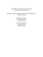
3.1—Honeycomb
Honeycomb (Fig. 1) is a condition of irregular voids due
to failure of the mortar to effectively fill the spaces between
coarse aggregate particles. Where bridging of the coarse ag-
gregate particles or stiffness of the mixture is a cause of hon-
eycomb, vibration may assist in overcoming the bridging by
increasing the flowability of the concrete. Factors that may
contribute to honeycombing are: congested reinforcement,
segregation resulting in insufficient paste content, and im-
proper fine aggregate to total aggregate ratio, improper plac-
ing techniques, rapid stiffening of hot concrete, difficult
construction conditions, and insufficient consolidation ef-
fort. Changes in construction practices and in mixture pro-
portions to improve workability and the use of water-
reducing admixtures to increase slump may assist in reduc-
ing or preventing honeycombing.
3.2—Air voids in formed surfaces
Bug holes (Fig. 2) are small regular or irregular cavities,
ranging from nearly invisible to 25 mm (1 in.) but usually not
exceeding 15 mm (9/16 in.) in diameter, that result from en-
trapment of air bubbles in the surface of formed concrete
during placement and consolidation. Bug holes on vertical
faces are more likely to occur in sticky or stiff concrete mix-
tures of low workability that may have an excessive fine ag-
gregate content or entrapped air content, or both. Also, the
use of vibrators with too high of an amplitude or the lack of
complete insertion of the vibrator head may result in an in-
creased quantity of air-voids. Air voids vary in size from mi-
croscopic to about 25 mm (1 in.). Excess water normally
manifests itself in other textural effects such as bleeding
channels or sand streaks on vertical formed surfaces. Bleed
water voids can form at the top of a column and on battered
formed surfaces. Surface voids can be minimized by the pro-
cedures discussed in Section 4.
3.3—Form streaking
Form streaking (Fig. 3) is caused by mortar leaking through
form joints and tie holes and may be aggravated by overvibra-
tion from vibrators that are too powerful, or by using
forms
that vibrate excessively during consolidation.
Fig. 1—Honeycomb.
309.2R-7CONSOLIDATION-RELATED SURFACE EFFECTS
Placing excessively wet or high-slump concrete mixtures
will result in more mortar washing out through tie holes and
loose fitting forms. Special care is sometimes required when
high-range water-reducing admixtures are used, as they tend
to increase leakage at form joints.
3.4—Aggregate transparency
Aggregate transparency (Fig. 4) is a condition character-
ized by a mottled appearance on the surface that results from
deficiencies in the mortar. It may occur when concrete mix-
tures have low fine aggregate content, dry or porous aggre-
gates, or high slump with some lightweight and normal-
weight aggregates. Also, high density or glossy form surfac-
es may cause aggregate transparency.
3.5—Subsidence cracking
Subsidence cracking (Fig. 5) results from the development
of tension when the concrete settles closed to after time of
initial setting. Cracks are caused because the upper concrete
bridges between the forms while the lower concrete settles.
These cracks may occur when there is an insufficient inter-
val between placing the concrete in the columns and placing
the concrete for the slabs or beams. They may also occur ad-
jacent to block-outs or over reinforcing bars with shallow
cover.
To prevent subsidence cracking, the concrete can be revi-
brated. Revibration is most effective when done at the latest
time at which the vibrator head will readily penetrate the
concrete under its own weight. Subsidence cracking over re-
inforcing bars can be controlled by increasing concrete cov-
er during the design phase and by using low-slump concrete
that is well-consolidated.
3.6—Color variation
Color variation (Fig. 6) may occur within a placement if
the concrete is not uniform or is incompletely mixed.
Vibrators inserted too close to the form can cause color
variation by marring the form surface. External vibration
used haphazardly may also cause color variation. Further-
more, color variations may result from nonuniform absorp-
tion, nonuniform application of the release agent, or both.
3.7—Sand streaking
Sand streaking (Fig. 7) is a streak of exposed fine aggre-
gate in the surface of the formed concrete caused by heavy
bleeding along the form.
It frequently results from the use of harsh, wet mixtures,
particularly those deficient in the 300 to 150 µm (No. 50 to
No. 100) and smaller sizes. Streaking tendencies increase
when the ratio of fine aggregate to cementitious materials in-
creases, such as in lean mixtures. Although the characteris-
tics of Portland cement and pozzolans, if used, have some
influence on bleeding, the grading of the fine aggregate is of
greater importance. Sand streaking is controlled by the use of
tight forms, proper mixture proportioning, and using well-
graded fine aggregate to minimize bleeding. Streaking can
be aggravated by excessive vibration, overmanipulation of
the vibrator, the use of a vibrator with excessive amplitude;
or excess water at the bottom of the form forced up along the
form face by hydraulic pressure.
Fig. 2—Air surface voids. Fig. 3—Form streaking.
309.2R-8 ACI COMMITTEE REPORT
3.8—Layer lines
Layer lines (Fig. 8) are dark horizontal lines on formed sur-
faces that indicate the boundary between concrete placements.
Layer lines are caused by premature stiffening or insufficient
consolidation of the previous layer of concrete due to lack of
penetration of the vibrator into that layer, or the use of a mor-
tar bonding layer between placements.
3.9—Form offsets
Form offsets (Fig. 9) are usually caused by inadequate
stiffness or anchorage of the forms and can be aggravated by
an excessive rate of placement or by using an excessively
powerful vibrator, or both.
3.10—Cold joints
Cold joints (Fig. 10) can often be avoided by contingency
planning, backup equipment, working to keep the concrete
surface alive, the use of retarding admixtures, and working
the vibrator into lower lifts.
CHAPTER 4—MINIMIZING SURFACE EFFECTS
A number of studies have been made to determine how to
achieve better consolidation resulting in fewer surface blem-
ishes (Shilstone, 1977; Stamenkovic, 1973; Samuelson,
1970; and Reading, 1972). To minimize the size and number
of bug holes and all other effects, the following practices
should be followed:
• Vibration period should be of sufficient duration;
• Vibrator insertions should be properly spaced and over-
lapped and the vibrator removed slowly;
• Each concrete layer should be consolidated from the
bottom upward;
• Vibration periods should be increased on withdrawal
when using impermeable forms that permit air trapped
at the form surface to escape through joints as between;
• Inward sloping forms and other complex design details
should be avoided;
• Depth of placement layers should be limited;
• Vibrator should penetrate into the previous layer;
• Tightening devices and gaskets to prevent leakage at
form joints should be provided as necessary; and
• Placing ports should be designed into the forms as
necessary.
Where practical, bug holes can be minimized by the use of
a 65-mm-(2-1/2 in )-diameter vibrator of high frequency
Fig. 4—Aggregate transparency.
Fig. 5—Subsidence cracking.
Fig. 6—Color variation.
309.2R-9CONSOLIDATION-RELATED SURFACE EFFECTS
with medium to low amplitude. The vibrator should be im-
mersed in the concrete around the perimeter of the form
without damaging the form. Where reinforcement is placed
near the form wall, the vibrator must be inserted inside the
reinforcement. Care should be taken to ensure that the vibra-
tor has a sufficient radius of action to liquefy the concrete at
the form.
Form vibration may be used to supplement the internal vi-
bration. However, doing so may cause a major increase in
form pressure. An alternate procedure is to use a high-fre-
quency, low-amplitude form vibrator. Vibration procedures
should be evaluated at the beginning of a project to determine
the vibration time for each type of vibrator for a given mix-
ture. Guidance on the selection of appropriate vibration am-
plitudes, frequencies, and equipment is given in ACI 309R.
In areas where surface air voids are most prevalent, revi-
bration may be used to reduce them. Revibration is more ef-
fective if it is done at the latest possible time at which the
vibrator head will readily penetrate the concrete under its
own weight. Greater benefits are obtained with higher slump
concrete mixtures, especially in the upper portion of a place-
ment where excessive entrapped air voids are most preva-
lent. However, this practice may increase laitance that must
be removed from horizontal construction joints. And may
create color non-uniformity.
Other measures, such as altering mixture proportions, us-
ing high-range water-reducing admixtures, and using small-
er nominal maximum size aggregate to improve workability
Fig. 7—Sand streaking.
Fig. 8—Layer lines.
Fig. 9—Form offsets.
Fig. 10—Cold joints.
309.2R-10
ACI COMMITTEE REPORT
should also be considered as methods of minimizing surface
effects, provided that design requirements are met. These
measures have often been successful, particularly when try-
ing to consolidate concrete in congested areas. Further guid-
ance can be obtained from ACI 309R.
CHAPTER 5—CONSOLIDATION OF PREPLACED-
AGGREGATE CONCRETE
The causes and cures of blemishes in concrete produced
by the preplaced-aggregate (PA) concrete method (ACI
304.1R, Chapter 7) are different from conventionally mixed
and placed concrete in certain aspects.
The rate of grout rise in preplaced aggregate should be
about 0.3 m/min (1 ft/min) with a maximum of 0.6 m/min
(2 ft/min). If the supply is too rapid, the grout will rise fast-
er through the large voids and cascade into the smaller
ones, trapping air. The result is spotty honeycombing. To
avoid the occurrence of layer lines, the lower ends of the
grout injection ports should always be maintained at least 0.3
to 0.6 m (1 to 2 ft) below the grout surface.
Grout will not penetrate pockets of fine aggregate; fines
that collect against side or bottom forms will produce honey-
combing. Also, care should be taken to ensure that coarse ag-
gregate fills the space between the reinforcement and forms,
and that no large voids are left that will be subsequently
filled
with grout. Large surface areas of grout not subdivided by
coarse aggregate may show crazing from drying shrinkage.
Coarse aggregate should be saturated when placed and at
the time it is grouted. If rewetting in the forms is required, a
fog spray may be applied sparingly to dampen the upper 0.3
m (1 ft) or so. If the entire mass of aggregate needs re-wet-
ting, the forms should be inundated with water from the bot-
tom, then drained off slowly. Large quantities of water
applied to the top of the aggregate will wash fines to the bot-
tom, resulting in a poor surface or honeycomb.
Light vibration of forms with external vibrators permit the
grout to cover the points of coarse aggregate in contact with
the form. Overvibration of the form should be avoided, how-
ever, as it will induce bleeding that may result in sand streak-
ing. Some trial and error may be required to determine the
optimum amount of form vibration. Form design must be in
conformance with increased pressure. Bolted connections in
formwork require lock washers or double nutting. Formwork
under external vibration requires positive attachment to foot-
ing or previous placement.
Where the appearance of formed surfaces is important, a
test section of comparable height should be produced, the
surface examined, and adjustments made to grading, placing,
and consolidation procedures adjusted to obtain an accept-
able result.
CHAPTER 6—CONCLUSION
Faulty design and construction practices can result in
blemishes in formed concrete surfaces. To keep these effects
within tolerable limits, an awareness of their causes and their
cures is essential. The causes of these effects may lie in
initial design concepts, specification, materials selection,
proportioning, placement, consolidation, or workmanship.
Frequently, the services of a specialist in concrete and con-
crete construction can be used to assist in obtaining concrete
surfaces conforming to the higher standards. The execution
of the work by well-trained work crews under competent su-
pervision will ensure a concrete surface meeting the require-
ments of the owner or designer.
CHAPTER 7—SURFACE CONDITION OUTLINE
The following is an outline of items that should be consid-
ered by designers and constructors when reporting on the
condition of a concrete surface and the possible causes of ef-
fects. By following this checklist and referring to earlier
chapters in this document, the designer or constructor should
then be in a position to identify the cause and correct most
types of surface effects.
1—Description of structure
1.1—Name, location, type, and size
1.2—Owner, project engineer, contractor
1.3—Design
1.3.1—Architect and/or engineer
1.4—Photographs
1.4.1—General view
2—
Description of wall, beam, or column showing blemishes
2.1—Location, size
2.2—Type of concrete
2.2.1—Architectural
2.2.2—Structural
3—Effect
3.1—Name
3.1.1—Description
3.1.2—Photographs
4—Causes
4.1—Design of member
4.1.1—Reinforcement (spacing and size)
4.1.2—Width, depth
4.1.3—Configuration
4.2—Forms
4.2.1—Method
4.2.2—Shape
4.2.3—Anchorage
4.2.4—Insulation
4.2.5—Material type, new or used
4.2.6—Form coatings
4.2.7—Texture and finish
4.2.8—Tightness
4.2.9—Structural adequacy
4.3—Construction conditions
4.3.1—Temperature
4.3.2—Wind
4.3.3—Humidity
4.3.4—Precipitation
4.3.5—Placing accessibility
4.3.6—Precautions, covered in 4.5
4.4—Properties of fresh concrete
4.4.1—Proportions
4.4.2—Workability
309.2R-11CONSOLIDATION-RELATED SURFACE EFFECTS
4.4.3—Grading of aggregate
4.4.4—Slump
4.4.5—Nominal maximum size aggregate
4.4.6—Cohesiveness
4.4.7—Air content
4.4.8—Time of setting
4.5—Placement
4.5.1—Rate
4.5.2—Conditions
4.5.3—Adequacy of equipment
4.6—Consolidation
4.6.1—Frequency
4.6.2—Amplitude
4.6.3—Physical size
4.6.4—Schedule of insertions
4.6.5—Number of vibrators
4.6.6—Depth of penetration
4.6.7—Length of vibration
CHAPTER 8—REFERENCES
8.1—Recommended references
The documents of the various standards-producing orga-
nizations referred to in this report are listed below with their
serial designation.
American Concrete Institute
ACI 116R Cement and Concrete Terminology
ACI 303R Guide to Cast-In-Place Architectural Con-
crete Practice
ACI 304.1R Guide for the Use of Prepackaged-Aggre-
gate Concrete for Structural and Mass
Concrete Applications
ACI 309R Guide for Consolidation of Concrete
ACI 309.1R Behavior of Fresh Concrete During Vi-
bration
ACI 347R Guide to Formwork for Concrete
American Society for Testing and Materials
ASTM C 33 Specification for Concrete Aggregates
The above publications may be obtained from:
American Concrete Institute
P.O. Box 9094
Farmington Hills, MI 48333-9094
American Society for Testing and Materials
100 Barr Harbor Drive
West Conshohocken, PA 19428-2959
8.2—Cited references
Backstrom, J. E.; Burrows, R. W.; Mielenz, R. C.; and Wolkodorff, V.
E., 1958, “Origin, Evolution and Effects of the Air Void System in Con-
crete, Part 3—Influence of Water-Cement Ratio and Compaction,” ACI
J
OURNAL
, Proceedings V. 55, Sept., pp. 359-375.
International Council for Building Research, 1975, “Tolerances on
Blemishes of Concrete,” CIB Report No. 24, International Council for
Building Research Studies and Documentation, Rotterdam, 8 pp.
Mather, B., 1987, “The Warmer the Concrete the Faster the Cement
Hardens,” Concrete International, V. 9, No. 8, Aug., pp. 29-33.
Reading, T. J., 1972, “The Bug Hole Problem,” ACI J
OURNAL
, Proceed-
ings V. 69, No. 3, Mar., pp. 165-177.
Samuelson, P., 1970, “Voids in Concrete Surfaces,” ACI J
OURNAL
, Pro-
ceedings V. 67, No. 22, Nov., pp. 868-874.
Shilstone, J. M., 1977, “Surface Blemishes in Formed Concrete,” Pro-
ceedings, RILEM/ASTM/CIB Symposium on Performance Evaluation of
External Vertical Surfaces of Buildings (Otaniemi, Espoo, Aug Sept.),
Technical Research Centre of Finland, Espoo, Finland, pp. 3-7.
Stamenkovic, H., 1973, “Surface Voids Can Be Controlled,” Concrete
Construction, V. 18, No. 12, Dec., pp. 597-598, 600.
8.3—Bibliography
Fiorato, A. E., 1973, Geometric Imperfections in Concrete Structures (A
Literature Survey), National Swedish Institute for Building Research,
Stockholm, Sweden.
Harding, M. A., 1995, “Vibrating Concrete in Wall Forms,” Concrete
Construction, V. 40, No. 2, Feb., pp. 180-184.
Harrell, T. R., and Goswick, G. M., 1987, “Tunnel Concrete—Consoli-
dation Achieved by a Harmonic Blend of Internal and External Vibration,”
Consolidation of Concrete, SP-96, American Concrete Institute, Farming-
ton Hills, Mich., pp. 102-118.
Holland, T. C.; Husbands, T. B.; Buck, A. D.; and Wong, G. S., 1980,
Concrete Deterioration in Spillway Warm-Water Chute, Raystown Dam.
Pennsylvania (Final Report), U. S. Army Engineer Waterways Experiment
Station, Vicksburg, Miss., Structures Lab. WES/MP/SL-80-19; CTIAC-42,
55 pp.
Houston, B. J., 1967, Methods of Reducing the Size and Number of Voids
on Formed Concrete Surfaces, Report No. TR 6-788, U. S. Army Engineer
Waterways Experiment Station, Vicksburg, Miss., 36 pp.
Hurd, M. K., 1993, “Patterned Form Liners for Architectural Concrete,”
Concrete Construction, V. 38, No. 5, May 5, 5 pp.
Kennedy, T. B., 1960, Investigation of Methods of Finishing Formed
Concrete Surfaces, Report No. TR 6-559, U.S. Army Engineer Waterways
Experimental Station, Vicksburg, Miss., 19 pp.
Kenney, A. R., 1984, “Problems and Surface Blemishes in Architectural
Cast-in-Place Concrete,”
Concrete International
, V. 6, No. 1, Jan., pp. 50-55.
Kenney, A. R., and Kenney, B. P., 1986, “Problems and Repairs in Tilt-
Up Construction,” Concrete International, V. 8, No. 6, Jun., pp. 41-50.
King, J. C., 1971, “Special Concretes and Mortars,” Handbook of Heavy
Construction, 2nd Edition, McGraw-Hill Book Co., New York, pp. 22-1 to
22-17.
Mass, G. R., 1987, “Consolidation of Concrete,” Lewis H. Tuthill Inter-
national Symposium on Concrete and Concrete Construction, SP-104,
Gant T. Halvorsen, ed., American Concrete Institute, Farmington Hills,
Mich., pp. 185-204.
Reading, T. J., 1985, “Deleterious Affects of Wood Forms on Concrete
Surfaces, Concrete International, V. 7, No. 11, Nov., pp. 57-62.
Sansalone, M., and Carino, N. J., 1988, “Impact-Echo Method: Detecting
Honeycombing, Depth of Surface-Opening Cracks, and Ungrouted Ducts
(Final Report),” Concrete International, V. 10, No. 4, Apr., pp. 38-46.
Shilstone, J. M., 1979, “Surface Blemishes in Formed Concrete,” Con-
crete Construction, V. 24, No. 11, Nov., pp. 719 and 765.
Smith, John R., 1984, “Architectural Concrete: Defects Demand Discre-
tion,” Concrete International, V. 6 No. 1, Jan., pp. 64-66.
Watanaba, T., and Uomoto, T., 1993, “Monitoring Concrete Placing by
Infrared Image Analysis,”
Doboku Gakkai Rombun-Hokokushu/Proceed-
ings of the Japan Society of Civil Engineers
, No. 478, Part 50-21, pp. 55-59.