service life prediction state of the art report
Bạn đang xem bản rút gọn của tài liệu. Xem và tải ngay bản đầy đủ của tài liệu tại đây (631.44 KB, 44 trang )
ACI 365.1R-00 became effective January 10, 2000.
Copyright 2000, American Concrete Institute.
All rights reserved including rights of reproduction and use in any form or by any
means, including the making of copies by any photo process, or by electronic or
mechanical device, printed, written, or oral, or recording for sound or visual reproduc-
tion or for use in any knowledge or retrieval system or device, unless permission in
writing is obtained from the copyright proprietors.
ACI Committee Reports, Guides, Standard Practices, and
Commentaries are intended for guidance in planning, de-
signing, executing, and inspecting construction. This docu-
ment is intended for the use of individuals who are
competent to evaluate the significance and limitations
of its content and recommendations and who will accept
responsibility for the application of the material it con-
tains. The American Concrete Institute disclaims any and
all responsibility for the stated principles. The Institute shall
not be liable for any loss or damage arising therefrom.
Reference to this document shall not be made in contract
documents. If items found in this document are desired by
the Architect/Engineer to be a part of the contract docu-
ments, they shall be restated in mandatory language for in-
corporation by the Architect/Engineer.
365.1R-1
Service-Life Prediction—State-of-the-Art Report
ACI 365.1R-00
This report presents current information on the service-life prediction of
new and existing concrete structures. This information is important to both
the owner and the design professional. Important factors controlling the
service life of concrete and methodologies for evaluating the condition of
the existing concrete structures, including definitions of key physical prop-
erties, are also presented. Techniques for predicting the service life of con-
crete and the relationship between economics and the service life of
structures are discussed. The examples provided discuss which service-life
techniques are applied to concrete structures or structural components.
Finally, needed developments are identified.
Keywords:
construction; corrosion; design; durability; rehabilitation;
repair; service life.
CONTENTS
Chapter 1—Introduction, p. 365.1R-2
1.1—Background
1.2—Scope
1.3—Document use
Chapter 2—Environment, design, and construction
considerations, p. 365.1R-3
2.1—Introduction
2.2—Environmental considerations
2.3—Design and structural loading considerations
2.4—Interaction of structural load and environmental effects
2.5—Construction-related considerations
Chapter 3—In-service inspection, condition
assessment, and remaining service life, p. 365.1R-11
3.1—Introduction
3.2—Evaluation of reinforced concrete aging or degrada-
tion effects
3.3—Condition, structural, and service-life assessments
3.4—Inspection and maintenance
Chapter 4—Methods for predicting the service life
of concrete, p. 365.1R-17
4.1—Introduction
4.2—Approaches for predicting service life of new concrete
4.3—Prediction of remaining service life
4.4—Predictions based on extrapolations
4.5—Summary
Chapter 5—Economic considerations, p. 365.1R-24
5.1—Introduction
5.2—Economic analysis methods
5.3—Economic issues involving service life of concrete
structures
Reported by ACI Committee 365
S. L. Amey
*
M. Geiker D. G. Manning
J. P. Archibald
C. J. Hookham P. K. Mukherjee
N. R. Buenfeld W. J. Irwin J. Pommersheim
P. D. Cady
*
A. Kehnemui M. D. Thomas
C. W. Dolan
R. E. Weyers
*
*
Report chapter coordinators
†
Deceased
‡
Report coordinator
James R. Clifton
*†
Chairman
Dan J. Naus
*‡
Secretary
365.1R-2 ACI COMMITTEE REPORT
Chapter 6—Examples of service-life techniques,
p. 365.1R-27
6.1—Example I—Relationship of amount of steel corro-
sion to time of concrete spalling
6.2—Example II—Comparison of competing degradation
mechanisms to calculate remaining life
6.3—Example III—Utilization of multiple input to calcu-
late the life of a structure
6.4—Example IV—When to repair, when to rehabilitate
6.5—Example V—Utilization of reaction rate to calculate
the life of a sewer pipe
6.6—Example VI—Estimating service life and mainte-
nance demands of a diaphragm wall exposed to sa-
line groundwater
6.7—Example VII—Application of time-dependent reli-
ability concepts to a concrete slab and low-rise shear
wall
Chapter 7—Ongoing work and needed
developments, p. 365.1R-36
7.1—Introduction
7.2—Designing for durability
Chapter 8—References, p. 365.1R-37
8.1—Referenced standards and reports
8.2—Cited references
CHAPTER 1—INTRODUCTION
1.1—Background
Service-life concepts for buildings and structures date
back to when early builders found that certain materials and
designs lasted longer than others (Davey 1961). Throughout
history, service-life predictions of structures, equipment, and
other components were generally qualitative and empirical.
The understanding of the mechanisms and kinetics of many
degradation processes of concrete has formed a basis for
making quantitative predictions of the service life of struc-
tures and components made of concrete. In addition to actual
or potential structural collapse, many other factors can gov-
ern the service life of a concrete structure. For example, ex-
cessive operating costs can lead to a structure’s replacement.
This document reports on these service-life factors, for both
new and existing concrete structures and components.
The terms “durability” and “service life” are often errone-
ously interchanged. The distinction between the two terms is
evident when their definitions, as given in ASTM E 632, are
compared:
Durability is the capability of maintaining the serviceabil-
ity of a product, component, assembly, or construction over
a specified time. Serviceability is viewed as the capacity of
the above to perform the function(s) for which they are de-
signed and constructed.
Service life (of building component or material) is the pe-
riod of time after installation (or in the case of concrete,
placement) during which all the properties exceed the mini-
mum acceptable values when routinely maintained. Three
types of service life have been defined (Sommerville 1986).
Technical service life is the time in service until a defined un-
acceptable state is reached, such as spalling of concrete, safety
level below acceptable, or failure of elements. Functional ser-
vice life is the time in service until the structure no longer ful-
fills the functional requirements or becomes obsolete due to
change in functional requirements, such as the needs for in-
creased clearance, higher axle and wheel loads, or road wid-
ening. Economic service life is the time in service until
replacement of the structure (or part of it) is economically
more advantageous than keeping it in service.
Service-life methodologies have application both in the
design stage of a structure—where certain parameters are
established, such as selection of water-cementitious materi-
als ratios (w/cm), concrete cover, and admixtures—and in
the operation phase where inspection and maintenance
strategies can be developed in support of life-cycle cost
analyses. Service-life design includes the architectural and
structural design, selection and design of materials, mainte-
nance plans, and quality assurance and quality control plans
for a future structure (CEB/RILEM 1986). Based on mixture
proportioning, including selection of concrete constituents,
known material properties, expected service environment,
structural detailing (such as concrete cover), construction
methods, projected loading history, and the definition of end-
of-life, the service life can be predicted and concrete with a rea-
sonable assurance of meeting the design service life can be
specified (Jubb 1992, Clifton and Knab 1989). The acceptance
of advanced materials, such as high-performance concrete, can
depend on life-cycle cost analyses that consider predictions of
their increased service life.
Methodologies are being developed that predict the service
life of existing concrete structures. To predict the service life
of existing concrete structures, information is required on the
present condition of concrete, rates of degradation, past and
future loading, and definition of the end-of-life (Clifton
1991). Based on remaining life predictions, economic deci-
sions can be made on whether or not a structure should be
repaired, rehabilitated, or replaced.
Repair and rehabilitation are often used interchangeably.
The first step of each of these processes should be to address
the cause of degradation. The distinction between rehabilita-
tion and repair is that rehabilitation includes the process of
modifying a structure to a desired useful condition, whereas
repair does not change the structural function.
To predict the service life of concrete structures or ele-
ments, end-of-life should be defined. For example, end-of-
life can be defined as:
• Structural safety is unacceptable due to material degra-
dation or exceeding the design load-carrying capacity;
• Severe material degradation, such as corrosion of steel
reinforcement initiated when diffusing chloride ions
attain the threshold corrosion concentration at the
reinforcement depth;
• Maintenance requirements exceed available resource
limits;
• Aesthetics become unacceptable; or
• Functional capacity of the structure is no longer suffi-
cient for a demand, such as a football stadium with a
deficient seating capacity.
365.1R-3
SERVICE-LIFE PREDICTION—STATE-OF-THE-ART REPORT
Essentially all decisions concerning the definition of end-
of-life are combined with human safety and economic con-
siderations. In most cases, the condition, appearance, or ca-
pacity of a structure can be upgraded to an acceptable level;
however, costs associated with the upgrade can be prohibi-
tive. Guidance on making such decisions is included in this
report.
1.2—Scope
This report begins with an overview of important factors
controlling the service life of concrete, including past and
current design of structures; concrete materials issues; field
practices involved with placing, consolidating, and curing of
concrete; and in-service stresses induced by degradation
processes and mechanical loads. Methodologies used to
evaluate the structural condition of concrete structures and
the condition and properties of in-service concrete materials
are presented. Methods are reviewed for predicting the ser-
vice life of concrete, including comparative methods, use of
accelerated aging (degradation) tests, application of mathe-
matical modeling and simulation, and application of reliabil-
ity and stochastic concepts. This is followed by a discussion
of relationships between economics and the life of struc-
tures, such as when it is more economical to replace a struc-
ture than to repair or rehabilitate. Examples are described in
which service-life techniques are applicable to concrete
structures or structural components. Finally, needed devel-
opments to improve the reliability of service-life predictions
are presented.
1.3—Document use
This document can assist in applying available methods
and tools to predict service life of existing structures and
provide actions that can be taken at the design or construc-
tion stage to increase service life of new structures.
CHAPTER 2—ENVIRONMENT, DESIGN, AND
CONSTRUCTION CONSIDERATIONS
2.1—Introduction
Reinforced concrete structures have been and continue to
be designed in accordance with national or international con-
sensus codes and standards such as ACI 318, Eurocode 2, and
Comité Euro International du Béton (1993). The codes are de-
veloped and based on knowledge acquired in research and
testing laboratories, and supplemented by field experience.
Although present design procedures for concrete are domi-
nated by analytical determinations based on strength princi-
ples, designs are increasingly being refined to address
durability requirements (for example, resistance to chloride
ingress and improved freezing-and-thawing resistance). In-
herent with design calculations and construction documents
developed in conformance with these codes is a certain level
of durability, such as requirements for concrete cover to pro-
tect embedded steel reinforcement under aggressive environ-
mental conditions. Although the vast majority of reinforced
concrete structures have met and continue to meet their func-
tional and performance requirements, numerous examples
can be cited where structures, such as pavements and bridges,
have not exhibited the desired durability or service life. In ad-
dition to material selection and proportioning to meet con-
crete strength requirements, a conscious effort needs to be
made to design and detail pavements and bridges for long-
term durability (Sommerville 1986). A more holistic ap-
proach is necessary for designing concrete structures based
on service-life considerations. This chapter addresses envi-
ronmental and structural loading considerations, as well as
their interaction, and design and construction influences on
the service life of structures.
2.2—Environmental considerations
Design of reinforced concrete structures to ensure adequate
durability is a complicated process. Service life depends on
structural design and detailing, mixture proportioning, concrete
production and placement, construction methods, and mainte-
nance. Also, changes in use, loading, and environment are im-
portant. Because water or some other fluid is involved in
almost every form of concrete degradation, concrete perme-
ability is important.
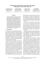
The process of chemical and physical deterioration of con-
crete with time or reduction in durability is generally depen-
dent on the presence and transport of deleterious substances
through concrete,
*
and the magnitude, frequency, and effect of
applied loads. Figure 2.1 (CEB 1992) presents the relationship
between the concepts of concrete durability and performance.
The figure shows that the combined transportation of heat,
moisture, and chemicals, both within the concrete and in ex-
change with the surrounding environment, and the parameters
controlling the transport mechanisms constitute the principal
elements of durability. The rate, extent, and effect of fluid
transport are largely dependent on the concrete pore structure
(size and distribution), presence of cracks, and microclimate at
the concrete surface. The primary mode of transport in un-
cracked concrete is through the bulk cement paste pore struc-
ture and the transition zone (interfacial region between the
particles of coarse aggregate and hydrated cement paste). The
physical-chemical phenomena associated with fluid move-
ment through porous solids is controlled by the solid’s perme-
ability (penetrability). Although the coefficient of
permeability of concrete depends primarily on the w/cm and
maximum aggregate size, it is also influenced by age, consol-
idation, curing temperature, drying, and the addition of chem-
ical or mineral admixtures. Concrete is generally more
permeable than cement paste due to the presence of microc-
racks in the transition zone between the cement paste and ag-
gregate (Mehta 1986). Table 2.1 presents chloride diffusion
and permeability results obtained from the 19 mm maximum
size crushed limestone aggregate mixtures presented in Table
2.2.
†
Additional information on the types of transport process-
es important with respect to the various aspects of concrete du-
rability, such as simple diffusion, diffusion plus reaction,
imbibition (capillary suction), and permeation, is available
*
Absorption is the process by which a liquid is drawn into and tends to fill perme-
able pores in a porous solid body; also the increase in mass of a porous solid body
resulting from the penetration of a liquid into its permeable pores. Permeability is
defined as the ease with which a fluid can flow through a solid. Diffusion is the move-
ment of one medium through another.
†
The results presented are for this testing method, and would be somewhat different
if another testing method had been used.
365.1R-4 ACI COMMITTEE REPORT
elsewhere (Lawrence 1991, Pommersheim and Clifton 1990,
Kropp and Hilsdorf 1995).
Two additional factors are considered with respect to fab-
rication of durable concrete structures: the environmental-
exposure condition and specific design recommendations
pertaining to the expected form of aggressive chemical or
physical attack (for example, designing the structure to pre-
vent accumulation of water). Exposure conditions or severity
are generally handled through a specification that addresses
the concrete mixture (for example strength, w/cm, and ce-
ment content), and details (such as concrete cover), as dictat-
ed by the anticipated exposure. Summarized in the following
paragraphs are descriptions of the primary chemical and
physical degradation processes that can adversely impact the
durability of reinforced concrete structures and guidelines
for minimizing or eliminating potential consequences of
Table 2.1—Chloride transport and permeability results for selected concretes*
Mixture
no.
†
Cure time,
days
Rapid test for permeability
to Cl
–
, 3% NaCl solution,
total charge, Coulombs
90-day ponding,
% Cl
–
by weight
of concrete
‡
Permeability,
µ
Darcys
§
Porosity, % by
volumeHydraulic Air
1
1 44 0.013
—
||
37 8.3
7 65 0.013
—
||
29 7.5
2
1 942 0.017
—
||
28 9.1
7 852 0.022
—
||
33 8.8
3
1 3897 0.062 0.030 130 11.3
7 3242 0.058 0.027 120 11.3
4
1 5703 0.103 0.560 120 12.4
7 4315 0.076 0.200 170 12.5
5
1 5911 0.104 0.740 200 13.0
7 4526 0.077 0.230 150 12.7
6
1 7065 0.112 4.100 270 13.0
7 5915 0.085 0.860 150 13.0
*
Whiting, 1988.
†
Refer to Table 2.2 for description of mixtures.
‡
Average of three samples taken at depths from 2 to 40 mm.
§
To convert from
µ
Darcys to m
2
, multiply by 9.87
×
10
–7
.
||
Permeability too small to measure.
Fig. 2.1—Relationships between the concepts of concrete durability and performance
(CEB 1992).
365.1R-5
SERVICE-LIFE PREDICTION—STATE-OF-THE-ART REPORT
these degradation mechanisms. Combined effects where
more than one of these processes can be simultaneously oc-
curring are also briefly addressed. Available methods and
strategies for prediction of the service life of a new or exist-
ing reinforced concrete structure with respect to these mech-
anisms are described in Chapter 4.
2.2.1 Chemical attack—Chemical attack involves the al-
teration of concrete through chemical reaction with either
the cement paste, coarse aggregate, or embedded steel re-
inforcement. Generally, the attack occurs on the exposed
surface region of the concrete (cover concrete), but with
the presence of cracks or prolonged exposure, chemical at-
tack can affect entire structural cross sections. Chemical
causes of deterioration can be grouped into three catego-
ries (Mehta 1986):
1. Hydrolysis of cement paste components by soft water;
2. Cation-exchange reactions between aggressive fluids
and cement paste; and
3. Reactions leading to formation of expansion product.
Results from prolonged chemical attack range from cos-
metic damage to loss of structural section and monolithic be-
havior. Chemical attack of embedded steel reinforcement
can also occur.
2.2.1.1 Leaching—Pure water that contains little or no
calcium ions, or acidic ground water present in the form of
dissolved carbon dioxide gas, carbonic acid, or bicarbonate
ion, tend to hydrolyze or dissolve the alkali oxides and calci-
um-containing products resulting in increasing permeability.
The rate of leaching is dependent on the amount of dissolved
salts contained in the percolating fluid, rate of permeation of
the fluid through the cement paste matrix, and temperature.
The rate of leaching can be lowered by minimizing the per-
meation of water through the concrete (interconnected capil-
lary cavities) by using low-permeability concretes and
barriers. Factors related to the production of low-permeability
concretes include low w/cm, adequate cement content, poz-
zolanic additions, and proper compaction and curing condi-
tions. Polymeric modification can also be used to provide
low permeability concretes. Similarly, attention should be
given to aggregate size and gradation, thermal and drying
shrinkage strains, avoiding loads that produce cracks, and
designing and detailing to minimize exposure to moisture.
Requirements in codes and suggested guidelines for w/cm
are generally based on strength or exposure conditions (ACI
318, ACI 201.1R, ACI 301, ACI 350R, ACI 357R). ACI
224R provides crack-control guidelines and ACI 515.1R
provides information on barrier systems for concrete.
2.2.1.2 Delayed ettringite formation—Structures under-
going delayed ettringite formation (DEF) can exhibit expan-
sion and cracking. The distress often is attributed to
excessive steam curing that prevents the formation or causes
decomposition of ettringite that is normally formed during
the early hydration of portland cement. Use of cements with
high sulfate contents in which the sulfate has very low solu-
bility can also lead to DEF. In one case where this has been
reported (Mielenz et al. 1995), it was thought that the occur-
rence of DEF was due to the sulfate formed in the clinker of
the cement being present as anhydrite and as a component of
the silicate phases which are slowly soluble. Ettringite is the
product of the reaction between sulfate ions, calcium alumi-
nates, and water. If structures susceptible to DEF are later ex-
posed to water, ettringite can reform in the paste as a massive
development of needle-like crystals, causing expansive forc-
es that result in cracking. The extent of development of DEF
is dependent on the amount of sulfate available for late
ettringite development in the particular concrete and on the
presence of water during the service life. Elevated tempera-
tures also increase the potential for damage due to DEF. Pre-
vention or minimization of DEF can be accomplished by
lowering the curing temperature, limiting clinker sulfate lev-
els, avoiding excessive curing for potentially critical sulfate
to aluminate ratios, preventing exposure to substantial water
in service, and using proper air entrainment. Neither the
mechanisms involved in DEF nor their potential conse-
quences relative to concrete durability are completely under-
stood. DEF leads to a degradation in concrete mechanical
properties, such as compressive strength, and can promote
increased permeability. A detailed review of over 300 publi-
cations dealing with DEF is available (Day 1992).
2.2.1.3 Sulfate attack—Sulfates present in the aggre-
gates, soils, ground water, and seawater react with the calci-
um hydroxide [Ca(OH)
2
] and the hydrated tricalcium
aluminate (C
3
A) to form gypsum and ettringite, respectively.
These reactions can result in deleterious expansion and pro-
duce concretes with reduced strength because of decomposi-
tion and expansion of the hydrated calcium aluminates.
Table 2.2—Concrete mixture proportions and characteristics*
Mixture
no.
Quantities, kg/m
3
Admixture(s)
†
w/cm Slump, cm
Air
content, %Cement
Fine
aggregate
Coarse
aggregate Water
1 446 752 1032 132 A + B
0.258
‡
119 1.6
2 446 790 1083 128 C 0.288 89 2.0
3 381 784 1075 153 D 0.401 89 2.3
4 327 794 1088 164 — 0.502 94 2.1
5 297 791 1086 178 — 0.600 107 1.8
6 245 810 1107 185 — 0.753 124 1.3
*
Whiting, 1988.
†
A = Microsilica fume at 59.4 kg/m
3
; B = Type F high-range water reducer at 25 ml/kg; C = Type F high-range water reducer at
13 ml/kg; and D = Type A water reducer at 2 ml/kg.
‡
For Mixture 1 expressed as ratio of water to total cementitious material content.
365.1R-6 ACI COMMITTEE REPORT
Increased resistance of structures to sulfate attack is provided
by fabricating them using concrete that is dense, has low per-
meability, and incorporates sulfate-resistant cement. Because
it is the C
3
A that is attacked by sulfates, the concrete vulnera-
bility can be reduced by using cements low in C
3
A, such as
ASTM C 150 Types II and V sulfate-resisting cements. Under
extreme conditions, supersulfated slag cements such as ASTM
C 595 Types VP or VS can be used. Also, improved sulfate re-
sistance can be attained by using admixtures, such as poz-
zolans and blast-furnace slag. Requirements and guidelines for
the use of sulfate-resistant concretes are based on exposure se-
verity and are provided in ACI 318 and ACI 201.2R. The re-
quirements are provided in terms of cement type, cement
content, maximum w/cm, and minimum compressive strength,
depending upon the potential for distress.
2.2.1.4 Acid and base attack—Acids can combine with
the calcium compounds in the hydrated cement paste to form
soluble materials that are readily leached from the concrete
to increase porosity and permeability. The main factors de-
termining the extent of attack are type of acid, and its concen-
tration and pH. Protective barriers are recommended to
provide resistance against acid attack.
As hydrated cement paste is an alkaline material, concrete
made with chemically stable aggregates is resistant to bases.
Sodium and potassium hydroxides in high concentrations
(>20%), however, can cause concrete to disintegrate. ACI
515.1R provides a list of the effects of chemicals on concrete.
Under mild chemical attack, a concrete with low w/cm (low
permeability) can have suitable resistance. Because corro-
sive chemicals can attack concrete only in the presence of
water, designs to minimize attack by bases might also incor-
porate protective barrier systems. Guidelines on the use of
barrier systems are also provided in ACI 515.1R.
2.2.1.5 Alkali-aggregate reactions—Expansion and
cracking leading to loss of strength, stiffness, and durability
of concrete can result from chemical reactions involving al-
kali ions from portland cement, calcium and hydroxyl ions,
and certain siliceous constituents in aggregates. Expansive
reactions can also occur as a result of interaction of alkali
ions and carbonate constituents. Three requirements are
necessary for disintegration due to alkali-aggregate reac-
tions: 1) presence of sufficient alkali; 2) availability of
moisture; and 3) the presence of reactive silica, silicate, or
carbonate aggregates. Controlling alkali-aggregate reac-
tions at the design stage is done by avoiding deleteriously
reactive aggregate materials by using preliminary petro-
graphic examinations and by using materials with proven
service histories. ASTM C 586 provides a method for assess-
ing potential alkali reactivity of carbonate aggregates. ACI
201.2R presents a list of known deleteriously reactive aggre-
gate materials. Additional procedures for mitigating alkali-
silica reactions include pozzolans, using low-alkali cements
(that is, restricting the cement alkali contents to less than
0.6% by weight sodium oxide [Na
2
O] equivalent), adding
lithium salts, and applying barriers to restrict or eliminate
moisture. The latter procedure is generally the first step in
addressing affected structures. The alkali-carbonate reaction
can be controlled by keeping the alkali content of the cement
low, by adding lithium salts, or by diluting the reactive ag-
gregate with less-susceptible material.
2.2.1.6 Steel reinforcement corrosion—Corrosion of
conventional steel reinforcement in concrete is an electro-
chemical process that forms either local pitting or general sur-
face corrosion. Both water and oxygen must be present for
corrosion to occur. In concrete, reinforcing steel with ade-
quate cover should not be susceptible to corrosion because
the highly alkaline conditions present within the concrete
(pH>12) cause a passive iron-oxide film to form on the steel
surface. Carbonation and the presence of chloride ions, how-
ever, can destroy the protective film. Corrosion of steel rein-
forcement also can be accelerated by the presence of stray
electrical currents.
Penetrating carbon dioxide (CO
2
) from the environment
reduces the pH of concrete as calcium and alkali hydroxides
are converted into carbonates. The penetration of CO
2
gen-
erally is a slow process, dependent on the concrete perme-
ability, the concrete moisture content, the CO
2
content, and
ambient relative humidity (RH). Carbonation can be acceler-
ated by the presence of cracks or porosity of the concrete.
Concretes that have low permeability and have been proper-
ly cured provide the greatest resistance to carbonation. Also,
concrete cover over the embedded steel reinforcement can be
increased to delay the onset of corrosion resulting from the
effects of carbonation.
The presence of chloride ions is probably the major cause
of corrosion of embedded steel reinforcement. Chloride ions
are common in nature and small amounts can be unintention-
ally contained in the concrete mixture ingredients. Potential
external sources of chlorides include those from accelerating
admixtures (for example, calcium chloride), application of
deicing salts, or exposure to seawater or spray. Maximum
permissible chloride-ion contents, as well as minimum con-
crete cover requirements, are provided in codes and guides
(CEB 1993, ACI 318, ACI 222R, and ACI 201.2R). Two
methods are most commonly used for determination of chlo-
ride contents in concrete: acid soluble test (total chlorides),
and water-soluble test. The chloride ion limits are presented
in terms of type of member (prestressed or conventionally re-
inforced) and exposure condition (dry or moist). Because wa-
ter, oxygen, and chloride ions are important factors in the
corrosion of embedded steel reinforcement, concrete perme-
ability is the key to controlling the process. Concrete mixtures
should be designed to ensure low permeability by using low
w/cm, adequate cementitous materials content, proper aggre-
gate size and gradation, and mineral admixtures. Methods of
excluding external sources of chloride ions from existing con-
crete, detailed in ACI 222R, include using waterproof mem-
branes, polymer impregnation, and overlay materials. ACI
222R also notes that enhanced corrosion resistance can be
provided by corrosion-resistant steels, such as stainless steel
or stainless steel cladding; application of sacrificial or non-
sacrificial coatings, such as fusion-bonded epoxy powder; use
of chemical admixtures, such as corrosion inhibitors during
the construction stage; and cathodic protection, either during
the construction stage or later in life. Additional information
on barriers that can be used to enhance corrosion resistance is
365.1R-7
SERVICE-LIFE PREDICTION—STATE-OF-THE-ART REPORT
provided in ACI 515.1R. The resistance of structures can also
be increased by designing and detailing them to promote the
runoff of moisture. Maintenance efforts to minimize a struc-
ture’s exposure to chlorides and other aggressive chemicals
should also be instituted.
2.2.1.7 Prestressing steel corrosion—High-strength
steel, such as that used in pre- or post-tensioning systems,
corrodes in the same manner as mild steel. In addition, it can
degrade due to corrosion fatigue, stress corrosion cracking,
and hydrogen embrittlement. Microorganisms can also cause
corrosion by creating local environments conducive to the
corrosion process through the intake of available food prod-
ucts and production of highly acidic waste products in the
environment around the reinforcement. Although corrosion
of prestressing steel can be either highly localized or uni-
form, most prestressing corrosion-related failures have been
the result of localized attack resulting in pitting, stress cor-
rosion, hydrogen embrittlement, or a combination of these.
Pitting is an electrochemical process that results in local pen-
etrations into the steel to reduce the cross section so that it is
incapable of supporting its load. Stress-corrosion cracking
results in the brittle fracture of a normally ductile metal or al-
loy under stress (tension or residual) in specific corrosive en-
vironments. Hydrogen embrittlement, frequently associated
with exposure to hydrogen sulfide, occurs when hydrogen
atoms enter the metal lattice and significantly reduce its duc-
tility. Hydrogen embrittlement can also occur as a result of
improper application of cathodic protection to the post-ten-
sioning system. Due to the magnitude of the load in the post-
tensioning systems, the tolerance for corrosion attack is less
than for mild steel reinforcement. Corrosion protection is
provided at installation by either encapsulating the post-ten-
sioning steel with microcrystalline waxes compounded with
organic corrosion inhibitors within plastic sheaths or metal
conduits (unbounded tendons), or by portland cement
(grouted tendons). Degradation of prestressing steel is criti-
cal because of its potential effects on monolithic behavior,
tensile capacity, and ductility.
2.2.2 Physical attack—Physical attack generally involves
the degradation of concrete due to environmental influences.
It primarily manifests itself in two forms: surface wear and
cracking (Mehta and Gerwick 1982).
Concrete damage due
to overload is not considered in this document but can lead
to loss of durability because the resulting cracks can provide
direct pathways for entry of deleterious chemicals (for ex-
ample, exposure of steel reinforcement to chlorides).
2.2.2.1 Salt crystallization—Salts can produce cracks in
concrete through development of crystal growth pressures
that arise from causes, such as repeated crystallization due to
evaporation of salt-laden water in the pores. Structures in
contact with fluctuating water levels or in contact with
ground water containing large quantities of dissolved salts
(calcium sulfate [CaSO
4
], sodium chloride [NaCl], sodium
sulfate [Na
2
SO
4
]) are susceptible to this type of degradation,
in addition to possible chemical attack, either directly or by
reaction with cement or aggregate constituents. One ap-
proach to the problem of salt crystallization is to apply seal-
ers or barriers to either prevent water ingress or subsequent
evaporation; however, if the sealer is not properly selected
and applied, it can cause the moisture content in the concrete
to increase, and not prevent the occurrence of crystallization.
2.2.2.2 Freezing-and-thawing attack—Concrete, when
in a saturated or near-saturated condition, is susceptible to
damage during freezing-and-thawing cycles produced by
the natural environment or industrial processes. One hy-
pothesis is that the damage is caused by hydraulic pressure
generated in the capillary cavities of the cement paste in a crit-
ically saturated condition as the water freezes. Factors control-
ling the resistance of concrete to freezing-and-thawing action
include air entrainment (size and spacing of air voids), perme-
ability, strength, and degree of saturation. Selection of durable
aggregate materials is also important. Guidelines for produc-
tion of freezing-and-thawing resistant concrete are provided in
ACI 201.2R and ACI 318 in terms of total air content as a
function of maximum aggregate size and exposure condition.
Requirements for maximum permissible w/cm are also provid-
ed, based on the concrete cover and presence of aggressive
agents, such as deicing chemicals. Because the degree of sat-
uration is important, concrete structures should be designed
and detailed to promote good drainage. ASTM C 666 is used
to indicate the effects of variations in the properties of con-
crete on the resistance to internal damage due to freezing-
and-thawing cycles. Ranking concrete according to resis-
tance to freezing and thawing (critical dilatation) for defined
curing and conditioning procedures can be accomplished
through ASTM C 671. This test allows the user to specify the
curing history of the specimen and the exposure conditions
that most nearly match the expected service conditions. An
estimate of the susceptibility of concrete aggregates for
known or assumed field environmental conditions is provid-
ed in ASTM C 682. The effect of mixture proportioning, sur-
face treatment, curing, or other variables on the resistance of
concrete to scaling can be evaluated using ASTM C 672.
These procedures are primarily for comparative purposes
and are not intended to provide a quantitative measure of the
length of service that can be expected from a specific type of
concrete. Also, not all testing methods include criteria or
suggestions for acceptance. Structures constructed without
adequate air entrainment can have an increased risk for
freezing-and-thawing damage.
2.2.2.3 Abrasion, erosion, and cavitation—Abrasion,
erosion, and cavitation of concrete results in progressive loss
of surface material. Abrasion generally involves dry attri-
tion, while erosion involves a fluid containing solid particles
in suspension. Cavitation causes loss of surface material
through the formation of vapor bubbles and their sudden col-
lapse. The abrasion and erosion resistance of concrete is af-
fected primarily by the strength of the cement paste, the
abrasion resistance of the fine and coarse aggregate materi-
als, and finishing and curing. Special toppings, such as dry-
shake coats of cement and iron aggregate on the concrete sur-
face, can be used to increase abrasion resistance. If un-
checked, abrasion or erosion can progress from cosmetic to
structural damage over a fairly short time frame. Guidelines
for development of abrasion and erosion-resistant concrete
structures are provided in ACI 201.2R and ACI 210R, re-
365.1R-8 ACI COMMITTEE REPORT
spectively. Concrete that resists abrasion and erosion can still
suffer severe loss of surface material due to cavitation. The
best way to guard against the effects of cavitation is to elim-
inate its cause(s).
2.2.2.4 Thermal damage—Elevated temperature and
thermal gradients affect concrete’s strength and stiffness. In
addition, thermal exposure can result in cracking or, when
the rate of heating is high and concrete permeability low, sur-
face spalling can occur. Resistance of concrete to daily tem-
perature fluctuations is provided by embedded steel
reinforcement as described in ACI 318. A design-oriented
approach for considering thermal loads on reinforced con-
crete structures is provided in ACI 349.1R. Limited informa-
tion on the design of temperature-resistant concrete
structures is available (ACI 216R, ACI SP-80). ACI 349 and
ACI 359 generally handle elevated temperature applications
by requiring special provisions, such as cooling, to limit the
concrete temperature to a maximum of 65 C, except for local
areas where temperatures can increase to 93 C. At that tem-
perature, there is the potential for DEF to occur if concrete is
also exposed to moisture. These codes, however, do allow
higher temperatures if tests have been performed to evaluate
the strength reduction, and the design capacity is computed
using the reduced strength. Because the response of concrete
to elevated temperature is generally the result of moisture
change effects, guidelines for development of temperature-
resistant reinforced concrete structures need to address fac-
tors, such as type and porosity of aggregate, permeability,
moisture state, and rate of heating.
2.2.3 Combined effects—Degradation of concrete, particu-
larly in its advanced stages, is seldom due to a single mecha-
nism. The chemical and physical causes of degradation are
generally so intertwined that separating the cause from the ef-
fect often becomes impossible (Mehta 1986). Limited infor-
mation is available relative to the assessment of the remaining
service life of concrete exposed to the combined effects of
freezing-and-thawing degradation (surface scaling) and cor-
rosion of steel reinforcement (Fagerlund et al. 1994).
2.3—Design and structural loading considerations
Designers of a new project involving concrete structures
address service life by defining several critical concrete pa-
rameters. These include items such as w/cm, admixtures, re-
inforcement protection (cover or use of epoxy coating), and
curing methods. The designer also verifies numerous ser-
viceability criteria, such as deflection and crack width. Other
factors to promote durability are also addressed at this stage
(for example, drainage to minimize moisture accumulation
and joint details).
Many of the parameters important to service life are estab-
lished by ACI 318. Error, omission, or improper identification
of these parameters are design deviations that can compromise
construction. For example, a structure’s exposure rating is ei-
ther deemed severe due to vehicles carrying salted water into
a parking garage, or moderate, assuming that salt water pro-
vided from other sources is marginal. Because that decision af-
fects the ACI 318 required w/cm, it affects the price of the
concrete. Improper selection of the exposure rating can lead to
a more permeable concrete resulting in faster chloride penetra-
tion and diminished service life.
Another important design parameter is the definition of
structural loads. Minimum design loads and load combina-
tions are prescribed by legally adopted building codes (for
example, ACI 318). There is a balance between selection of
a design to meet minimum loading conditions and selection
of a more conservative design that results in higher initial
price but can provide lower life-cycle cost. The longevity of
a structure designed to meet minimum loads prescribed by
the building code or responsible agency can be more suscep-
tible to degradation than the more conservative design. This
is considered further in Section 2.4.
2.3.1 Background on code development—While AASHTO
(1991) specifies a 75-year design life for highway bridges, ACI
318 makes no specific life-span requirements. Other codes,
such as Eurocode, are based on a design life of 50 years, but
not all environmental exposures are considered. ACI 318 ad-
dresses serviceability through strength requirements and
limitations on service load conditions. Examples of service-
load limitations include midspan deflections of flexural mem-
bers, allowable crack widths, and maximum service level
stresses in prestressed concrete. Other conditions affecting
service life are applied to the concrete and the reinforcement
material requirements and detailing. These include an upper
limit on the concrete w/cm, a minimum entrained-air con-
tent depending upon exposure conditions, and concrete
cover over the reinforcement. Most international design
codes and guidelines have undergone similar changes in the
past 30 years. For example, concretes exposed to freezing
and thawing in a moist condition or to deicing chemicals,
ACI 318-63 allowed a maximum w/cm of 0.52 and air en-
trainment, while ACI 318-89 allows a maximum w/cm of
0.45 with air entrainment. In 1963, an appendix was added to
ACI 318 permitting strength design. Then in 1971, strength
design was moved into the body of ACI 318, and allowable-
stress design was placed into the appendix. The use of
strength design provided more safety and it was possibly
more cost-effective to have designs with a known, uniform
factor of safety against collapse, rather than designs with a
uniform, known factor of safety against exceeding an allow-
able stress. Realizing that design by strength limits alone
could lead to some unsuitable conditions under service loads,
service-load limitations listed above were adopted in ACI
318. The service-load limitations are based on engineering
experience and not on any rigorous analysis of the effects of
these limitations on the service life of the structure.
2.3.2 Load and resistance factors—Strength-design meth-
ods consider the loads (demands) applied to the structure and
the resistance of the structure (capacity) to be two separate
and independent conditions. The premise is that the strength
of the structure should exceed the effects of the applied
loads. Symbolically this can be written as
Capacity > demand (over the desired service life).
Formulation of this approach is done in two steps. First,
the computed service loads are increased to account for un-
365.1R-9
SERVICE-LIFE PREDICTION—STATE-OF-THE-ART REPORT
certainties in the computation. Second, the strength of the
structure is reduced by a resistance factor that reflects varia-
tions in material strengths and tolerances and also the effects
of errors in predictive formulas and the possible conse-
quence of failure.
The load and resistance factor calibration process deals ex-
clusively with strength calculations. Service life, other than as
affected by cover and concrete strength, generally is not a
variable in the calibration process. Consequently, the selec-
tion of load and resistance factors, as currently formulated, of-
fers no particular insight into the long-term performance of
the structure. When AASHTO specifies a 75-year service life,
the primary concern is fatigue effects on the reinforcement.
AASHTO’s service life is tied to a total number of vehicle
passes. This leads to limitations on service load stresses in the
reinforcement but not on the design load and resistance fac-
tors.
2.4—Interaction of structural load and
environmental effects
Actions to eliminate or minimize any adverse effects re-
sulting from environmental factors and designing structural
components to withstand the loads anticipated while in ser-
vice do not necessarily provide a means to predict the ser-
vice life of a structure under actual field conditions (CEB
1992; Jacob 1965). The load-carrying capacity of a structure
is directly related to the integrity of the main constituents
during its service life. Therefore, a quantitative measure of
the changes in the concrete integrity with time provide a
means to estimate the service life of a structure.
Load tests on building components can be used to deter-
mine the effect of different design and construction methods
and to predict the ability of the structure to withstand applied
loads. The load-carrying capacity of components degraded
over time due to environmental effects requires additional
engineering analysis and judgment to determine their ability
to withstand service loads. Often these evaluations are car-
ried out at great expense, but they only provide short-term
information and cannot adequately predict the long-term
serviceability of the concrete (Kennedy 1958). Also, load
tests can cause damage, such as cracking, that can lead to a
reduction in durability and service life.
Many researchers have tried to quantify the environmen-
tally induced changes by measuring the physical properties
of concrete specimens after subjecting them to various com-
binations of load and exposure (Woods 1968; Sturrup and
Clendenning 1969; Gerwick 1981). Most of the physical and
mechanical properties are determined using relatively small
specimens fabricated in the laboratory or sampled from
structures. The properties measured reflect the condition of
the specimens tested rather than the structure in the field be-
cause the test specimen and structure often are exposed to
somewhat different environments. Quantifying the influence
of environmental effects on the ability of the structure to re-
sist the applied loads and to determine the rate of degradation
as a result is a complex issue. The application of laboratory
results to an actual structure to predict its response under a
particular external influence requires engineering interpreta-
tion. The effect of external influences, such as exposure or cur-
ing conditions, on the changes in concrete properties has been
reported (Neville 1991; Sturrup et al. 1987; Avram 1981;
Price 1951). Guidance for prediction of change due to external
influences is found in ACI 357R, ACI 209R, and ACI 215R.
As noted previously, the deleterious effects of environmen-
tally related processes on the service life of concrete are con-
trolled by two major factors: the presence of moisture and the
transport mechanism controlling movement of moisture or
aggressive agents (gas or liquid) within the concrete. The
transport mechanism is controlled by the microstructure of
the concrete, which in turn is a function of several other fac-
tors such as age, curing, and constituents. The microstructure
comprises a network of pores and cracks in the concrete. The
pore characteristics are a function of the original quality of
the concrete, while cracking occurs in the concrete due to ex-
ternal loading as well as internal stresses. Ingress of aggres-
sive agents is more likely to occur in the cracked region of the
concrete than in an uncracked area. It is, therefore, possible
that cracks occurring due to the service exposures affect the
remaining service life of the concrete. Mercury-intrusion po-
rosimetry is one method that determines pore-size distribu-
tion in concrete. Visual and microscopic techniques can
determine the presence and extent of cracking in concrete.
A quantitative measurement of the concrete microstruc-
ture can be considered in terms of permeability. Models have
been proposed to indicate the relationship between micro-
structure and permeability, however, they require validation.
Most of the techniques for measuring concrete permeability
are comparative and a standard test method does not exist. At-
tempts have been made to quantify pore-size characteristics
from measurements of permeability or vice versa (Roy et al.
1992; Hooton 1986). Standard methods have also been devel-
oped for testing nonsteady-state water flow (Kropp and Hils-
dorf 1995). Extensive development work is needed before
such techniques can be applied to predict the remaining ser-
vice life of a structure. Researchers have also proposed the de-
velopment of indices for various degradation processes
(Basson and Addis 1992). Periodic measurements of water,
gas, chloride permeability, or depth of carbonation are means
of quantifying the progressive change in the microstructure of
concrete in service (Philipose et al. 1991; Ludwig 1980). This
type of an approach has been used to predict the service life of
dams subject to leaching of the cement paste by percolating
soft water (Temper 1932). The rate of lime loss was measured
to estimate the dam service life.
2.5—Construction-related considerations
Construction plans and specifications affect fabrication of
reinforced concrete structures, which in turn affects service-
life performance. They establish a basic performance level for
the structure. Durability criteria, crack widths, concrete cover,
and stress levels are established during the design phase and
are reflected in the plans and specifications. Also, the con-
struction standards and approval requirements are defined.
365.1R-10 ACI COMMITTEE REPORT
The ways and means of construction are the contractor’s
responsibility. Most often, the construction methods em-
ployed meet both the intent and the details of the plans and
specifications. In some instances, however, the intent of the
plans and specifications are not met, either through misun-
derstanding, error, neglect, or intentional misrepresentation.
With the exception of intentional misrepresentation, each of
these conditions can be discussed through an examination of
the construction process. Service-life impairment can result
during any of the four stages of construction: material pro-
curement and qualification, initial fabrication, finishing and
curing, and sequential construction. With the exception of
material procurement and qualification, addressed under
Section 2.3, each stage and the corresponding service life im-
pacts are discussed as follows.
2.5.1 Initial fabrication—Initial fabrication is defined as all
the construction up to and including placement of the concrete.
This work incorporates soil/subgrade preparation and form
placement; reinforcement placement; and concrete material
procurement, batching, mixing, delivery, and placement.
2.5.1.1 Soil/subgrade preparation and form placement—
Improper soil/subgrade preparation can lead to excessive or
differential settlement. This can result in misalignment of
components or concrete cracking. Initial preparation and
placement of the formwork not only establishes the gross di-
mensions of the structure but also influences certain details of
reinforcement and structure performance. Examples of the im-
pact of these factors on service-life performance are summa-
rized as follows.
Condition
Potential service-life impact
Improper soil/subgrade Structural damage such as
propagation cracking, component
movement or misalignment.
Formwork too wide Excess concrete weight,
potential long-term deflection,
or excessive cracking.
Formwork too narrow or Decreases structural capacity,
shallow excess deflections, or cracking.
Formwork too deep Probably none, if structural
depth increases then excess
weight can be compensated by
excess strength, otherwise
same as too wide.
Formwork not in Excess waviness can encroach
alignment on cover, reducing bond and
increasing potential for
corrosion.
2.5.1.2 Steel reinforcement placement—Tolerances for re-
inforcement placement are given in ACI 318
and ACI SP-66.
These documents are referenced in project specifications. De-
viation from these standards can result in service-life compli-
cations such as those listed as follows.
Conditions
Potential service-life impact
Reinforcement out of Cracking due to inability to
specification support design loads.
Deficient cover Accelerated corrosion
potential, possible bond
failure, reduced fire
resistance.
Excessive cover Potential reduction in capacity,
increased deflection,
increased crack width at
surface, decreased corrosion
risk.
Insufficient bar spacing Inability to properly place
concrete, leading to
reduced bond, voids,
increased deflection and
cracking, increased corrosion
risk.
Improper tendon duct Improper strains due to
placement prestress deviations.
Contaminated grout or Prestressing system
improper use of corrosion degradation.
inhibitor
2.5.1.3 Concrete batching, mixing, and delivery—Con-
crete can be batched either on the project site or at a remote
batch plant and transported to the site. Activities influencing
the service-life performance include batching errors, im-
proper equipment operation, or improper preparation.
Many concrete batch operations incorporate computer-
controlled weight and batching equipment. Sources of error
are lack of equipment calibration or incorrect mixture selec-
tion. Routine maintenance and calibration of the equipment
ensures proper batching. Because plants typically have tens
to hundreds of mixture proportions, batching the wrong mix-
ture is a possibility. Errors, such as omission of air-entrain-
ing admixture, inclusion of excessive water, or low cement
content, are likely to have the greatest impact on service life.
Equipment preparation is the source of more subtle effects.
For example, wash water retained in the drum of a transit mix
truck mixes with newly batched concrete to result in a higher
w/cm than specified. This effect is cumulatively deleterious
to service life through lower strength, increased shrinkage
cracking, or higher permeability.
Ambient temperature, transit time, and admixture control
are some of the factors controlling the mixture quality in the
delivery process. ACI 305 and ACI 306 specify proper proce-
dures to ensure concrete quality. Workability at the time of de-
livery, as measured by the slump, is also a long-term service
365.1R-11
SERVICE-LIFE PREDICTION—STATE-OF-THE-ART REPORT
life issue. Low slump is often increased by adding water at the
site. If the total water does not exceed that specified, concrete
integrity and service life will not be reduced. If the additional
water increases the total available water above that specified,
then the increased w/cm can compromise the service life.
2.5.1.4 Concrete placement—Proper placement, includ-
ing consolidation and screeding, is important to the service
life of concrete structures. Lack of proper consolidation
leads to such things as low strength, increased permeability,
loss of bond, and loss of shear or flexural capacity. These in
turn diminish service life by accelerating the response to cor-
rosive environments, increasing deflections, or contributing
to premature failures.
2.5.2 Finishing and curing—Improper finishing or cur-
ing leads to premature deterioration of the concrete and re-
duction of service life (for example, production of a porous
and abrasive cover concrete). The following summarizes
common service-life issues affecting slabs and other struc-
tures:
Conditions
Potential service-life impact
Adding water during Dusting, scaling, blistering,
finish or reworking bleed or premature loss of surface,
water into surface and loss of surface hardness.
Lack of proper curing Excessive shrinkage, lower
strength, cracking, or curling.
Use of calcium chloride Degradation of embedded
reinforcing steel.
A standard for curing concrete that maintains the original
service-life design intent has been prepared (ACI 308R).
2.5.3 Sequential construction—Reinforced concrete struc-
tures are seldom completed in a single construction activity.
Complementary or sequential construction can adversely af-
fect the service life of the structure if not properly accom-
plished. The following two examples illustrate how this
service-life impairment can occur.
2.5.3.1 Shoring and reshoring—In multiple-story
buildings, shoring is used to support the formwork for plac-
ing concrete on the next floor. The normal practice is to re-
move the shoring when the form is removed and then to
reshore until the concrete has gained sufficient strength to
carry the construction loads. Premature form removal leads
to cracking of the affected component. The cracking reduc-
es the stiffness of the slab, increases the initial deflections
and the subsequent creep deflections. Even when the con-
crete eventually gains its full strength, the cracked member
has greater deflection than a comparable uncracked mem-
ber, and can be more vulnerable to ingress of hostile envi-
ronments.
2.5.3.2 Joints—Joints are placed in buildings and bridg-
es to accommodate contraction and expansion of the struc-
ture due to creep, shrinkage, and temperature. Improperly
designed or installed joints can lead to excessive cracking,
joint failure, moisture penetration into the structure, and
maintenance problems. Water passage through faulty bridge
joints can result in bearings seizing up, localized bearing fail-
ures, cracking, crushing of seal materials, accelerated deteri-
oration of the superstructure and substructure components,
and unsightly staining of the substructure.
CHAPTER 3—IN-SERVICE INSPECTION,
CONDITION ASSESSMENT, AND REMAINING
SERVICE LIFE
3.1—Introduction
Detection and assessment of the magnitude and rate of oc-
currence of environmental factor-related degradation are key
factors in predicting service life and in maintaining the capa-
bility of reinforced concrete structures to meet their opera-
tional requirements. It is desirable to have an evaluation
methodology that, given the required data, provides the pro-
cedures for performing both a current condition assessment
and certifying future performance. Such a methodology
would integrate service history, material and geometry char-
acteristics, current damage, structural analyses, and a com-
prehensive degradation model. For completeness, the
methodology should also include the capability to evaluate
the role of maintenance in extending usable life or structural
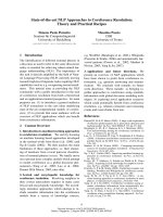
reliability. Figure 3.1 presents a flow diagram of a methodol-
ogy proposed as a guide in assessments of safety-related con-
crete structures in nuclear power plants (Naus et al. 1994).
The diagram is an adaptation of a procedure proposed to
evaluate the structural condition of buildings (Rewerts
1985).
This chapter provides information to rate the current
condition and assess remaining service life.
3.2—Evaluation of reinforced concrete aging or
degradation effects
Performance of a structure is measured by the physical
condition and functioning of component structural materials.
Tests are conducted on reinforced concrete to assess perfor-
mance of the structure as a result of (Murphy 1984):
• Noncompliance of properties with specifications;
• Inadequacies in placing, compacting, or curing of con-
crete;
• Damage resulting from overload, fatigue, freezing and
thawing, abrasion, chemical attack, fire, explosion, or
other environmental factors; or
• Concern about the capacity of the structure.
Testing is also undertaken for the verification of models,
materials, and environmental parameters used for calculating
the service life in the design phase. The validated or im-
proved models are then used for optimization of the building
operation and maintenance.
Prediction of the remaining service life of a concrete struc-
ture requires the accumulation of data such as depicted in Ta-
ble 3.1. Verification that the structural condition is as depicted
in the construction documents, such as drawings, determina-
tion of physical condition, quantification of applied loads, and
examination of any degradation are important. The questions
faced in predicting service life are: establishing how much
data should be accumulated, the desired accuracy of the pre-
dictions, available budgets for the predictive effort, as well as
subsequent levels of inspection, maintenance, and repair.
365.1R-12 ACI COMMITTEE REPORT
Chapter 2 indicates that the ability of a reinforced concrete
structure to meet its functional and performance requirements
over an extended period of time is largely dependent on the du-
rability of its components. Techniques for the detection of con-
crete component degradation should address the concrete,
steel reinforcement, and anchorage embedments.
3.2.1 Concrete material systems—Primary manifestations
of distress that can occur in reinforced concrete structures in-
clude cracking and delaminations (surface parallel cracking),
excessive deflections, and mechanical property (strength)
losses. Whether the concrete was batched using the proper
constituents and mixture proportioning, or was properly
Fig. 3.1— Concrete component evaluation methodology. Source: Adaptation of a procedure presented in Rewerts 1985.
Table 3.1—Example of types of information needed for service-life assessment
*
Conformance of structure to original design
Documentation review
Preliminary site visit
• Visual inspection for compliance with construction documents
• Pachometer (covermeter) survey to locate and characterize steel reinforcement (for example, size and spacing)
Preliminary analysis
Inspection for presence of degradation
Visual inspection
Crack survey
Delamination/spall survey
Chloride survey
Carbonation survey
Sample removal
Laboratory testing
Petrographic studies (for example, air content, air-void distribution, unstable aggregates, types of distress, and estimation of w/cm)
Chemical studies (for example, chemical constituents of cementitious materials, pH, presence of chemical admixtures, and characteristics of paste and
aggregates)
Concrete and steel reinforcement material properties (for example, strength and modulus of elasticity)
Degradation assessment
Current-versus-specified material properties
Concrete absorption and permeability (relative)
Concrete cover (for example, cores, or pachometer or covermeter measurements)
Presence of excessive concrete crack widths, spalling, or delaminations
Depth of chloride penetration and carbonation
Steel reinforcement corrosion activity (for example, half-cell potential measurements, and galvanostatic pulse, four-electrode, and corrosion probes
Environmental aggressivity (for example, presence of moisture, chlorides, and sulfates)
Structural reanalyses for current conditions
Reanalyses for typical dead and live loads
Examination of demands from other loads (for example, seismic and wind)
*This list is not all inclusive.
365.1R-13
SERVICE-LIFE PREDICTION—STATE-OF-THE-ART REPORT
Table 3.2—Nondestructive test methods for determining material properties of hardened concrete in
existing construction (ACI 228.2)
Property
Possible methods
CommentPrimary Secondary
Compressive strength
Cores for compression
testing
(ASTM C 42 and C 39)
Penetration resistance
(ASTM C 803; pullout testing
drilled in)
Strength of in-place concrete; comparison of
strength in different locations; and drilled-in
pullout test not standardized
Relative compressive strength
Rebound number (ASTM C 805);
ultrasonic pulse velocity
(ASTM C 597)
—
Rebound number influenced by near surface
properties; ultrasonic pulse velocity gives
average result through thickness
Tensile strength
Splitting-tensile strength of core
(ASTM C 496)
In-place pulloff test (ACI 503R;
BS 1881; Part 207)
Assess tensile strength of concrete
Density
Specific gravity of samples
ASTM C 642)
Nuclear gage —
Moisture content Moisture meters Nuclear gage —
Static modulus of elasticity
Compression test of cores
(ASTM C 469)
——
Dynamic modulus
of elasticity
Resonant frequency testing of
sawed specimens (ASTM C 215)
Ultrasonic pulse velocity
(ASTM C 597); impact echo;
spectral analysis of surface
waves (SASW)
Requires knowledge of density and Poisson’s ratio
(except ASTM C 215); dynamic elastic modulus
is typically greater than the static elastic modulus
Shrinkage/expansion
Length change of drilled or
sawed specimens (ASTM C 341)
— Measure of incremental potential length change
Resistance to chloride
penetration
90-day ponding test (AASHTO-T-259)
Electrical indication of con-
crete’s ability to resist chloride
ion penetration (ASTM C 1202)
Establishes relative susceptibility of concrete to
chloride ion intrusion; assess effectiveness of
chemical sealers, membranes, and overlays
Air content; cement content; and
aggregate properties (scaling,
alkali-aggregate reactivity, freez-
ing-and-thawing susceptibility
Petrographic examination of concrete
samples removed from structure
(ASTM C 856, ASTM C 457); Cement
content (ASTM C 1084)
Petrographic examination of
aggregates (ASTM C 294,
ASTM C 295)
Assist in determination of cause(s) of distress;
degree of damage; quality of concrete when
originally cast and current
Alkali-silica reactivity
Cornell/SHRP rapid test
(SHRP-C-315)
—
Establish in field if observed deterioration
is due to alkali-silica reactivity
Carbonation, pH
Phenolphthalein (qualitative
indication); pH meter
Other pH indicators
(for example, litmus paper)
Assess corrosion protection value of concrete
with depth and susceptibility of steel
reinforcement to corrosion; depth of carbonation
Fire damage
Petrography; rebound number (ASTM
C 805)
SASW; ultrasonic pulse
velocity; impact-echo; impulse-
response
Rebound number permits
demarcation of damaged concrete
Freezing-and-thawing damage
Petrography SASW; impulse response —
Chloride ion content
Acid-soluble (ASTM C 1152) and
water-soluble (ASTM C 1218)
Specific ion probe
(SHRP-S-328)
Chloride ingress increases susceptibility of steel
reinforcement to corrosion
Air permeability
SHRP surface airflow method
(SHRP-S-329)
—
Measures in-place permeability index of near
surface concrete (15 mm)
Electrical resistance of concrete
AC resistance using four-probe
resistance meter
SHRP surface resistance test
(SHRP-S-327)
AC resistance useful for evaluating effectiveness of
admixtures and cementitious additions; SHRP
method useful for evaluating effectiveness of sealers
placed, compacted, and cured are important because they can
affect the service life of the structure. Measurement of these
factors should be part of the overall evaluation process. In-
place permeability tests can also be conducted on concrete to
locate areas that are more susceptible to degradation.
3.2.1.1
Nondestructive test methods
—Nondestructive test
methods are used to determine hardened-concrete properties
and to evaluate the condition of concrete in structures. Table
3.2 and 3.3 present nondestructive test methods for determin-
ing material properties of hardened concrete in existing con-
struction and to determine structural properties and assess
conditions of concrete, respectively (ACI 228.2R). A descrip-
tion of the method and principle of operation, as well as appli-
cations, for the most commonly used nondestructive test
methods is provided elsewhere (ACI 228.1R, ACI 228.2R,
Bungey 1996, Malhotra 1984, Malhotra and Carino 1991).
3.2.1.2
Destructive test methods
—Visual and nonde-
structive testing methods are effective in identifying areas of
concrete exhibiting distress but often cannot quantify the ex-
tent or nature of the distress. This is generally accomplished
through removal of cores or other samples using a procedure
such as provided in ASTM C 42.
When core samples are removed from areas exhibiting dis-
tress, a great deal can be learned about the cause and extent of
deterioration through strength (Hindo and Bergstrom 1985)
and petrographic studies (ASTM C 856).
Additional uses of
concrete core samples include calibration of nondestructive
testing devices, conduct of chemical analyses, visual examina-
tions, determination of steel reinforcement corrosion, and de-
tection of the presence of voids or cracks (Munday and Dhir
1984, Bungey 1979).
3.2.1.3
Mixture composition
—The question of whether
the concrete in a structure was cast using the specified mix-
ture composition can be answered through examination of
core samples (Mather 1985). By using a point count method
(ASTM C 457), the nature of the air void system (volume
and spacing) can be determined by examining a polished sec-
tion of the concrete under a microscope. An indication of the
365.1R-14 ACI COMMITTEE REPORT
type and relative amounts of fine and coarse aggregate, as
well as the amount of cementitious matrix and cement con-
tent, can also be determined (ASTM C 856; ASTM C 85).
Determination of the original w/cm is not covered by a stan-
dard test procedure, but the original water (volume of capil-
lary pores originally filled with capillary and combined
water) can be estimated (BS 1881, Part 6). Thin-section anal-
ysis can also indicate the type of cementitious material and
the degree of hydration, as well as type and extent of degra-
dation. A standard method also does not exist for determina-
tion of either the type or amount of chemical admixtures used
in the original mixture. Determination of mixture composi-
tion becomes increasingly difficult as a structure ages, partic-
ularly if it has been subjected to leaching, chemical attack, or
carbonation.
3.2.2 Steel reinforcing material systems—Assessments of
the steel reinforcing system are primarily related to determin-
ing its presence and size, and evaluating the occurrence of cor-
rosion. Determination of material properties such as tensile
and yield strengths, and modulus of elasticity, involves the re-
moval and testing of representative samples. Pertinent nonde-
structive test methods that address the steel reinforcing
material system are provided in Table 3.2 and 3.3. ACI 222R
provides detailed information on the mechanism of corrosion
of steel in concrete and procedures for identifying the corro-
sion environment and active corrosion in reinforced concrete.
3.2.3 Anchorage embedments—Failure of anchorage em-
bedments in concrete structures occurs as a result of either
improper installation, cyclic loading, or deterioration of the
concrete. Visual inspections can evaluate the general condi-
tion of the concrete near an embedment and provide a curso-
ry examination of the anchor to check for improper
embedment, weld or plate tearing, plate rotation, or plate
buckling. Mechanical tests can verify that pullout and torque
levels of embedments meet or exceed values required by de-
sign. Welds or other metallic components can be inspected
using magnetic-particle or liquid-penetrant techniques for
surface examinations, or if a volumetric examination is re-
quired, radiographic, ultrasonic, and eddy current techniques
are available. ACI 355.1R, ACI SP-103, and ACI SP-130
provide additional information on anchorage to concrete.
3.3—Condition, structural, and service-life
assessments
3.3.1 Current condition—Determining the existing perfor-
mance characteristics and extent and causes of any observed
distress is accomplished through a condition assessment by
personnel having broad knowledge in structural engineering,
concrete materials, and construction practices. Several docu-
ments are available to aid in conducting a condition assess-
ment of reinforced concrete structures and components (ACI
201.1R; ACI 224.1R; ACI 437R; ACI 207.3R; ACI 311.4R;
ACI 362R; ASTM C 823; Bresler 1977; Perenchio 1989;
ASCE 11-90; Kaminetzky 1977).
The condition assessment
commonly uses a field survey involving visual examination
and application of nondestructive and destructive testing
techniques, followed by laboratory and office studies.
Guidelines for conduct of surveys of existing buildings have
been prepared (Perenchio 1989; ASCE 11-90).
Before con-
ducting a condition assessment, a definitive plan should be
developed to optimize the information obtained. The condi-
tion assessment begins with a review of the as-built drawings
and other information pertaining to the original design and
construction so that information, such as accessibility and
the position of embedded-steel reinforcement and plates in
the concrete, are known before the site visit. Next, a detailed
visual examination of the structure is conducted to document
information that could result from or lead to structural distress,
such as cracking, spalling, leakage, and construction defects,
such as honeycombing and cold joints, in the concrete. Photo-
graphs or video recordings made during the visual examina-
tion can provide a permanent record of this information.
Assistance in identifying various forms of degradation has
been prepared (ACI 201.1R).
After the visual survey has been
completed, the need for additional surveys, such as delamina-
tion plane, corrosion, or pachometer is determined. Results of
these surveys are used to select portions of the structure to be
Table 3.3—Nondestructive test methods to determine structural properties and assess conditions of
concrete (ACI 228.2)
Property
Methods
CommentPrimary Secondary
Reinforcement location
Covermeter; ground penetrating
radar (GPR) (ASTM D 4748)
X-ray and
γ
-ray radiography Steel location and distribution; concrete cover
Concrete component
thickness
Impact-echo (I-E);
GPR (ASTM D 4748)
Intrusive probing
Verify thickness of concrete; provide more certainty
in structural capacity calculations; I-E requires knowledge
of wave speed, and GPR of dielectric constant
Steel area reduction
Ultrasonic thickness gage
(requires direct contact with steel)
Intrusive probing; radiography
Observe and measure rust and area reduction in steel;
observe corrosion of embedded post-tensioning
components; verify location and extent of deterioration;
provide more certainty in structural capacity calculations
Local or global
strength and behavior
Load test, deflection or
strain measurements
Acceleration, strain, and
displacement measurements
Ascertain acceptability without repair or strengthening;
determine accurate load rating
Corrosion potentials
Half-cell potential
(ASTM C 876)
— Identification of location of active reinforcement corrosion
Corrosion rate
Linear polarization
(SHRP-S-324 and S-330)
—
Corrosion rate of embedded steel; rate
influenced by environmental conditions
Locations of
delaminations, voids,
and other hidden defects
Impact-echo; Infrared
thermography (ASTM D 4788);
impulse-response; radiography; GPR
Sounding (ASTM D 4580);
pulse-echo; SASW; intrusive
drilling and borescope
Assessment of reduced structural properties; extent and loca-
tion of internal damage and defects; sounding limited to
shallow delaminations
365.1R-15
SERVICE-LIFE PREDICTION—STATE-OF-THE-ART REPORT
studied in greater detail. Many of the investigation techniques
have been identified in the previous section. Any elements
that appear to be structurally marginal, due to either unconser-
vative design or effects of degradation, are identified and ap-
propriate calculation checks made (refer to Section 3.3.2). A
report is prepared after the field and laboratory results have
been collated and studied and calculations completed.
3.3.2 Structural assessment—Once the critical structural
components have been identified through the condition assess-
ment, a structural assessment can be required to determine the
current condition, to form the basis for estimating future per-
formance or service life, or both. As part of the assessment it
is important to note irregularities or inconsistencies in proper-
ties of materials, in design, in construction and maintenance
practices, and the presence and effects of environmental fac-
tors. Although the assessment of a structure involves more
than its load-carrying ability (for example, the permeability
of hydraulic structures), an assessment of structural demand
versus capacity is the first step. Performance requirements
other than structural capacity are then addressed through
supplementary tests to establish characteristics, such as leak-
age rate or permeability.
Procedures to evaluate the strength of existing structures
have been published (ACI 437R).
The recommendations de-
veloped are intended to establish the loads that can be sus-
tained safely and serviceably by an existing building under
several conditions:
• There is evidence of possible structural weakness (for
example, excessive cracking or spalling);
• The building or a portion of it has undergone general or
local damage (for example, environmental or earth-
quake effects);
• There is doubt concerning the structure’s capacity; and
• Portions of a building are suspected to be deficient in
design, detail, material, or construction.
Methods for strength evaluation of existing concrete struc-
tures include either an analytical assessment or a load test
(Fig. 3.2).
An analytical assessment is recommended when sufficient
background information is not available (for example, section-
al characteristics, material properties, and construction quali-
ty), a static load test is impractical because of the test
complexity or magnitude of the load required, sudden failure
during a static load test can endanger the integrity of the mem-
ber or the entire structure, or it is required by an authority.
Some supplemental destructive or nondestructive tests de-
scribed previously can be required to obtain this information.
For the evaluation it is recommended that the theoretical
analyses follow principles of strength design and that a struc-
ture be considered satisfactory if capacity, deformation, and
other serviceability criteria satisfy the requirements and in-
tent of the ACI 318.
Static-load tests should be utilized only when the analytical
method is impractical or otherwise unsatisfactory. Situations
where a static load test of a bridge or building component is
recommended include those where at least one of the following
cases and all of the following conditions apply (ACI 437R).
Cases include incidences where structural element details are
not readily available; deficiencies in details, materials, or con-
struction are best evaluated by a load test; and the design is ex-
tremely complex with limited prior experience for a structure
of this type. Conditions include: 1) results of a static load test
permit a reasonable interpretation of structural adequacy; 2)
principal structural elements under investigation are primarily
flexural members; and 3) adjacent structure’s effects can be ac-
counted for in the evaluation of the load test results. Before
conduct of a load test, some repair actions can be required and
an approximate analysis should be conducted. After establish-
ing the magnitude of the test load, the load is applied incremen-
tally with deflections measured. The structure is considered
to have passed the load test if it shows no visible evidence of
failure, such as excessive cracking or spalling, and it meets
requirements for deflection. In certain applications, service-
ability requirements, such as allowable leakage at maximum
load, can also be a criterion.
3.3.3 Service-life assessments—Any viable design method
or assessment of service life involves a number of essential
elements: a behavioral model, acceptance criteria defining
satisfactory performance, loads under which these criteria
should be satisfied, relevant characteristic material proper-
ties, and factors or margins of safety that take into account
uncertainties in the overall system (Sommerville 1992). The
selection of materials and mixture proportions, such as the
maximum w/cm, and structural detail considerations, pro-
vides one approach used for design of durable structures. An-
other approach entails prediction of service life using
calculations based on knowledge about the current damage,
Fig. 3.2—Recommended procedure for strength evaluation
of existing concrete buildings (ACI 437).
365.1R-16 ACI COMMITTEE REPORT
degradation mechanisms, and the rates of degradation reac-
tions. Development of a more comprehensive approach for
design of durable structures requires integration of results
obtained from a large number of studies that have been con-
ducted relative to concrete durability.
3.4—Inspection and maintenance
In-service inspection and preventive maintenance are a rou-
tine part of managing aging and degradation in many engi-
neered facilities (House 1987). The structural integrity of civil
structures, such as bridges and offshore platforms exposed to
extreme climatic conditions, are routinely assessed. These as-
sessments record performance and estimate the structure’s
ability to continue to meet functional and performance require-
ments. Also, in-service inspection and maintenance strategies
can be used to predict reliability and usable life of structures.
One approach to predicting the structure’s reliability or its
service life under future operating conditions is through
probability-based techniques involving time-dependent reli-
ability analyses. These techniques integrate information on
design requirements, material and structural degradation,
damage accumulation, environmental factors, and nonde-
structive evaluation technology into a decision tool that pro-
vides a quantitative measure of structural reliability. The
technique can also investigate the role of in-service inspec-
tion and maintenance strategies in enhancing reliability and
extending usable life. In-service inspection methods can im-
pact the structural reliability assessment in two areas, detection
of defects and modifications to the frequency distribution of
resistance. Several nondestructive test methods that detect the
presence of a defect in a structure tend to be qualitative in na-
ture in that they indicate the presence of a defect but may not
provide quantitative data about the defect’s size, precise lo-
cation, and other characteristics that would be needed to de-
termine its impact on structural performance. None of these
methods can detect a given defect with certainty. The imper-
fect nature of these methods can be described in statistical
terms. This randomness affects the calculated reliability of
a component. Figure 3.3 illustrates the probability, d(x), of
detecting a defect of size x. Such a statistical relation ex-
ists, at least conceptually, for each of the applicable in-ser-
vice inspection methods. In-service inspection methods
also provide information that allow the probabilistic
strength models used in reliability analyses to be revised
(Viola 1983, Turkstra et al. 1988, Ciampoli 1989, Bartlett
and Sexsmith 1991). The effect of in-service inspection on
the distribution of resistance is illustrated in Fig. 3.4. The
frequency distribution of resistance, based on prior knowl-
edge of the materials used to fabricate the structure, con-
struction, and standard methods of analysis, is indicated by
the curve f
R
(r) in the figure. Scheduled maintenance and
repair can cause the characteristics of the resistance to
change. The effect of inspection and maintenance is illus-
trated by the (conditional) density f
R
(r|B), in which B is de-
pendent on what is learned from the in-service inspection.
The in-service inspection probably causes the mean value
of the resistance distribution to increase because of basic
conservatism in structural design. Quantitative data on the
capabilities of in-service inspection methods are required for
determining the appropriate modifications to the frequency
distribution, f
R
(r), and to take optimum advantage of in-ser-
vice inspection in the reliability analysis.
Once it has been established that a component has been
subjected to environmental factors that have resulted in dete-
rioration, the effects of these factors can be related to a con-
dition or structural reliability assessment. Structural loads,
engineering material properties, and strength-degradation
mechanisms are random. The resistance, R(t), of a structure
and the applied loads, S(t), both are stochastic functions of
time. At any time, t, the margin of safety, M(t), is
(3-1)
Making the customary assumption that R and S are statisti-
cally independent random variables, the probability of fail-
ure, P
f
(t), is
(3-2)
in which F
R
(x) and f
S
(x) are the probability distribution func-
tion of R and density function of S. Equation (3-2) provides
one quantitative measure of structural reliability and perfor-
mance, provided that P
f
can be estimated and validated.
For service-life prediction and reliability assessment, the
probability of nonfailure over some period of time, (0,t), is
more important than the reliability of the structure at the par-
ticular time provided by Eq. (3-2). The probability that a
Mt() Rt() St()–=
P
f
t() P[Mt() 0<] F
R
x()f
s
x()xd
0
∞
∫
==
Fig. 3.3—Defect detectability function (Ellington and Mori
1992).
Fig. 3.4—Role of in-service inspection on strength distribu-
tion (Ellingwood and Mori 1992).
365.1R-17
SERVICE-LIFE PREDICTION—STATE-OF-THE-ART REPORT
structure survives during interval of time (0,t), is defined by
a reliability function, L(0,t). If n discrete loads S
1
, S
2
, , S
n
occur at times t
1
, t
2
, ,t
n
during (0,t), the reliability function
becomes
(3-3)
If the load process is continuous rather than discrete, this ex-
pression is more complex.
The conditional probability of failure within time interval
(t,t+
∆
t), given that the component has survived during (0,t),
is defined by the hazard function
(3-4)
which is especially useful for analyzing structural failures
due to aging or deterioration. For example, the probability
that time to structural failure, T
f
, occurs before a future
maintenance operation at t+
∆
t, given that the structure has
survived to t, can be evaluated as
(3-5)
The hazard function for pure-chance failures is constant.
When structural aging occurs and strength deteriorates, h(t)
charateristically increases with time as illustrated in Fig. 3.5.
Intervals of inspection and maintenance required as a con-
dition for continuing the service of a structure also can be de-
termined from the time-dependent reliability analysis. The
updated density of R following each inspection is
(3-6)
where K(r) is denoted the likelihood function and c is a nor-
malizing constant. The time-dependent reliability analysis
then is reinitialized using the updated f
R
(r|
Β
) in place of
f
R
(r). The update causes the hazard function to be discontin-
uous in time and lowers the failure probability in Eq. (3-5).
The effect of in-service inspection or repair on the hazard
function is also illustrated in Fig. 3.5.
Uncertainties in methods of in-service inspection or repair
affect the density f
R
(r|
Β
). A combination of methods is usu-
ally more effective from a reliability point of view than us-
ing one method. When there are limited resources, it is most
effective to select a few safety-critical elements and concen-
trate on them (Hookham 1991, Ellingwood and Mori 1993).
Optimal intervals of inspection and repair for maintaining a
desired level of reliability can be determined based on ex-
pected life-cycle cost. Preliminary investigations have found
that life-cycle costs are sensitive to relative costs of inspec-
tion, maintenance, and failure. If the cost of failure is an or-
der of magnitude larger than inspection and maintenance
costs, the optimal policy is to inspect at nearly uniform inter-
vals of time. Additional information on applying the meth-
odology to investigate inspection or repair strategies for
L 0 t,()PRt
1
() S
1
… Rt
n
() S
n
>,,>[]=
ht() dLln 0 t,()()dt⁄–=
PT[
f
t ∆tT
f
t]>+≤ 1 hx()xd
t
t
∆
t
+
∫
–exp–=
f
R
rB()Pr R r drB,+≤<[]PB[]⁄ cKf
R
r()==
reinforced concrete elements in flexure and shear has been
reported (Mori and Ellingwood 1993, 1994b).
CHAPTER 4—METHODS FOR PREDICTING THE
SERVICE LIFE OF CONCRETE
4.1—Introduction
The selection of concrete materials and mixture propor-
tions is usually based on empirical relationships between
concrete mixtures and laboratory and field performance.
This approach assumes that the concrete selected supports
the desired service life for the structure.
Another approach for selecting concrete involves predict-
ing service life using calculations based on likely degrada-
tion mechanisms that manifest in the structure and the
reaction rates of these mechanisms. While this approach is
not often used, it can have an increasingly important role in
selecting concrete because of applications that require signif-
icantly increased service lives, increased use of concrete in
harsh environments, the high cost of rebuilding and maintain-
ing the infrastructure, and the development of high-perfor-
mance concretes for which a record of long-term performance
is, as yet, not available. In addition, improved understanding
of the factors controlling the service life of concrete contrib-
ute to the development of more durable concretes.
Many service-life prediction methods focus on the effect of
one degradation process. Experience, however, has shown that
degradation results when one or more degradation processes
are operative or from the interaction of the environment and
loads (Hookham 1990). This synergistic effect complicates
service-life prediction for both new concrete structures where
environmental factors and loads may have not been well de-
fined, and existing structures where the contribution to degra-
dation by various influences is difficult to assess. Primary
factors that can limit the service life of reinforced concrete
structures include the presence of chlorides, carbonation, ag-
gressive chemicals, such as acids and sulfates, freezing-and-
thawing cycling, and mechanical loads, such as fatigue, vi-
bration, and local overloads. Typically, only one primary
factor limits the service life and is the focus of service-life
prediction. As limited information is available on the syner-
gistic effect when more than one factor is operative, this
chapter focuses on the prominent environmental influences
noted previously. An overview of methods for predicting the
service life of new and existing concrete along with some ex-
Fig. 3.5—Role of in-service inspection/repair in controlling
hazard function (Ellingwood and Mori 1992).
365.1R-18 ACI COMMITTEE REPORT
amples of their applications are presented. Examples illus-
trating the use of several of the service-life methods and
models are provided in Chapter 6.
4.2—Approaches for predicting service life of new
concrete
Methods that have been used for predicting the service
lives of construction materials include estimates based on ex-
perience, deductions from performance of similar materials,
accelerated testing results, mathematical modeling based on
the chemistry and physics of expected degradation process-
es, and applications of reliability and stochastic concepts
(Clifton and Knab 1989). Although these approaches are dis-
cussed separately, they often are used in combination.
4.2.1 Predictions based on experience—Semiquantitative
predictions of the service life of concrete are based on the ac-
cumulated knowledge from laboratory and field testing and
experience. This contains both empirical knowledge and
heuristics; collectively, these provide the largest contribution
to the basis for standards for concrete. It is assumed that if
concrete is made following standard industry guidelines and
practices, it will have the required life. This approach gives
an assumed service-life prediction. The concrete can perform
adequately for its design life, especially if the design life is
fairly short and the service conditions are not too severe. This
approach breaks down when it becomes necessary to predict
the service life of concrete that is required to be durable for a
time that exceeds our experience with concrete, when new or
aggressive environments are encountered, or when new con-
crete materials are to be used. Several examples have been
analyzed using this approach with the conclusion that expe-
rience or qualitative assessments of durability do not form a
reliable basis for service-life predictions and are only esti-
mates (Fagerlund 1985).
4.2.2 Predictions based on comparison of performance—
The comparative approach has not been commonly used for
concrete, but with a growing population of aging concrete
structures its use will increase. In this approach, it is assumed
that if concrete has been durable for a certain time, a similar
concrete exposed to a similar environment has the same life.
A problem with this approach is each concrete structure has
a certain uniqueness because of the variability in materials,
geometry, construction practices, and exposure to loads and
environments. Also, over the years, the properties of con-
crete materials have changed. For example, portland cements
are ground finer today than they were 40 years ago to achieve
increased early-age strength. This results in concrete with
lower density and higher permeability (Neville 1987).
An-
other problem with the comparison approach is the differ-
ence in the microclimates (environment at concrete surface)
can have unanticipated effects on the concrete’s durability.
In contrast, advances in chemical and mineral admixtures
have led to the development and use of concrete with im-
proved performance and durability. Therefore, comparing
the durability of old and new concrete is not straightforward,
even when conditions are as similar as possible.
4.2.3 Accelerated testing
4.2.3.1 Approach—Most durability tests for concrete use
elevated loads or more severe environments, such as a higher
concentration of reactants, temperature, and humidity, to ac-
celerate degradation. Accelerated testing programs, if prop-
erly designed, performed, and interpreted, can help predict
the performance and service life of concrete. Accelerated
testing has been proposed as a method for predicting the ser-
vice life of several types of building materials (Frohnsdorff
et al. 1980). The degradation mechanism in the accelerated
test should be the same as that responsible for the in-service
deterioration. If the degradation proceeds at a proportional
rate by the same mechanism in both accelerated aging and
long-term in-service tests, an acceleration factor, K, can be
obtained, from
(4-1)
where R
AT
is the rate of degradation in accelerated tests, and
R
LT
is the rate of degradation in long-term in-service testing.
If the relationship between the rates is nonlinear, then math-
ematical modeling of the degradation mechanism is recom-
mended to establish the relationship.
ASTM E 632 gives a recommended practice for develop-
ing accelerated short-term tests that can obtain data for mak-
ing service predictions and for solving service-life models.
The practice consists of four main parts: problem definition,
pretesting, testing, and interpretation and reporting of data.
Application of this practice to concrete has been discussed
(Clifton and Knab 1989).
A difficulty in using accelerated testing in predicting ser-
vice life is the lack of long-term data on the in-service per-
formance of concrete as required in Eq. (4-1). Accelerated
tests, however, can provide information on concrete degra-
dation that is needed to solve mathematical models for pre-
dicting service lives.
4.2.3.2 Application—An example of the application of
accelerated testing service-life predictions is provided below
(Vesikari 1986). In this application, the lifetime of a speci-
men in an accelerated test t
*
is related to the service life of a
structure t
1
by
(4-2)
where k is a constant that is derived from testing. This ap-
proach is then applied to freezing-and-thawing resistance
testing of concrete as follows. In an accelerated freezing-
and-thawing test, the performance of a specimen is ex-
pressed in terms of the number of freezing-and-thawing cy-
cles needed to obtain a specified damage level. Assuming the
number of freezing-and-thawing cycles that a structure is
subjected to annually is constant, the service life of the struc-
ture can be evaluated by
(4-3)
where
k
e
= a coefficient related to environmental conditions;
and
KR
AT
R
LT
⁄=
t
1
kt
∗
=
t
1
k
e
N=
365.1R-19
SERVICE-LIFE PREDICTION—STATE-OF-THE-ART REPORT
N = number of freezing-and-thawing cycles damaging
a laboratory specimen.
This approach was further developed to predict the life of
concrete that is exposed to the combined effect of freezing-
and-thawing and salt-scaling action. In this case, the service
life was given by
(4-4)
where P is the freezing-and-thawing resistance index and is
obtained by the Deutscher Beton Verein (DBV) freeze-salt
test (Vesikari 1986). Values of the environmental factor k
f
are
based on field investigations that analyze the correlation be-
tween the degree of damage of the structure, age of the struc-
ture, and the freezing-and-thawing resistance of the structure.
The following study illustrates the application of an accel-
erated test method to estimate the service life of concrete ex-
posed to sulfate salts. The U.S. Bureau of Reclamation
combined the results of accelerated tests and long-term tests
(Kalousek et al. 1972). In the long-term tests, concrete spec-
imens were continuously immersed in a 2.1% sodium sulfate
(Na
2
SO
4
) solution until failure occurred, defined as an ex-
pansion of 0.5%, or until the investigation was completed.
The age of specimens at the completion of the continuous-
immersion study ranged from 18 to 24 years. Companion
specimens were subjected to an accelerated test in which the
specimens were exposed to repeated cycles of immersion in
a 2.1% sodium sulfate (Na
2
SO
4
) solution for 16 h and forced
air drying at 54 C for 8 h. Comparing the times for speci-
mens to reach an expansion of 0.5% in the accelerated test
and the continuous immersion test, it was estimated that one
year of accelerated testing was equivalent to eight years of
continuous immersion. In this case, Eq. (4-1) becomes
(4-5)
where
R
AT
= rate of expansion in the accelerated test, and
R
LT
= rate of expansion in the long-term continuous im-
mersion test.
A 2.1% solution of sodium sulfate (Na
2
SO
4
) is a severe en-
vironment and if concrete is exposed to a lower concentra-
tion of sulfate, the life expectancy would be expected to be
longer. This method can be used to predict the service life of
concrete continuously immersed in a different concentration
of sulfate ions, provided the acceleration factor is known.
4.2.4 Mathematical models—Mathematical models are no
better than their underlying conceptual base, so any solution
calculated using a model has uncertainties related to the
model as well as the material and environmental parameters.
Several models have been developed to predict the service
life of concrete subjected to degradation processes such as
corrosion, sulfate attack, leaching, and freezing-and-thaw-
ing damage (Clifton 1991). The use of mathematical models
to predict service life of concrete has been discussed (Pom-
mersheim and Clifton 1985). Models used to predict service
life of concrete used in the construction of underground
t
1
k
f
P=
K 8 R
AT
R
LT
⁄==
vaults for the disposal of low-level nuclear waste, which are
subjected to sulfate attack, corrosion of reinforcement, leach-
ing, and freezing-and-thawing attack, have been reviewed
(Walton et al. 1990). Many of the degradation processes of
concrete, excluding those caused by mechanical loads, are as-
sociated with the intrusion into concrete of one or more of the
following: water, salts, or gases. For such processes, mathe-
matical models that predict service life can be developed by
considering the rate of intrusion of aggressive media into con-
crete and the rate of chemical reactions and physical process-
es. Mathematical models have been developed for degradation
processes controlled by the intrusion of water, salts, and gases
into concrete by convection and diffusion (Pommersheim and
Clifton 1990). Most models that predict service life include
numerical variables related to transport processes, such as the
chloride ion diffusion coefficient in corrosion models. Stan-
dard methods have been developed for testing nonsteady state
water flow in concrete (Kropp and Hilsdorf 1995).
Further-
more, methods for testing ion diffusion, such as chlorides, are
also available (Nord Test 1995).
Reliable data on transport
properties, however, often are not available and standard
ASTM test methods have not been developed.
4.2.4.1 Model of corrosion of reinforcing steel—Most
corrosion models for reinforced concrete follow the same ap-
proach, and are based on a model that has been developed to
predict the service life of reinforcing steel (Tuutti 1982). The
model is based on the corrosion sequence schematically
shown in Fig. 4.1, in which active corrosion (propagation pe-
riod) starts after the end of an initiation period of no corro-
sion. The corrosion process is initiated by the diffusion of
chloride ions to the depth of the reinforcing steel or by car-
bonation reducing the pH of the concrete in contact with the
steel or by the combination of chloride ions and carbonation.
Other transport properties are not covered by the model.
Sorption could be another important transport process that
also follows a t
1/2
dependence, where t is time. Cracking of
the concrete would increase the diffusion coefficient and
sorptivity of the concrete, thus accelerating corrosion.
In the following, only the effect of chloride ions on the ini-
tiation period is considered. The length of the initiation peri-
od is largely controlled by the rate of diffusion of the
chloride ions in the concrete and by the threshold concentra-
tion for the process. The one-dimensional diffusion process
follows Fick’s second law of diffusion (Tuutti 1982)
(4-6)
where
D = diffusion coefficient;
x = distance from the concrete surface to the steel rein-
forcement; and
t = time.
Because chloride ions react with the tricalcium aluminate of
portland cement, the concentration has two components —
concentration of bound chloride ions (c
b
) and concentration
of free ions (cf), related through R
∂c
f
/ ∂tD∂
2
c
f
∂x
2
⁄=
365.1R-20 ACI COMMITTEE REPORT
(4-7)
Because either carbonation or sulfate ions can release the
bound chloride ions, R is usually assumed to be 0.
According to Tuutti’s model, the corrosion rate in the
propagation period is controlled by the rate of oxygen diffu-
sion to the cathode, resistivity of the pore solution, and tem-
perature. The initiation period is usually much longer than
the propagation period. For example, in one bridge deck the
initiation period has been estimated to be over five times
longer than the propagation period (Tuutti 1982). A conser-
vative estimate of the service life is usually made by only
considering the initiation period. If the concrete is continu-
ously saturated with water, the model predicts that corrosion
processes active in the propagation period become the rate-
controlling processes because of the extremely low diffusion
rate of oxygen through the water. A conceptually similar but
more complex model has been developed that predicts that
reinforced concrete submerged in seawater can be unaffected
by corrosion for thousands of years due to the absence or low
level of oxygen present (Ba
ž
ant 1979, 1979a).
The concepts of Tuutti’s model have been used to predict
the effects of the chloride-ion diffusion coefficient and the
depth of cover on the length of the initiation period (Clifton et
al. 1990). The period to initiate corrosion of a reinforced con-
crete element is determined as follows: C
0
is the concentration
of chloride ions at the outside surface of the concrete, and C
i
is
the concentration at the depth of the reinforcement, that is
assumed to be initially 0. The initiation period is completed
when C
i
= C
t
, the threshold concentration to initiate steel
reinforcement corrosion. The general solution to Eq. (4-6)
for a reinforced concrete element under constant environ-
mental conditions is
(4-8)
c
b
Rc
f
⋅=
C
C
0
Zt,()=
1
n
–()erfc
2n 1+()y–
2 r
erfc
2n 1+()y+
2 r
+
n
0=
∞
∑
where
erfc = complement of error function (Crank 1975);
y =(L-x)/L;
r = Dt/L
2
;
t = time;
n = general solution, summation of all
possible terms;
D = diffusion coefficient;
x = effective concrete cover depth
(for example, uncracked thickness); and
L = thickness of concrete element.
In the present case, however, only the n = 0 term of Eq. (4-8)
needs to be considered. Higher-order terms have insignificant
contributions to the summation, reducing the equation to
(4-9)
where 1 – y = x/L. The model was solved for the case where
the threshold concentration C
t
of chloride ions was 0.4%
(based on the mass of the cement), the concentration of chlo-
ride ions at the surface of the concrete C
o
was 0.7% (based
on the mass of cement), x = 50 mm, L = 300 mm, and C
i
= 0
at t = 0. Results for different concrete cover depths and chlo-
ride ion diffusivity coefficients are presented in Table 4.1.
The results show that the effect of the cover is proportional
to x
2
. For example, increasing x from 25 to 100 mm increases
the service life by a factor of (100/24)
2
or 16. The model also
predicts that a 10-fold decrease in the diffusion coefficient
results in a 10-fold increase in the predicted service life. Al-
though laboratory estimations of diffusion coefficients are too
conservative for accurate estimates of the life of reinforced
concrete, they do indicate the relative effects of important ma-
terial and design variables on service lives.
Different solutions to Fick’s second law have been devel-
oped to evaluate concrete under environmental conditions
that vary with time (Amey et al. 1998). In such cases, the sur-
face chloride concentration also changes with time (for ex-
ample, by the application of chloride deicing salts). To obtain
a relation that allows a surface build-up of chlorides, an equa-
tion other than Eq. (4-9) should be used due to the change in
boundary conditions. Although there is no conclusive evi-
dence for what function Φ(t) should be assigned to represent
that build-up, there is some intuitive support for a linear or
C
C
0
erfc
1 y–()
2 r
=
Fig. 4.1—Schematic of conceptual model of corrosion of
steel reinforcement in concrete (Tuutti 1982).
Table 4.1—Effect of cover and diffusion coefficient
on time to initiation of corrosion of reinforced
concrete
Cover, mm
Chloride ion diffusion coefficient D, m
2
/s
*
5
×
10
¯11
5
×
10
¯12
5
×
10
¯13
Time, yr
25 0.56 5.6 56
50 2.3 23.0 230
75 5.0 50.0 500
100 9.0 90.0 900
*
Based on setting
C
t
/
C
0
= 0.55, with
C
t
= 0.4% (by mass cement), and
L
= 300 mm.
365.1R-21
SERVICE-LIFE PREDICTION—STATE-OF-THE-ART REPORT
square root build-up of chloride over time. For the case where
Φ(t) = kt, where k is a constant under a linear build-up condi-
tion, the following simplified solution should be used
(4-10)
where erfc ( ) = the complementary error function. For the
case where Φ(t) = kt
1/2
, where k is a constant under a square
root build-up condition, the following simplified solution
should be used
(4-11)
Equations (4-10) and (4-11) are most suited for evaluating
air-borne deicing salts applications. Additional information
on models can be obtained from Vesikari (1988), who de-
scribes mechanistic models empirically fitted to data from
field and laboratory studies, and HETEK (1996). Corrosion
induced by chloride ions and by carbonation is addressed, and
both the initiation and propagation periods are modeled.
These models are useful in identifying the factors controlling
the service life of reinforced concrete when corrosion is the
major degradation process. They are solved using empirically
derived coefficients for the quality of concrete, environments,
and intensity of active corrosion. Effects of different types of
cements, extent of carbonation, and compressive strength of
concrete on corrosion are considered by the coefficient for the
quality of concrete. The reliability of these models when pro-
jected to other concretes and environments needs to be deter-
mined before they are used.
Probabilistic models and computational methods for chlo-
ride ingress in concrete have also been developed (Engelund
1977).
4.2.4.2 Sulfate attack—A mechanistic model has been
developed to predict the effect of ground water containing
sulfates on the service life of concrete (Atkinson and Hearne
1990). The model is based on the following:
• Sulfate ions from the environment penetrate the con-
crete by diffusion;
• Sulfate ions react expansively with aluminates in the
concrete; and
• Cracking and delamination of concrete surfaces result
from the expansive reactions.
Cracking and delamination of the concrete surface ex-
poses new surfaces to a concentration of sulfate ions similar
to that of the ground water sulfate concentration rather than
the lower concentration resulting from diffusion. The model
indicates that the rate of sulfate attack is controlled by the
concentration of sulfate ions and aluminates, diffusion and
reaction rates, and the fracture energy of concrete. Relation-
Cxt,()=
kt 1
x
2
2Dt
+
erfc
x
2 Dt
x
πDt
e
x
2
4
Dt
⁄
–
–
Cxt,() kte
x
2
4
Dt
⁄
–
x π
2 Dt
erfc
x
2 Dt
–
=
ships are developed for reaction kinetics, the concentration
of reacted sulfate in the form of ettringite, the thickness of a
spalled concrete layer, the time for a layer to spall, and the
degradation rate. The depth of degradation (R) is linear in
time, that is, m/sec, and is given by
(4-12)
where
X
spall
= the thickness of the reaction zone causing the
spalling;
T
spall
= the time for the spall to occur;
E = Young’s modulus;
B = the linear strain caused by a concentration
of sulfate reacted in a specific volume of
concrete (such as 1 mole of sulfate reacted
in 1 m
3
of concrete);
c
s
= the sulfate concentration in bulk solution;
C
0
= the concentration of reacted sulfate in
the form of ettringite;
D
i
= the intrinsic diffusion coefficient of
sulfate ions;
α
0
= roughness factor for fracture path;
τ
= the fracture surface energy of concrete; and
ν
= Poisson’s ratio.
Some of the input data required to solve the model should
be obtained from laboratory experiments, while some of the
parametric values are not available for specific concretes and
therefore typical values should be used. In the example cal-
culation (Atkinson and Hearne 1990), the rate of attack for a
sulfate-resistant portland cement (similar to ASTM C 150
Type V) was predicted to be only about 30% lower than that
for ordinary portland cement (similar to ASTM Type I). The
results agree with the generally accepted view that the per-
meability of the concrete (reflected in the sulfate diffusion
coefficient) is more important in controlling sulfate attack
than the chemical composition of the cement.
4.2.4.3 Leaching—A leaching model for the dissolution
of gypsum and anhydrite (James and Lupton 1978) has been
used to predict the rate of dissolution of portland-cement
mortar exposed to flowing water (Jones 1989). It has the form
(4-13)
where
M = the mass lost in time t from an area A;
K = the experimentally obtained dissolution-rate con-
stant (linearly dependent on the flow velocities
within laminar flow regimes);
C
s
= the solution potential of water;
C = the concentration of dissolved material
at time t; and
θ
= the kinetic order of the dissolution process.
The rate of dissolution of both silica and calcium from
portland cement mortar was experimentally determined to
give second-order kinetics. A loss of 0.8 mm/yr of mortar
RX
spall
T
spall
⁄ EB
2
c
s
C
0
D
i
()α
0
τ 1 v–()[]⁄==
dM dt⁄ 2.6KA C
s
C–()
θ
=
365.1R-22 ACI COMMITTEE REPORT
was predicted at a flow velocity of 3 m/s, which is in reason-
able agreement with the measured loss of 1 mm/yr at flow of
3m/s.
4.2.5 Stochastic methods—The use of stochastic concepts
in making service-life predictions of construction materials
has been explored by several researchers (Sentler 1984;
Martin 1985). Service-life models using stochastic methods
are based on the premise that service life cannot be precisely
predicted (Siemes et al. 1985). A large number of factors af-
fect the service life of concrete, and their interactions are not
well known. These factors include the extent of adherence to
design specifications, variability in the properties of hard-
ened concrete, randomness of the in-service environment,
and a material’s response to microclimates. Two stochastic
approaches are the reliability method and the combination of
statistical and deterministic models.
4.2.5.1 Reliability method—The reliability method com-
bines the principles of accelerated degradation testing with
probabilistic concepts in predicting service life. This method
has been discussed (Martin 1985) and applied to coatings
(Martin 1989) and roofing materials (Martin and Embree
1989).
Application of the method is described by considering
concrete subjected to a hypothetical laboratory durability test.
As is typical of any engineering material, supposedly iden-
tical concrete specimens exposed to the same conditions
have time-to-failure distributions. The reliability method
takes into account the time-to-failure distributions. By ele-
vating the stresses that effect accelerating failure, probability
of failure functions can be obtained, as shown in Fig. 4.2.
These failure probabilities are based on the premise that time-
to-failure data follow a Weibull distribution (Martin 1985).
Testing multiple specimens is required to obtain the distribu-
tion. If the failure rate increases as the stress level increases,
the service life distribution at in-service stresses can be relat-
ed to the service-life distribution at elevated stress by the time
transformation function p
i
(t) as follows (Martin 1985)
(4-14)
where t is time, F
i
(t) is the life distribution at the i'th elevated
stress level, and F
o
(t) is the service-life distribution at the in-
service stress level. From Eq. (4-14), a probability of failure
stress time-to-failure (P-S-T) diagram can be prepared as
shown in Fig 4.3. The curves in the P-S-T diagram, such as
the F(t) = 0.10 curve, are iso-probability lines. The iso-prob-
ability lines give, for each stress level, the time at which a
given percent of a group of specimens can be expected to
have failed. The P-S-T diagram gives a basis to predict the
service life of concrete if the in-service conditions are in the
range covered by the diagram and are not anticipated to
change significantly.
The time-transformation function approach is applicable if
the deterioration mechanism under all tested stress levels is
the same as that under in-service conditions. Deterioration
begins at the instant of stress application, and deterioration is
an irreversible cumulative process.
4.2.5.2 Combination of statistical and deterministic
models—Often, statistical models are combined with deter-
ministic models. For example, the mean service life of build-
ings has been predicted by using mean values for the
parameters in deterministic models that have been developed
(Siemes et al. 1985). The standard deviation of the service
life is also calculated using the expression
(4-15)
where
σ
(t
1
) = standard deviation of service life;
σ
(x
j
) = standard deviation of the variables x
j
affecting ser-
vice life;
∂
t
1
/
∂
x
j
= partial derivative of t
1
with respect to x
j
; and
n = number of variables.
The partial derivatives,
∂
t
1
/
∂
x
j
, are calculated for the mean
values of the stochastic variables. In this approach, it is as-
sumed that the x
j
variables are independent of each other.
Instead of normal distributions, log-normal distributions are
recommended for representing the service-life distributions
(Siemes et al. 1985). A model for carbonation has been devel-
oped that demonstrates application of the stochastic method
F
i
t() F
o
p
i
t()()=
σ
2
t
1
()
∂
t
1
∂
x
1
x
i
()⋅
2
j
1=
n
∑
=
Fig. 4.2—Probability of failure at different stress levels
(Martin 1985).
Fig. 4.3—Probability of failure stress-to-failure (P-S-T) dia-
gram showing 10% probability of failure curve (Martin
1985).
365.1R-23
SERVICE-LIFE PREDICTION—STATE-OF-THE-ART REPORT
(Sentler 1984). The depth of carbonation x in concrete was
represented by the following form of Fick’s diffusion law
(4-16)
where
D = diffusion coefficient;
a = concentration of concrete constituents that can
carbonate;
dp = partial pressure difference for CO
2
; and
t =time.
When represented as a stochastic process the depth of carbon-
ation is expressed by
(4-17)
which is a normal density function f with mean, x
o
+ µt
1/2
,
and variance,
σ
2
t
1/2
. The initial value of x, x
0
, accounts for
faster carbonation taking place in the concrete surface layer.
Equation (4-17) gives the same mean rate of carbonation as
Eq. (4-16), but with variability in the depth of carbonation
determined by a normal density function. The model was
solved for a case where the concrete cover over steel rein-
forcement was 25 mm, the concrete had a w/cm of 0.5, and
the concrete had carbonated for 50 years. An initial fast car-
bonation was assumed (x
0
= 3 mm). The statistical parame-
ters were based on data obtained during a field study of the
relationship between the w/cm and depth of carbonation in
mm/yr
1/2
. Approximately 16% of the data were more than
one standard deviation from the mean value, indicating a
normal distribution. A probability of 2.3 × 10
–4
for carbon-
ation at 25 mm after 50 years was obtained. If the w/cm was
increased to 0.6, the probability becomes 3.3 × 10
–2
.
4.3—Prediction of remaining service life
Although the methods for predicting the remaining ser-
vice life of existing concrete structures are basically the
same as those for new structures, the existing structures can
have the benefit of additional information available (for ex-
ample, derived material properties and environmental ef-
fects). Methods for predicting the remaining service lives of
concrete structures usually involve the following general
procedures: determining the condition of the concrete, iden-
tifying the cause(s) of any concrete degradation, determin-
ing the condition constituting the end-of-service life of the
concrete, and making some type of time extrapolation from
the present state of the concrete to the end-of-service life
state to establish the remaining service life.
4.3.1 Failure due to corrosion—Most of the reported
work on predicting remaining service lives of reinforced
concrete structures has dealt with corrosion of the concrete
reinforcement. Two major prediction approaches that have
been pursued are the modeling approach and corrosion mea-
surements.
x
2
2Da⁄()dp t⋅=
f
xx
0
t;,()
1
σ 2πt
12
⁄
()
12
⁄
xx
0
– µt
12
⁄
–()
2
2σ
2
t
12
⁄
exp=
4.3.1.1 Modeling approach—The modeling approach is
illustrated by the work of Browne (1980). He used a diffusion-
based model for predicting the remaining service life of in-ser-
vice reinforced concrete structures exposed to chloride ions.
The model only considers the initiation period (Fig. 4.1) and
assumes that the diffusion of chloride ions is the rate-con-
trolling process. The following steps help make predictions
about the service life:
• Samples are obtained from a concrete structure at dif-
ferent depths from the concrete surface and their chlo-
ride contents determined; and
• The following equation is used to obtain values of C
0
and D
cl
(4-18)
where
C(x,t) = chloride concentration at depth x after time t, for
a constant chloride concentration of C
0
at the
surface;
D
cl
= chloride ion diffusion coefficient; and
erf = error function.
• Once the values of C
0
and D
cl
are obtained, then the
chloride-ion concentration at any distance from the sur-
face, at any given time, can be calculated; and
• A chloride ion concentration of 0.4%, based on mass of
cement, is used by Browne (1980) as the threshold
value. The time to reach the threshold concentration at
the depth of the reinforcing steel gives the remaining
service life.
4.3.1.2 Corrosion measurements—The measurement of
corrosion current density of steel reinforcement in concrete
has been used (polarization resistance technique) in estimat-
ing the remaining service life of reinforced concrete in which
corrosion is the limiting degradation process (Rodriquez and
Andrade 1990; Andrade et al. 1989; Andrade et al. 1990;
Clear 1989).
Rodriquez and Andrade (1990) and Andrade et al. (1989,
1990) modeled corrosion current density to estimate the re-
maining service life. The model measures reduction in steel
cross section instead of cracking or spalling of the concrete.
The corrosion current density was converted to reductions in
the diameter of reinforcing steel by the relationship
(4-19)
where
θ(t) = steel reinforcement diameter at time t, mm;
θ
i
= initial diameter of the steel reinforcement, mm;
i
corr
= corrosion rate (µA/cm
2
);
t = time after the beginning of the propagation period,
years; and
0.023 = conversion factor of µA/cm
2
into mm/yr.
The results were converted into service-life predictions by
modeling the effects of reducing the cross section of the re-
inforcement on the load capacity of the reinforced concrete.
Cxt,() C
0
1 erf x 2 D
cl
t()
12
⁄
⁄()–[]=
θ t() θ
i
0.023
∗
i
corr
∗
t–=
365.1R-24 ACI COMMITTEE REPORT
Based on the combination of laboratory, outdoor exposure,
and field studies, Clear (1989) suggested using the following
relationships (that assume constant corrosion rates with time)
between corrosion rates i
corr
and remaining service life:
• i
corr
less than 0.5 µA/cm
2
—no corrosion damage
expected;
• i
corr
between 0.5 and 2.7 µA/cm
2
—corrosion damage
possible in the range of 10 to 15 years;
• i
corr
between 2.7 and 27 µA/cm
2
—corrosion damage
expected in 2 to 10 years; and
• i
corr
in excess of 27 µA/cm
2
—corrosion damage
expected in 2 years or less.
4.4—Predictions based on extrapolations
The remaining service life of a concrete structure or element
can be predicted from knowing its present condition and ex-
trapolating to when it needs extensive repair, restoration, or
should be replaced. The problem is to make the proper extrap-
olation starting from its condition at inspection to a condition
that is used to define end-of-service life.
Rather than making an empirical extrapolation, the time-
order approach gives a technical basis for the extrapolation
(Clifton 1991).
This approach has been previously used for
diffusion processes, for example, those involving depth of
carbonation or chloride ion diffusion. In the following, the
basis for the approach is given.
The amount of degradation of concrete is dependent on the
environment, geometry of the structure, properties of the
concrete, the specific degradation processes, and the concen-
tration of the aggressive chemical(s). In the time-order ap-
proach, these factors are constant and can be represented by
a term k
d
(Pommersheim and Clifton 1990). Climate changes
each season, but usually the variation between years
smoothes out over several decades. If this assumption is val-
id, then only the number of service years need to be repre-
sented by the time function t
y
, and k
d
has an average value
over the period considered. Implicit in this analysis is that the
same degradation process(es) is active during the past and fu-
ture life of the concrete.
In this approach, the amount of degradation A
d
can be rep-
resented by (Clifton 1991)
(4-20)
where
A
d
= amount of accumulative deterioration at time t
y
,
(years); and
n = time order.
Note that if n = 0, there is no degradation. If an initiation period
has occurred and its duration is known, then the right-hand side
of Eq. (4-20) would be k
d
(t
y
-t
o
)
n
, with t
o
being the duration of
the initiation period. In the development of the approach, the
term time order has been used to avoid confusion with the order
of a chemical reaction, for example, a second-order reaction
that can indicate that two molecules react together.
The overall rate of degradation, R
d
is given by
A
d
k
d
t
y
n
=
(4-21)
Equation (4-21) indicates that when n < 1, the rate of degra-
dation decreases with time; when n = 1, the rate is constant;
and when n > 1, the rate increases with time.
Defining A
df
as the amount of damage at failure, it follows
from Eq. (4-21) that
(4-22)
where t
yf
is the time-to-failure. The remaining service life is
obtained by subtracting the age of the concrete when the in-
spection was made from t
yf
.
The value of n depends on the rate-controlling process. It
can be obtained by a theoretical analysis of rate-controlling
processes, mathematical modeling of degradation processes,
and empirically from accelerated degradation tests (Clifton
1991; Clifton and Pommersheim 1994). Values of n for com-
mon degradation processes are available (Clifton and Pom-
mersheim 1991). Examples of using the time order approach
for predicting remaining service lives are also available
(Clifton 1991; Clifton and Pommersheim 1994).
4.5—Summary
Methods that are used for predicting the service lives of
construction materials include estimates based on experi-
ence, deductions from performance of similar materials, ac-
celerated testing, applications of reliability and stochastic
concepts, and mathematical modeling based on the chemis-
try and physics of degradation processes. Often these ap-
proaches are used in combination. The most promising
methods are accelerated testing, applying reliability and sto-
chastic concepts, and using mathematical models.
In comparison to predicting the life of new concrete, few
studies on predicting the remaining service life of in-service
concrete have been reported. Most of the reported studies
have dealt with corrosion of concrete reinforcement, reflect-
ing the magnitude and seriousness of corrosion problems.
The most promising approach for predicting the remaining
service life of concrete involves applying mathematical
models to the degradation process. Theoretical models
should be developed, rather than relying solely on empirical
models. Many advantages of this approach are apparent, in-
cluding more reliable predictions, less data needed, and wid-
er applications, such as applicability to a broad range of
environmental conditions. Deterministic and stochastic mod-
els should be combined to give realistic predictions of the ser-
vice life. Purely stochastic models have limited application
because of the lack of adequate databases that determine sta-
tistical parameters. Accelerated tests do not provide a direct
method for making the life predictions but can be useful in ob-
taining data required to support the use of analytical models.
CHAPTER 5—ECONOMIC CONSIDERATIONS
5.1—Introduction
The development of new facilities in both the public and pri-
vate sectors, as well as existing concrete structures and facili-
R
d
nk
d
t
y
n
1–
=
t
yf
A
df
k
d
⁄()
1
n
⁄
=
365.1R-25
SERVICE-LIFE PREDICTION—STATE-OF-THE-ART REPORT
ties, requires decisions based on economics and service-life
(or life-cycle) information.
‡
Some of the questions that are en-
countered in making these service-life decisions include:
• Are higher initial construction capital investments jus-
tified to obtain longer service life?
• Are higher initial construction capital investments jus-
tified to reduce operating or maintenance costs?
• Are higher annual inspection and maintenance costs jus-
tified to increase the service life of an existing facility?
• Should outdated facilities be replaced with facilities
requiring less frequent, less costly periodic mainte-
nance?
• Should an existing facility be repaired or replaced to
reduce day-to-day operating and maintenance costs, or
to increase its safety margin?
Service life and pertinent costs are the key elements when
addressing these questions. In the above context, service life
refers to the effective period for subroutines, such as periodic
rehabilitation, as well as the system as a whole. Selecting
technically feasible alternatives that result in the minimum
overall cost for the defined planning horizon constitutes the
scenario for minimum life-cycle cost policy in facilities
management. It is, then, the effects of serviceability (or ser-
vice life) on cash flow over time that constitute the basis for
rational management of facilities and assets.
5.2—Economic analysis methods
5.2.1 General—Economic analysis is a tool for making
rational decisions in engineering situations where a choice
should be made from a group of alternatives with differences
that can be expressed in monetary terms. The first two steps
involved in an engineering economic analysis are the same for
all economic analysis methods. First, all technically feasible
alternatives that are applicable should be identified. Doing
nothing can constitute a viable alternative. Second, cash-flow
elements need to be costed-out and time-based cash flow dia-
grams prepared. In carrying out the latter, a target economic
service-life period (planning horizon) needs to be established
in which all the cost alternatives are evaluated. Therefore, en-
gineering economic analysis can be used to make decisions
affecting the service life of a concrete structure.
5.2.2 Methods—Once the alternatives and their respective
cash flows have been established, a variety of techniques exist
whereby the analysis can be carried out. All analyses should
provide the same result in terms of the selection of alterna-
tives, but the nature of the scenario in which the alternatives
are being evaluated can favor the use of a particular proce-
dure. ASTM E 1185, describes the following five methods:
• Life-cycle cost (LCC)—Provides the equivalent of the
relevant cash flow in either present-value or annual-
value terms for each alternative over the selected plan-
ning horizon. The details are presented in ASTM E
917.
• Benefit-to-cost ratio (BCR)—Provides a ratio of bene-
fit and cost items that can be quantified in monetary
terms for each alternative, based on equivalent values
expressed in either present or annual value. The details
are presented in ASTM E 964.
• Internal rate of return (IRR)—Provides the interest rate
at which the equivalent net cash flow (expressed in
terms of either present or annual value) equals zero for
comparing alternatives and for comparison with the
acceptable discount rate or desired rate of return. The
details are presented in ASTM E 1057.
• Net benefits (NB)—Provides the difference between
benefit and cost (including disbenefit) items that can be
expressed in monetary terms, based on equivalent val-
ues of either present or annual value. The details are
presented in ASTM E 1074.
• Payback (PB)—Calculates the time to recover invest-
ment costs and expenses from income or cost savings,
based on equivalent values expressed in terms of either
present or annual value for the selected discount rate.
The details are presented in ASTM E 1121.
While the ASTM procedures are directed at complete
building construction and investment options, the methodol-
ogies described are equally applicable to specific compo-
nents, such as the concrete structure. Furthermore, while
many engineering activities, particularly in the case of public
works sector, involve cash flows that consist mostly or en-
tirely of disbursements, those methods that involve income
(receipts), such as BCR, IRR, NB, and PB, are also applica-
ble. In situations where benefit or revenue streams are not
quantifiable, a least-cost economic analysis can be per-
formed. This occurs because, in comparing alternatives, dif-
ferences between comparable-cost elements result in savings
of one alternative over another. The life-cycle cost method is
the simplest and most readily applicable procedure for engi-
neering economic analysis. When using these techniques for
concrete structures, it is important that the alternatives be ana-
lyzed on a common-cost basis. Only those costs relative to the
concrete structure should be considered (or alternatively, facil-
ity-related costs should be equitably assigned). Similarly, it is
critical that the beneficial aspects of rehabilitation be mea-
sured correctly in terms of service-life gains.
5.2.3 Uncertainty and risk
5.2.3.1 Approach—Because engineering economic analy-
sis deals with the future, risk and uncertainty are inherent in
the process. ASTM E 1369 describes the range of techniques
that are available for addressing uncertainties and risk. The
two most commonly used approaches, stochastic processes
and sensitivity, are briefly discussed below in general terms.
5.2.3.2
Stochastic processes—In some cases, certain
future costs are predicated on the occurrence of events that
are governed by the laws of probability. Examples include
flood damage costs for concrete hydraulic structures resulting
from peak flows in excess of design values and other casualty
losses such as fire, wind, and vandalism. If the probability of
the event occurring during any given year is known or can be
estimated from past records, then the most probable annual
value assignable to the event is the product of the probability
and the cost of the consequence when the event occurs as
shown as follows
‡
Standard terminology of building economics is provided in ASTM E 833.