development and control of a holonomic mobile robot for mobile manipulatoion tasks
Bạn đang xem bản rút gọn của tài liệu. Xem và tải ngay bản đầy đủ của tài liệu tại đây (838.49 KB, 10 trang )
Development and Control of a Ho l onomic Mobile Robot
for Mobile Manipulation Tasks
Robert Holmberg
∗
and Oussama Khatib
The Robotics Labora t ory
Computer Science Department
Stanford University, Stanford, CA, USA
Abstract
International Journal of Robotics Research, v 19, n 11, p. 1066-1074
Mobile manipulator systems hold promise in many
industrial and service applicatio ns including as-
sembly, insp e c tion, and work in hazar dous envi-
ronments. The integration of a manipulator and a
mobile robot base places special demands on the
vehicle’s drive system. Fo r smooth accurate mo-
tion and coordination with an on-board manipula-
tor, a holonomic vibration-free wheel system that
can be dynamically controlled is needed. In this
paper, we present the design and development of a
Powered Caster Vehicle (PCV) which is shown to
possess the desired mechanical properties. To dy -
namically control the PCV, an new appro ach for
modeling and controlling the dynamics of this par-
allel redundant system is proposed. The expe ri-
mental results presented in the paper illustrate the
performance of this platform and demonstrate the
significance of dynamic control and its effectiveness
in mobile manipulation tasks.
1 Introduction
Our work in mobile manipulation (Kha tib, Yokoi,
Chang, Ruspini, Holmberg, and Casal 1996;
Khatib, Yokoi, Brock, Chang, and Casal 1999)
has started with the development of the Stanford
Robotics Platforms. In collabo ration with Oak
Ridge National Laboratories and Nomadic Tech-
nologies, we designed and built (K hatib, Yokoi,
Brock, Chang, and Casal 1999) two holonomic mo-
bile manipulator platforms. Each platform was
∗
and Nomadic Technologies Inc., Mountain View, CA
equipped with a PUMA 560 arm, and a base which
consists of three “lateral” orthogo nal universal-
wheel asse mblies (Pin and Killough 1994), allowing
the base to trans late and rotate holono mically in
relatively flat office-like environments. The Stan-
ford Robotics Platforms provided a unique testbe d
for the development, impleme ntation, and demon-
stration of various mobile manipulation control
strategies, collis ion avoidance, and cooperative ma-
nipulation (Khatib, Brock, Yokoi, and Holmberg
1999). The ex periments conducted with these plat-
forms have also illustrated the limitations of the
holonomic base, and highlighted the need to ad-
vance its capabilities. The work presented in this
paper is part of the commercial effor ts of Nomadic
Technologies in mobile robots and our continuing
research in mobile manipulation.
A holonomic system is one in which the number
of degrees of freedom are equal to the number of
coordinates needed to specify the configuration of
the system. In the field of mobile rob ots, the term
holonomic mobile robot is applied to the abstrac-
tion called the robot, or base, without re gard to
the rigid bodies which make up the actual mecha-
nism. T hus, any mobile rob ot with three degrees of
freedom of motion in the plane has become known
as a holonomic mobile robot.
Many different mechanisms have been crea ted to
achieve holonomic motion. These include various
arrangements of universal or omni wheels (La 1979;
Carlisle 1983), double universal wheels (Br adbury
1977), Swedish or Mecanum wheels (Ilon 1971),
chains of spherical(West and Asada 1992) or cylin-
drical wheels (Hirose and Amano 1993), orthogonal
wheels (Killough and Pin 1992), and ball wheels
(West and Asada 1994).
All of these mechanisms, except for some types
with ball wheels, have dis c ontinuous wheel contact
points which are a gre at source of vibration; pri-
marily because of the changing support provided;
and often additionally because of the dis c ontinu-
ous changes in wheel velocity needed to maintain
smooth base motion.
These mechanisms tend to have poor ground clear-
ance due to the use of small peripheral rollers
and/or the arrangement of the mechanism leave s
some of the support structure very close to the
ground. The design and actuation of these mech-
anisms has been driven by k inematic concerns for
minimum actuation and minimal sensing to make
to the implementations of odometry and control
mathematically exact. Yet, many of these designs
have multiple rollers with the contact points of
the wheel on the ground moving from one row
to the other. These contact points are often as-
sumed to remain stationary in the middle of each
wheel. This emphasis on minimal design has led to
many three wheeled des igns which are more likely
to tip over, or at least lift a wheel, as performance
and payload is increased. Also, the minimal use of
actuators often led to complex mechanical trans -
missions to distribute the power to the dr iving el-
ements. The designs discussed are mechanically
complex; often with many moving parts, some ac-
tive , some pass ive.
Just as a kinematic approach was used in the de-
sign of these holonomic mechanisms, the control
of these mechanisms was looked at fro m a purely
kinematic perspective. Many of the designs incor-
porate passive rollers without sensing of their mo-
tions, so that the dynamics of these elements can-
not be accounted for . Without dynamic control, it
is difficult to perfo rm coordinated motion of a mo-
bile base and dynamically controlled manipulator.
We present here a different type of holonomic ve-
hicle mechanism which we will refer to as a pow-
ered caster vehicle or PCV. It was conceptually de-
scribed by Muir and Neuman as early as 1986 as
an “o mnidirectional wheeled mobile robot” having
“non-redundant c onventional wheels ” (Muir and
Neuman 19 86). (A “powered office chair” may be
a simpler conceptual description.) They dismissed
pursuing the idea since it had the potential for ac-
tuator conflict. Others have also chosen to not
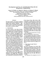
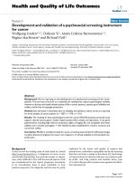
Figure 1: Nomadic XR4000 and PUMA 560
implement such a design because of the difficulty
of the control (West and Asada 1994). More re-
cently, a velocity controlled, powered caster pro-
totype robot was demonstrated (Wada and Mori
1996).
A dynamically-controlled, holono mic mobile robot
is particularly desirable in a mobile manipulation
system for many reasons. A holonomic robot
makes for easier gross motion planning and navi-
gation. It allows for full use the null space motions
of the system to improve the workspace and overall
dynamic endpoint prope rties. A dynamically con-
trolled mobile robot is especially impo rtant when
used as the base “joints” of a mobile manipula-
tion system so that the dynamic forces developed
by the manipulator can be deco upled with forces
generated in the base “joints”.
We will present the design fundamentals of a work-
ing PCV mechanism, the Nomadic Technologies
XR4000, shown in Figure 1. We will also pr e sent
the ne w framework for efficient dynamic control of
a PCV. The experimenta l results prese nted in the
paper will show the benefit of this control frame-
work and its impact on the integration of the PCV
in a full mobile manipulation system.
2
2 Design
The PCV concept provides an effective approach
for the development of holonomic mobility for a
number of reasons. The contact p oints between the
wheels and the ground move in a continuous man-
ner and thus do not induce vibrations fr om shifting
support points or discontinuous wheel velocities.
The locatio n of each contact point is well known
so tha t control is more ex act. Each wheel mecha-
nism contains a single nonholonomic wheel which
is large enough for good ground clearance. One fi-
nal point which has not been adequately addressed
previously, is that the PCV is the only holonomic
mechanism which can be designed to effectively use
currently available pneumatic tires — and conse-
quently benefit from the suspension, traction, and
wear properties of this well developed technolo gy.
Because there are no passive and more importantly
no unmeasured bodies in a powered caster design
the dynamics of the sy stem can be accurately mod-
eled.
Figure 2: Powered Caster Module
A PCV is composed of n ≥ 2 powered caster mod-
ules as illustrated in Figure 2. The modules could
vary in size and power from module to module, but
without loss of generality, we will assume that all
the modules are identical. The PCV design is de -
fined by the strictly positive geometric parameters:
wheel radius(r), caster offset(b), and w hee l module
placement(h , β) (see Figures 3 and 4). Along with
the mass and inertia of each compo nent in the de-
sign, parameters which affect the system dynamics
include the gear ratios and motor sizes . Values for
the geometric parameters must be selected so that
1
φ
2
φ
3
φ
1
h
2
h
3
h
1
β
2
β
3
β
−
Figure 3: Powered Caster Vehicle Geometry
the area swept out by each wheel does not inter-
sect any other. The wheels should have a large
enough radius to surmount anticipated obstacles.
The dynamic tradeoffs involve the geometry as well
as the motors and gea ring. Careful selection mus t
be made to result in a mechanism which has good
acceleration while ma intaining the ability to reach
the desired top speed. At the same time, by choos-
ing components so that motor and gearbox speeds
are kept low, mechanical noise due to high compo-
nent spee ds can be minimized.
The PCV mechanism shown in Figure 1, a No-
madic Technologies XR4000 mobile robot, was de-
signed to be a high perfor mance holonomic vehicle
for mobile robotics and mobile ma nipulation. It
has four 11 cm diameter wheels with 2 cm cas ter
offset. It can accelerate at 2 m/s
2
on most surfaces
and has a top speed of 1.25 m/s. The controller of
the XR4000 used herein was mo dified at Stanford
University by replacing the standard PWM motor
amplifiers with current controlled motor amplifiers.
3 Dynamic M odeling
Typically, the dy namic equations of motion for
a parallel system with nonholonomic constraints
such as a PCV are fo rmed in one of two ways:
the unconstrained dyna mics of the whole system
can be derived and the the constraints are ap-
plied to reduce the number o f degree s of freedom
(Campion, Bastin, and d’Andr´ea-Novel 1993); or
the system is cut up into pieces, the dyna mics of
3
these subsystems are found, and the loop closure
equations are used to eliminate the extra degrees
of freedom. For our four-wheeled XR40 00 robo t,
using the first method, we will obtain 11 equa-
tions for the unconstrained system and 8 constraint
equations for a total of 19 equations. The sec-
ond method will yield 12 equations for the uncon-
strained subsystems and 9 constraint equations for
a total of 21 equations. These systems of equations
mus t then be reduced to 3 equations. Ideally, both
these methods would yield the same minimal set
of dynamic equa tions, but in practice it is difficult
to reduce the proliferation of terms that are intro-
duced in a large number of equations.
h
b
r
β
θ
φ
&
ρ
&
σ
&
˙
w =
˙
φ
˙ρ
˙σ
˙
x =
˙x
˙y
˙
θ
Figure 4: Powered Caster “Manipulator”
The PCV is treated as a collection of o pen-chain
manipulators that will be combined to form the
overall mechanism model. This is accomplished
with the same concept used for multiple arms in
cooperative manipulation. The open-chain mecha-
nism is modeled, as shown in Figure 4, with steer,
˙
φ, roll, ˙σ, and twist at the wheel contact, ˙ρ, degrees
of freedom. The dynamic equations of motion for
this three DOF serial manipulator can be fo und
easily and written as (Craig 1989),
A(w)
¨
w + b(w,
˙
w) = γ (1)
where w a nd its derivatives are the wheel mod-
ule coordinate positions, velocities, and accelera-
tions, A is the symmetric mass matrix, b is the
vector of centripetal and Coriolis coupling terms,
and γ is the joint torque vector of steer, roll, and
twis t torques. We assume that the PCV is on level
ground and have dropped the effects of gravity.
Because of the parallel nature of the final mecha-
nism we choose to write the relationship between
wheel module speeds and local Cartesian speeds,
˙
x, as
˙
w = J
−1
˙
x (2)
J
−1
=
−sφ/b cφ/b h[cβcφ + sβsφ]/b − 1
cφ/r sφ/r h[cβsφ − sβc φ]/r
−sφ/b cφ/b h[cβcφ + sβsφ]/b
Fo r compactness we use s· and c· as shorthand for
sin(·) a nd cos(·). It is interesting to note that the
first two rows of J
−1
express the nonholonomic con-
straints due to ideal rolling while the third row is
a holonomic constraint: θ = σ − φ.
Using the joint space dynamics from eqn. 1 and
the inverse Jacobian in eqn. 2, we can express the
operational space dynamics of the i
th
manipulator
as
Λ
i
(w
i
)
¨
x + µ
i
(w
i
,
˙
w
i
,
˙
x) = F
i
(3)
with
Λ
i
= J
−T
i
A
i
J
−1
i
µ
i
= J
−T
i
A
i
˙
J
−1
i
˙
x + b
i
where Λ is the operational space mass matrix, µ
is the operational space vector of centripetal and
Coriolis terms, and F is the force/torque vector at
the origin of the end effector coordinate system.
Since our manipulator is s imple and not redun-
dant we compute J
−1
directly, thus avoiding an
inversion operation which is tr aditionally required.
Also note that as expressed here µ
i
is a function of
w
i
,
˙
w
i
and
˙
x. This representation allows us to use
exact local information, such as the rolling speed
of the whee l, which is measured directly and to
use the best estimates of the ba se speeds which we
develop in section 4.
Figure 5: Cooperating powered caster manipula-
tors
If we choose the end effector frames of the various
manipulators such that they are coincident while
4
the wheel modules are correctly positioned with re-
sp e c t to one another (see Figure 5), then, using the
augmented object model of Khatib (Khatib 1988),
we can write the overall operatio nal s pace dynam-
ics of the mobile base.
Λ
¨
x + µ = F (4)
with
Λ =
n
i
Λ
i
; µ =
n
i
µ
i
; F =
n
i
F
i
Here, Λ, µ, and F have the same meanings as be-
fore but now represent the properties of the entire
robot.
With this algorithm we have determined the opera-
tional space dynamic eq uations of motion directly.
Fo r our four-wheeled XR4000 robot we generate
12 equations, 3 for e ach i in eqn. 3, which are then
added in groups of four to give the required 3 op-
erational space equations. Using the symb olic dy-
namic equation ge nerator AUTOLEV to create Λ
and µ, the number of multiplies and additions are
reduced from 8180 and 2244, to 2174 and 567.
4 Dynamically Decoupled
Control
The contro l and dynamic dec oupling of the PCV is
achieved by selecting the operational space control
structure (Khatib 1987)
F = Λ F
∗
+ µ (5)
where F is the operational space force which is to
be applied to the PCV and F
∗
is the control force
for our linearized unit mass system. As an ex-
ample we can choose to implement a simple P- D
controller
F
∗
= −K
p
(x − x
d
) − K
v
(
˙
x −
˙
x
d
) +
¨
x
d
(6)
with K
p
, K
v
the position and velocity gains, and
x
d
and its derivatives the desired position, velocity
and acceleration.
This approach requires that we know the op e ra-
tional space velocities,
˙
x, of the PCV and the actu-
ated robot joint torques, Γ, necessary to produce
the commanded operational space force, F. The
XR4000 powered cas ters (see Figure 2 ) have an en-
coder on each motor. The encoders together with
knowledge of the gearbox kinematics allow us to
calculate the positions and velocities of the steer-
ing and rolling joints of each module. We can write
the relationships between the observed robot joint
sp e e ds and the operational speeds of the i
th
wheel
as the wheel constraint matrix, C
i
, which contains
the two nonholonomic constraints from “manipu-
lator” model in eqn. 2. We will use
˙
q
i
= [
˙
φ
i
˙ρ
i
]
T
to designate the observed joint speeds of the i
th
wheel.
˙
q
i
= C
i
˙
x (7)
C
i
=
−sφ
i
/b cφ
i
/b h
i
[cβ
i
cφ
i
+ sβ
i
sφ
i
]/b − 1
cφ
i
/r sφ/r h
i
[cβ
i
sφ
i
− sβ
i
cφ
i
]/r
The overall motion of the joints in the robot c an be
described by gathering the wheel constraint matri-
ces into the constraint matrix, C.
˙
q = C
˙
x (8)
˙
q =
˙
q
1
.
.
.
˙
q
n
; C =
C
1
.
.
.
C
n
The dual of this rela tio nship describes the opera-
tional space force produced by the torques at the
actuated joints.
F = C
T
Γ (9)
To find the operational space veloc ities and actu-
ated joint torques we need to find the inverse rela-
tionships to eqns. 8,9. One common approach is to
use a generalized inverse (Muir and Neuman 1986)
of the the full c onstraint matrix C. Our approach
instead involves two steps: finding the velocities at
the contact points from the joint speeds and then
resolving the contact point velocities to find the
overall vehicle speeds. This provides a more phys-
ically intuitive solution to the inverse problem.
It may be easiest to visualize the contact point
velocities as the speeds,
˙
p, that the contact points
would have in the world if the rob ot body were
held fixed and the wheels were not in contact with
the ground. This is illustrated in Figure 6.
The sensed contact points veloc ities can be cal-
culated from the measured joint speeds with the
5
1
&
2
&
n
&
Figure 6: Contact point velocities
one-to-one mapping below where C
q
is square, full
rank, block diagonal, and invertible.
˙
q = C
q
˙
p (10)
When the robot obeys the ideal rolling assump-
tions there exists a vehicle velocity where the
sensed contact speeds are identical to the consis-
tent set of contact s peeds,
˙
ˆ
p, found with the kine-
matic relationship
˙
ˆ
p = C
p
˙
x (11)
However, as is to be expected, when there is some
slippage and measurement noise,
˙
p =
˙
ˆ
p. By us-
ing the Moore-Penrose pseudo-invers e of the non-
square matrix C
p
we get
˙
x = C
+
p
˙
p which will
minimize the total perceived slip by minimizing the
differences between
˙
p and
˙
ˆ
p. Our estimate of the
robot velocity ass uming that slip is minimized uses
a generalized inver se of the constraint matrix and
is
˙
x = C
#
qp
˙
q (12)
where
C
#
qp
= C
+
p
C
−1
q
(13)
We have tested the odometry of our XR4000 mov-
ing randomly for one minute in a 1.5m x 2.5m area
and then re tur ning to its starting position. When
using the generalized inverse from eqn. 13 the dead-
reckoning er ror was less than half as large as when
the pseudo-inverse of the constr aint matr ix was
used.
The dual of this result is just as ideal. There are
many ways to distribute the e ffort among the joints
to achieve a desired operational space force . By
distributing the joint torq ues using the transpose
of the generalized inverse in eqn. 13
Γ = C
#
T
qp
F (14)
we minimize, in a least squares way, the contact
forces developed by the wheels. The consequence
is tha t the tractive effort is spread as evenly as
possible among the wheels and the tendency for
any one w hee l to loose tractio n is minimized.
Other useful, physically meaningful generalized in-
verses can be found using the same methodology as
follows. A one-to-one mapping from the velocities
of interest to the measured velocities is derived. A
second mapping, which goes from the operational
sp e e ds to the velocities of interest is derived. The
product of the two mappings must equal the con-
straint matrix, C. The new generalized inverse of
the constraint matrix is then the pseudo-inverse of
the second matrix times the dir e c t inve rse of the
first matrix.
A sec ond us eful exa mple can be develope d by map-
ping the measured and opera tio nal velocities to
the motor speeds. It generates a generalized in-
verse which, when used to distribute the opera-
tional forces among the motor s, the total motor
power is minimized. There have been problems
with using gener alized inverses of Jacobians in the
past for manipulators because the meaning of min-
imizing quantities which have a combination of lin-
ear and angular units is not well defined. The two
proposed generalized invers e s do not suffer from
this problem because the velocity vectors of inter-
est have consistent units. Only linear units are
present in the vector of contact velocities from the
first example, while the speeds of interest in the
second example have only angular units.
5 Experiments
5.1 Setup
Two experiments are prese nted. All experiments
use a Nomadic Technologies XR4000 which is a
four-wheeled, Powered Caster Vehicle. The mobile
manipulation ex periment uses a PUMA 560 which
is mounted on the XR4000 as shown in Figure 1.
The controller software was run on an on-board
450 MHz Pentium II, using the QNX real-time op-
erating system. The mobile manipulation experi-
ment was ca rried out with the addition of a fast
dynamics algorithm developed and implemented
by K.C. Chang in our lab (Chang 20 00). All ex-
6
periments were run using the controller structure
shown in Figure 7 for the PCV control, with a
1000 Hz servo rate for all calculations. All experi-
ments were run fully autonomously with the robot
using its on-board batteries for power and radio
Ethernet for communication.
x
d
x
d
x
d
x
.
.
q
q
.
x
#
C
Γ
+
+
Compensator
ROBOT
#
C
T
F F
*
Λ
µ
Figure 7: Controller Schematic
5.2 PCV Dynamic Decoupling
The first experiment demonstrates the effective-
ness of the proposed dynamically decoupled, dy-
namic control of a PCV. In this experiment, the
robot was commanded to move from its starting lo-
cation, (x, y, θ) = (0, 0, 0), to one meter in the y di-
rection, (x, y, θ) = (0, 1, 0), and then back again,
repeatedly. The robot was commanded to follow a
straight line path without rotation i.e. x = 0 and
θ = 0. The maximum acceleration magnitude was
limited to 1.0 m/s
2
. The gains used in this ex-
periment were reduced by a factor of 10 from the
ty pical gains used during norma l motions so that
dynamic disturbances would be more apparent.
0 2 4 6 8 10
0
0.2
0.4
0.6
0.8
1
time (s)
y−position (m)
actual
desired
0 2 4 6 8 10
−1
−0.5
0
0.5
1
time (s)
y−speed (m/s)
actual
desired
Figure 8: Position vs. time and velo c ity vs. time
with dynamic compensation
Figure 9: Wheel “flip” during y-axis motion which
leads to large dynamic disturbance forces
The desired position and velocity for the only
changing coordinate, y, are shown with the dashed
lines in Figure 8. Each time the XR4000 changes
direction in this task, all four wheels must flip
their orientations (see Figure 9), and in doing so,
cause large dynamic coupling forces. The good
performance, in spite of re duced gains, recorded
by the solid lines in Fig ure 8, are a res ult of com-
pens ating for the coupled dynamics of the mecha-
nism. To illustrate the importance of the role de-
coupling plays, Figure 10 shows the compensation
used for the x and θ “joints” of the PCV. Notice
that the magnitude o f the dynamic x disturbance
force reaches 600 N and the dynamic θ distur bance
torque reaches 100 N·m — significant disturbances,
even for a 160 kg robot.
7
0 2 4 6 8 10
−600
−400
−200
0
200
400
600
time (s)
force (N)
0 2 4 6 8 10
−100
−50
0
50
100
time (s)
torque (N m)
Figure 10: Dynamic compensation force-x and dy -
namic compensation torque-θ
0 2 4 6 8 10
−30
−20
−10
0
10
20
30
time (s)
x (mm)
0 2 4 6 8 10
−3
−2
−1
0
1
2
3
time (s)
theta (deg)
Figure 11: Positions without dynamic compensa-
tion
In Figures 11 and 12 some o f the disturba nce ef-
fects of the dynamic forces are shown. In Figur e 11 ,
the robot was run without using dynamic compen-
sation and has position errors on the order of 30
mm and 3
◦
. In Figure 12, the robot was run while
implementing the propo sed dynamic compensation
and the errors are reduced to about 5 mm and 0.5
◦
.
0 2 4 6 8 10
−30
−20
−10
0
10
20
30
time (s)
x (mm)
0 2 4 6 8 10
−3
−2
−1
0
1
2
3
time (s)
theta (deg)
Figure 12: Pos itio ns with dynamic comp ensation
5.3 Mobile Manipulator Coordina-
tion
The second experiment shows the effectiveness of
using operationa l space control on the mobile robot
when it is acting as the base “joints” of the mobile
manipulator robot system. In this exper iment the
PCV, which we will call the base in this context,
was commanded to travel from the original loca-
tion, (x, y, θ) = (0, 0, 0), to two meters in the y di-
rection, (x, y, θ) = (0, 2, 0 ). The PUMA 560, was
set to begin in the “home” position with joint 2
level and pointing in the y direction and joint 3
vertical, pointing upward. When the motion was
started, the PUMA was commanded to wave its
arm by moving joint 1 (waist) betwee n 0.0 and 0 .6
radians (34.4
◦
) at 0.95 Hz (6.0 r ad/sec) in a si-
nusoidal trajectory. This trajectory is shown in
Figures 13 and 14. Dynamic decoupling is used for
the motions shown in these two figures.
0 2 4 6 8 10
0
0.5
1
1.5
2
time (s)
position (m)
y−position
x−position
actual
desired
0 2 4 6 8 10
0
10
20
30
40
time (s)
angle (deg)
actual
desired
Figure 13: Base x and y positions vs. time and
PUMA joint 1 angle vs. time
The rapid waving o f the PUMA arm caused large
dynamic disturbance torques particularly to the
orientation of the base. Again, the gains used in
this experiment were reduced by a factor of 10 from
the typical gains used during normal motions so
that dynamic disturbances would be more appar-
ent. The orientation errors of the base are shown
in Figure 15. Without dynamic compensation the
orientation of the base has errors of about ±6
◦
;
while with dynamic comp e nsation for the distur-
bance forces generated by the PUMA the orienta-
tion error is reduced to less than ±1
◦
.
8
0 0.5 1 1.5 2
−0.4
−0.2
0
0.2
0.4
PCV y−axis (m)
PCV x−axis (m)
Figure 14: Path of ro bot and manipulator arm
0 2 4 6 8 10
−8
−6
−4
−2
0
2
4
6
8
time (s)
angle error (deg)
0 2 4 6 8 10
−8
−6
−4
−2
0
2
4
6
8
time (s)
angle error (deg)
Figure 1 5: Base orientation error without and with
dynamic compensation
6 Conclusions
We have presented the design of a new wheeled
holonomic mobile robot, the powered caster ve-
hicle, or PCV, which is being produced as the
XR4000 mobile robot by Nomadic Technologies.
The desig n of the powered caster vehicle provides
smooth accurate motion with the ability to tra-
verse the hazards of typical indoor envir onments .
The desig n can be used with two or more wheels,
and as implemented with four wheels provides a
stable platform for mobile manipulation.
We have also describ e d a new approach for a mod-
ular, efficient dynamic modeling of wheeled vehi-
cles. This approach is based on the augmented
object model originally developed for the study of
cooperative manipulators. The a c tua tio n redun-
dancy is resolved to effectively distribute the ac-
tuator torques to minimize internal or antagonis-
tic fo rces between wheels. This results in reduced
wheel slip and improved odometry.
Using the vehicle dynamic model and the actuation
and measurement redundancy resolution, we have
developed a control structure that allows vehicle
dynamic decoupling and slip minimization. The
effectiveness of this approach was experimentally
demonstrated for motions involving large dynamic
effects.
The PCV dynamic model and control structure
have been integrated into a new mobile manipula-
tion platform integrating the XR4000 and a PUMA
arm. The experimental results on the new platform
have shown full dynamic decoupling and improved
performance.
Acknowledgments
We gratefully acknowledge Nomadic Technologies
Inc., where the development of the powered caster
mechanism took place; for the resources devoted to
this project, and to the work of all the individuals
there, especially Anthony de l Balso, Rich Leg rand,
Jim Slater and J ohn Sla ter who were instrumental
9
in the creation of the XR4000 mobile robot. The
financial support of Boeing, and Honda is grate-
fully acknowledged. Thanks also to K.C. Chang
for development of the mobile manipulation con-
troller software in which the PCV controller was
integrated.
References
Bradbury, H. M. (1977, December). Omni-
directional transport device. U.S. Patent
#4223753.
Campion, G., G. Bastin, and B. d’Andr´ea-Novel
(1993, May). Structural properties and clas-
sification of kinematic and dynamic models
of wheeled mobile robots. In Proc. IEEE In-
ternational Conference on Robotics and Au-
tomation, Atlanta, GA, pp. 462–469.
Carlisle, B. (1983). An omni-directional mo-
bile robot. In B. Ro oks (Ed.), Developments
in Robotics, pp. 79–87. Kempston, England:
IFS Publications.
Chang, K S. (2000, Mar ch). Efficient al-
gorithms for articulated branching mecha-
nisms: dynamic modeling, control, and sim-
ulation. Ph. D. thesis, Stanford University,
Stanford, CA.
Craig, J. J. (1989). Introduction to Robotics (2nd
ed.). Menlo Park, CA: Addison- Wesley.
Hirose, S. and S. Amano (1993, October). The
VUTON: High payload high efficiency holo-
nomic omni-directional vehicle. In 6
th
Inter-
national Symposium on Robotics Research.
Ilon, B. E. (1971, December). Directionally
stable self propelled vehicle. U.S. Patent
#3746112.
Khatib, O. (1987, February). A unified approach
for motion and force control of robotic ma-
nipulators: The operational space formula-
tion. IEEE Journal of Robotics and Automa-
tion RA- 3 (1), 43–53.
Khatib, O. (1988). Object manipulation in a
multi-effector robot sy stem. In Robotics Re-
search 4 Proc. 4th Int. Symposium, Cam-
bridge: MIT Press, pp. 137–144.
Khatib, O., O. Brock, K. Yokoi, and R. Holm-
berg (1999). Dancing with juliet 1999. IEEE
Robotics and Automation Conference Video
Proceedings.
Khatib, O., K. Yokoi, O. Brock, K. Chang , and
A. Casal (1999). Robots in human environ-
ments: Basic autonomous capabilities. In-
ternational Journal of Robotics Research 18,
684–696.
Khatib, O., K. Yokoi, K. Chang, D. Ruspini,
R. Holmberg, and A. Casa l (1996). Proceed-
ings of the ieee/rsj international conference
on intelligent robots and systems. In Ve-
hicle/arm coordination and multiple mobile
manipulator decentralized cooperation, Vol-
ume 2, Osaka, Japan, pp. 546–553.
Killough, S. M. and F. Pin (1992, May). Design
of an omnidirectional and holonomic wheeled
platform prototype. In Proc. IEEE Interna-
tional Conference on Robotics and Automa-
tion, Vo lume 1, Nice, France, pp. 84–90.
La, H. T. (1979, January). Omnidir ectional ve-
hicle. U.S. Patent #4237990.
Muir, P. F. and C. P. Neuman (1986, June).
Kinematic modeling of wheeled mobile
robots. Technical Report CMU-RI-TR-86-
12, The Robotics Institute, Carnegie-Mellon
University, Pittsburgh, PA.
Pin, F. G. and S. M. Killough (1994, August).
A new family of omnidirectional and holo-
nomic wheeled platforms for mobile robots.
IEEE Transactions on Robotics and Automa-
tion 10 (4), 480–489.
Wada, M. and S. Mori (1996, April). Holo-
nomic and omnidirectional vehicle with con-
ventional tires. In Proc. IEEE International
Conference on Robotics and Automation,
Minneapolis, MN, pp. 3671–367 6.
West, M. and H. Asada (1992, May). Design of
a holonomic omnidirectional vehicle. In Proc.
IEEE International Conference on Robotics
and Automation, Nice, Fra nce , pp. 97–103.
West, M. and H. Asada (1994). Design of ball
wheel vehicles with full mobility, invariant
kinematics a nd dy namics and anti-slip con-
trol. In Proceedings of the ASME Design
Technical Conferences, 23rd Biennial Mech-
anisms Conference ASME, Volume 72, Min-
neapolis, MN, pp. 377–384.
10