A Parallel Algorithm based on Convexityfor the Computing of DelaunayTessellation
Bạn đang xem bản rút gọn của tài liệu. Xem và tải ngay bản đầy đủ của tài liệu tại đây (1.53 MB, 77 trang )
VIETNAM NATIONAL UNIVERSITY, HANOI
UNIVERSITY OF SCIENCE
FACULTY OF MATHEMATICS, MECHANICS AND INFORMATICS
———–OOO————
DONG VAN VIET
A Parallel Algorithm based on Convexity
for the Computing of Delaunay
Tessellation
Undergraduate Thesis
Advanced Undergraduate Program in Mathematics
HANOI - 2012
VIETNAM NATIONAL UNIVERSITY, HANOI
UNIVERSITY OF SCIENCE
FACULTY OF MATHEMATICS, MECHANICS AND INFORMATICS
———–OOO————
DONG VAN VIET
A Parallel Algorithm based on Convexity
for the Computing of Delaunay
Tessellation
Undergraduate Thesis
Advanced Undergraduate Program in Mathematics
Instructor: Assoc. Prof. Dr. Phan Thanh An
Institute of Mathematics
Vietnam Academy of Science and Technology
HANOI - 2012
Acknowledgements
This thesis is based on the following two papers: “A parallel algorithm based on
convexity for the computing of Delaunay tessellation” (by Phan Thanh An and Le Hong
Trang, published in Numerical Algorithms, Vol. 59, No. 3, pp. 347-357, 2012) and
“Spines for constructing convex hulls in 2D and their applications” (by Phan Thanh
An, Dong Van Viet, and Dinh Thanh Giang, in preparation, 2012). In the process
of doing this thesis, I received much important encouraging factor and support from
university, teachers, family and friends. I would like to thank those people who have
contributed significantly to this thesis.
The work on this thesis could not have been started if it were not for the generous
support and the detail guide provided by my instructor, Associate Professor Phan
Thanh An. I am indebted to his advice during time of writing this thesis. He provided
helpful feedback, support and valuable advice in writing this thesis.
This work was partially supported by the Center for High-Performance Computing.
I want to thank Associate Professor Nguyen Huu Dien, Master of Science Le Hoang
Son, and Mr Pham Duy Linh, who kindly provided a chance me to execute an parallel
program on parallel computer and supervised when the parallel program was executing.
I want to show my gratitude to all teachers from Faculty of Mathematics, Mechanics,
and Informatics, who had taught me a lot of knowledge through four years. Students at
K1 Advanced Mathematics class have been extremely helpful in providing suggestions
and constructive criticism during the preparation of the manuscript.
Outside Hanoi University of Science, there are many people who have provided me
with their insightful comments and generously shared their document and knowledge.
I would like to thank, in particular, Miss Dinh Thanh Giang for her advice.
Finally, I want to thank to my family, mostly for their understanding of the time
commitment necessary to write such a thesis. To all of them I wishes to express my
sincere gratitude.
Hanoi, October 28, 2012
Dong Van Viet
3
List of Symbols
∠ Angle
Triangle
∆ Diameter of a set of points
µ Rounding unit
θ
ab
The angle of a segment ab
θ(ab, cd) The angle of two segments ab and cd
ab The segment joining a and b
CH(P ) The convex hull of a set of points P
D A domain in E
d
D(P ) The Delaunay tessellation of a set of points P
E
d
d-dimensional Euclidean space
H A Delaunay path
L Median line
P A set of points
Q
i
A monotonic sequence
End of a proof
2D Two-dimensional space
3D Three-dimensional space
4
Contents
Acknowledgements 3
List of Symbols 4
Introduction 7
1 Convex Sets and Convex Hulls 10
1.1 Geometric Preliminaries . . . . . . . . . . . . . . . . . . . . . . . . . . 10
1.2 Convex Sets and Convex Hulls . . . . . . . . . . . . . . . . . . . . . . . 11
1.3 Algorithms for Computing Convex Hulls . . . . . . . . . . . . . . . . . 13
1.4 Graham’s Convex Hull Algorithm . . . . . . . . . . . . . . . . . . . . . 14
1.4.1 Pseudocode, Version A . . . . . . . . . . . . . . . . . . . . . . . 14
1.4.2 Pseudocode, Version B . . . . . . . . . . . . . . . . . . . . . . . 17
1.4.3 Implementation of Graham’s Convex Hull Algorithm . . . . . . 18
1.5 Spines for Constructing Convex Hulls in 2D . . . . . . . . . . . . . . . 22
1.5.1 Arithmetic Model . . . . . . . . . . . . . . . . . . . . . . . . . . 22
1.5.2 Calculating Angles . . . . . . . . . . . . . . . . . . . . . . . . . 23
1.5.3 Generating Monotonic Sequences . . . . . . . . . . . . . . . . . 25
1.5.4 Extracting a Spine . . . . . . . . . . . . . . . . . . . . . . . . . 27
2 Delaunay Triangulations 35
2.1 Delaunay Triangulations . . . . . . . . . . . . . . . . . . . . . . . . . . 35
2.1.1 Definition of Delaunay Triangulations . . . . . . . . . . . . . . . 35
2.1.2 Basic Properties of Delaunay Triangulations . . . . . . . . . . . 37
2.2 Algorithms for Computing Delaunay Triangulations . . . . . . . . . . . 41
2.3 Delaunay Triangulations and Connection to Convex Hulls . . . . . . . . 42
2.4 Delaunay Triangulations and Restricted Areas . . . . . . . . . . . . . . 46
3 A Parallel Algorithm for Computing Delaunay Triangulations 51
3.1 Parallel Algorithms . . . . . . . . . . . . . . . . . . . . . . . . . . . . . 51
3.2 Correctness and Implementation of the Parallel Algorithm . . . . . . . 54
5
3.3 Remarks . . . . . . . . . . . . . . . . . . . . . . . . . . . . . . . . . . . 55
Conclusion 57
Appendix A 58
Introduction to MPI Library . . . . . . . . . . . . . . . . . . . . . . . . . . . 58
Getting Started with MPI on the Cluster . . . . . . . . . . . . . . . . . . . . 58
Compilation . . . . . . . . . . . . . . . . . . . . . . . . . . . . . . . . . 58
Running MPI . . . . . . . . . . . . . . . . . . . . . . . . . . . . . . . . 59
The Basis of Writing MPI Programs . . . . . . . . . . . . . . . . . . . . . . 59
Initialization, Communicators, Handles, and Clean-Up . . . . . . . . . 59
MPI Indispensable Functions . . . . . . . . . . . . . . . . . . . . . . . 60
Example . . . . . . . . . . . . . . . . . . . . . . . . . . . . . . . . . . . 63
Timing Programs . . . . . . . . . . . . . . . . . . . . . . . . . . . . . . . . . 65
Debugging Methods . . . . . . . . . . . . . . . . . . . . . . . . . . . . . . . 66
Appendix B 67
C Codes for Graham’s Convex Hull Algorithm . . . . . . . . . . . . . . . . . 67
C Code for Computing Delaunay Triangulations . . . . . . . . . . . . . . . . 70
A Parallel Code for Computing Delaunay Triangulations . . . . . . . . . . . 72
Appendix C 75
Center for High Performance Computing CPHC-HUS . . . . . . . . . . . . . 75
References 76
6
Introduction
Computational geometry is a branch of computer science concerned with the design
and analysis of algorithms to solve geometric problems (such as pattern recognition,
computer graphics, operations research, computer-aided design, robotics, etc.) that
require real-time speeds. Until recently, these problems were solved using conventional
sequential computer, computers whose design more or less follows the model proposed
by John von Neumann and his team in the late 1940s (see [14]). The model consists
of a single processor capable of executing exactly one instruction of a program during
each time unit. Computers built according to this paradigm have been able to perform
at tremendous speeds. However, it seems today that this approach has been pushed
as far as it will go. For example, the speed of light imposes a limit that cannot be
surpassed by any electronic device.
On the other hand, our appetite appears to grow continually for ever more powerful
computers capable of processing large amounts of data at great speeds. One solution
to this predicament that has recently gained credibility and popularity is parallel pro-
cessing. The main purpose of parallel processing is to perform computations faster
than can be done with a single processor by using a number of processors concurrently.
A parallel computer is simply a collection of processors, typically of the same type,
interconnected in a certain fashion to allow the coordination of their activities and the
exchange of data (see [14]).
In order to solve a problem efficiently on a parallel machine, it is usually necessary
to design an algorithm that specifies multiple operations on each step, i.e., a paral-
lel algorithm. This algorithm can be executed a piece at a time on many different
processors, and then put back together at the end to get the correct result.
MPI (Message Passing Interface) is one of the most popular library for message-
passing within a parallel program. It is a standardized and portable message-passing
system designed by a group of researchers from academia and industry to function on a
wide variety of parallel computers. The standard defines the syntax and semantics of a
core of library routines useful to a wide range of users writing portable message-passing
programs in Fortran or C/C++.
In E
n
, a Delaunay tessellation (i.e. Delaunay triangulation in the plane) is an
7
important problem in many domains, including pattern recognition, terrain modeling,
and mesh generation for the solution of partial differential equations. In many of
these domains the tessellation is a bottleneck in the overall computation, making it
important to develop fast algorithms. As a result, there are many sequential algorithms
available for Delaunay tessellation, along with efficient implementations (see [17, 20]).
Among others, Aurenhammer et al.’s method based on a beautiful connection between
Delaunay tessellation and convex hull in one higher dimension (see [7, 9, 12]). Since
these sequential algorithms are time and memory intensive, parallel implementation are
important both for improved performance and to allow the solution of problems that
are too large for sequential machines. However, although several parallel algorithms
for Delaunay triangulation have been presented, practical implementations have been
slower to appear (see [8]).
For the convex hull problem in 2D and 3D, we find the convex hull boundary in
the domain formed by a rectangular (or rectangular parallelepiped). Then the domain
is restricted to a smaller domain, namely, restricted area to a simple detection rather
than a complete computation (see [2, 3]).
Recently, some problem in the area of computational geometry has focused on the
numerical issues that arise when geometric algorithms are implemented using rounded
floating point arithmetic. Unlike other types of numerical algorithms, most geometric
algorithms require that all arithmetic be performed over the field of reals or rationals,
and they behave erratically when implemented with a non-associative number system
such as rounded arithmetic. The term robust has arisen to describe algorithms whose
correctness is not spoiled by round-off error. The assumption is we do not “cheat”:
each real varible in the algorithm is replaced by a floating point variable, and each real
addition, subtraction, multiplication and division is replaced by a single corresponding
floating point operation. Clearly, robust algorithms are of great practical interest.
Section 1.5 present the first rounded arithmetic convex hull algorithm which guarantees
a convex hull output and which has error independent of the number of input points
([16]). Some our initial results about spines are also presented in this section.
In this thesis, we present a parallel algorithm introduced by P.T. An [5] based
on divide-and-conquer strategy (see [14]). At each process of parallel algorithm, the
Aurenhammer et al.’s method (the lift-up to the paraboloid of revolution) is used. The
convexity in the plane as a crucial factor of efficience of the new parallel algorithm over
corresponding sequential algorithm is shown. In particular, a restricted area obtained
from a paraboloid given in [8] is used to discard non-Delaunay edges (Proposition 2.2).
Some advantages of the parallel algorithm are shown. Its implementation in plane is
executed easily on both PC clusters and parallel computers (Section 3.2). Compare
8
with a previous work, the resulting implementation (done at the Center for High-
Performance Computing, Hanoi University of Science [10]) significantly achieves better
speedups over corresponding sequential code given in [18] (see Table 3.1).
This thesis has three chapters and three appendices:
Chapter 1: Convex Sets and Convex Hulls. We deal with basis geometric pre-
liminaries, convex set and convex hull notions. This chapter shows some algo-
rithms for computing convex hull and goes in detail for only Graham’s convex
hull algorithm. Li and Milenkovic’s concept of spines for a point set is presented.
We present some initial results about the use of spines for constructing convex
hulls in 2D.
Chapter 2: Delaunay Triangulations. Chapter 2 majors on the definition of De-
launay triangulation and properties of Delaunay triangulation. Then it deals with
some algorithms for computing Delaunay triangulation. This chapter also shows a
beautiful connection between Delaunay tessellation and convex hulls in one higher
dimension. The so-called restricted area is presented.
Chapter 3: A Parallel Algorithm for Computing Delaunay Triangulations.
This chapter comes into contact with parallel algorithms. The algorithms are exe-
cuted on parallel computer and the results shows that the parallel algorithms run
much faster.
Appendices: These appendices are designed to give a brief overview of some of the
basis and important routines of MPI Library. Some C codes are represented here.
These appendices also include some information about the IBM System Cluster
1350 of the Center for High-Performance Computing, Hanoi University of Science,
which was used to execute the algorithms.
Some new initial results about the use of spines for constructing convex hulls in 2D
were presented at the seminar of the Department of Numerical Analysis and Scientific
Computing, Institute of Mathematics, Hanoi on October 10, 2012.
9
Chapter 1
Convex Sets and Convex Hulls
The most ubiquitous structure in computational geometry is the convex hull. It is
useful in its own right and useful as a tool for constructing other structures in a wide
variety of circumstances. The construction of the convex hull, in two dimensions, is
the subject of this chapter. For the reader’s convenience, this chapter presents some
basic geometrical notions that will be commonly used in this text.
1.1 Geometric Preliminaries
The objects considered in Computational Geometry are normally sets of points in
Euclidean space. A coordinate system of reference is assumed, so that each point is
represented as a vector of cartesian coordinates of the appropriate dimension. The
geometric objects do not necessarily consist of finite sets of points, but must comply
with the convention to be finitely specifiable. So we shall consider, besides individual
points, the straight line containing two given points, the straight line segment defined
by its two extreme points, the plane containing three given points, the polygon defined
by an (ordered) sequence of points, etc.
This section has no pretence of providing formal definitions of the geometric concepts
used in this paper; it has just the objectives of refreshing notions that are certainly
known to the reader and of introducing the adopted notation (see [20], pp.17-19).
A Cartesian coordinate system specifies each point uniquely in a plane by a pair
of numerical coordinates, which are the signed distances from the point to two fixed
perpendicular directed lines, measured in the same unit of length. Each reference line
is called a coordinate axis or just axis of the system, and the point where they meet is
their origin, usually at ordered pair (0, 0).
By E
d
we denote the d−dimensional Euclidean space, i.e., the space of the d-tuples
(x
1
, . . . , x
d
) of real numbers x
i
, i = 1, . . . , d with metric (
d
i=1
x
2
i
)
1/2
. We shall now
review the definition of the principal objects considered by Computational Geometry.
Point: A d-tuple (x
1
, . . . , x
d
) denotes a point p of E
d
; this point may be also
10
interpreted as a d-component vector applied to the origin of E
d
, whose free terminus
is the point p.
Line: Given two distinct points q
1
and q
2
in E
d
, the linear combination
αq
1
+ (1 − α)q
2
(α ∈ R)
is a line in E
d
.
Polygon: In E
2
a polygon is defined by a finite set of segments such that every
segment extreme is shared be exactly two edges and no subset of edges has the same
property. The segments are the edges and their extremes are the vertices of the polygon.
A polygon is simple if there is no pair of nonconsecutive edges sharing a point.
Polyhedron: In E
3
a polyhedron is defined by a finite set of plane polygons such
that every edge of a polygon is shared be exactly one other polygon (adjacent polygons)
and no subset of polygons has the same property. The vertices and the edges of the
polygons are the vertices and the edges of the polyhedron; the polygons are the facets
of the polyhedron. A polyhedron is simple if there is no pair of nonadjacent facets
sharing a point.
Faces: The boundary of a polyhedron in E
3
consists of polygons, which are called
faces. Generally, we shall refer to a bounded d-dimensional polyhedral set as a convex
d-polytope. The boundary of a polytope in E
d
consists of polyhedrons in E
d−1
, which
are called (d − 1)-faces; the boundary of an (d − 1)-faces consists on polyhedrons in
E
d−2
, which are called (d − 2)-faces; and so on. Note that 0-faces are vertices, and
1-faces are edges, and that (d − 1)-faces are sometimes called facets.
1.2 Convex Sets and Convex Hulls
Definition 1.1. (see [17], p.18) Given two distinct points q
1
and q
2
in E
d
, the linear
combination
αq
1
+ (1 − α)q
2
(α ∈ R, 0 α 1)
is called the convex combination of q
1
and q
2
.
This convex combination describes the line segment joining the two points q
1
and
q
2
. Normally this segment is denoted as
q
1
q
2
(unordered pair).
Definition 1.2. (see [17], p.18) A domain D in E
d
is convex if, for any two points q
1
and q
2
in D, the segment q
1
q
2
is entirely contained in D.
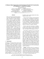
Observing Fig.1.1(a), we readily understand that the line segment between any two
points in a convex domain is included in the domain. It should be clear from Fig.1.1(b)
that any region with a “dent” is not convex, since two points straddling the dents can
11
Figure 1.1 a) Convex set, b) nonconvex set.
be found such that the segment they determine contains points exterior to the region.
A simple polygon P is convex if its interiour is a convex set. A simple polyhedron is
convex if its interior is a convex set.
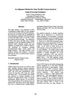
Definition 1.3. (see [17], p.21) The convex hull of a set of points P in E
d
is the
boundary of the smallest convex domain in E
d
containing P (see Fig.1.2).
Figure 1.2 Convex hull of finite set.
In the mathematics literature, the convex hull of a set of points P is denoted by
CH(P ). Note that the convex hull of a set is a closed “solid” region, including all the
points inside. Often the term is used more loosely in computational geometry to mean
the boundary of this region, since it is the boundary we compute, and that implies the
region. We will use the phrase “on the hull” to mean “on the boundary of the convex
hull.”
Theorem 1.1. (see [17], p.97) The convex hull of a finite set of points in E
d
is a
convex polytope; conversely, a convex polytope is the convex hull of a finite of points.
Convex hull problem. Given a set P of n points in E
d
, construct its convex hull
(that is, the complete description of the boundary CH(P )).
Referring to the nonconstructive nature of Definition 1.3, we must now find math-
ematical results that will lead to efficient algorithms.
12
Definition 1.4. (see [17], p.104) A point p of a convex set P is an extreme point if no
two points a, b ∈ S such that p lies on the open line segment ab.
The set E of extreme points of P is the smallest subset of P having the property
that CH(E) = CH(P ), and E is precisely the set of vertices of CH(P ). It follows that
two steps are required to find the convex hull of a finite set:
i. Identify the extreme points.
ii. Order these points so that they form a convex polygon.
The extreme points of a set P of points in the plane are the vertices of the convex
hull at which the interior angle is strictly convex, less than π. An edge is extreme if
every point of P is on or to one side of the line determined by the edge. It seems easiest
to detect this by treating the edge as directed, and specifing one of the two possible
directions as determining the “side”. Let the left side of a directed edge be the inside.
Phrased negatively, a directed edge is not extreme if there is some point that is not
left of it or on it.
The remainder of this chapter will concentrate on algorithms for constructing the
boundary of the convex hull of a finite set of points in two dimensions. We just
mention some rather inefficient algorithms and go on full detail for Graham’s convex
hull algorithm.
1.3 Algorithms for Computing Convex Hulls
In computational geometry, numerous algorithms are proposed for computing the
convex hull for a finite set of points and for other geometric objects with various
computational complexities (see [18], pp.68-91). Known convex hull algorithms are
listed below, time complexity of each algorithm is stated in terms of inputs points n
and the number of points on the hull h.
Gift wrapping algorithm: One of the simplest planar algorithm. Discovered
independently by Chand and Kapur in 1970 and by Jarvis in 1973. The idea is to use
one extreme edge as an anchor for finding the next. This works because we know that
the extreme edges are linked into a convex polygon. It has O(nh) time complexity,
where n is the number of points in the set, and h is the number of points in the hull.
In worst case the complexity is O(n
2
).
Graham’s convex hull algorithm: A slightly more sophisticated, but much more
efficient algorithm, published by Graham in 1972 with a worst-case optimal O(n log n)
algorithm. If the points are already sorted by one of the coordinates or by the angle
to a fixed vector, then the algorithm takes O(n) time. We’ll go in full detail for this
algorithm in the next section.
13
Quick hull: Discovered independently by several researchers in the late 1970s.
It was dubbed the “quick hull” algorithm by Preparata and Shamos because of its
similarity to the QuickSort algorithm (see [23], pp. 97-122). The basic intuition is as
simple as it is sound: for “most” sets of points, it is easy to discard many point as
definitely interior to the hull, and then concentrate on those closet to the hull boundary.
Just like the QuickSort algorithm, it has the expected complexity of O(n log n), but
may degenerate to O(n
2
) in the worst case.
Divide and conquer: “Divide and conquer” is a general paradigm for solving
problems that has proved very effective in computer science. The divide and conquer
technique was frist applied to the convex hull problem by Preparata and Hong (1977),
whose goal was to create an efficient algorithm for three dimensions. This techniques
achieves the same asymptotically optimal O(n log n) time complexity. It is therefore
well worth studying, even though in two dimensions it is relatively complicated.
Incremental Algorithm: Published in 1984 by Kallay. Having arrived at an
optimal O(n log n) algorithm, it may seem there is no point in exploring additional
algorithms. But there is motivation: extension to three (and higher) dimensions. Its
basic plan is simple: add the points one at a time, at each step constructing the hull
of the first k points and using that hull to incorporate the next points. It turns out
that “factoring” the problem this way simplifies it greatly, in that we only have to deal
with one very special case: adding a single point to an existing hull.
1.4 Graham’s Convex Hull Algorithm
Perhaps the honor of the first paper published in the field of computational geometry
should be accorded to Graham’s convex hull algorithm for finding the hull of points in
two dimensions in O(n log n) time. In the late 1960s an application at Bell Laboratories
required the hull of n ≈ 10, 000 points, and they found the O(n
2
) algorithm in use too
slow. Graham developed his simple algorithm in response to this need.
1.4.1 Pseudocode, Version A
The basic idea of Graham’s convex hull algorithm is simple. We will first make
several assumption that will be removed later. Assume we are given a point x interior
to the hull, and further assume that no three points if the given set (including x) are
collinear. Now sort the points by angle, counterclockwise about x. The points are now
processed in their sorted order, and the hull grown incrementally around the set. At
any step, the hull will be correct for the points examined so far, but of course points
encountered later will cause earlier decisions to be reevaluated.
14
Before proceeding to a more careful presentation, we summarize the rough algorithm
in pseudocode in Algorithm 1 ( see [18], p.74). We use stack data structure to maintain
the points of the convex hull. We assume stack primitives Push(p, S) and P op(S),
which push p onto the top of the stack S, and pop the top off, respectively (see [23],
p.233). We use t to index the stack top and i for angularly sorted points. Many
issues remain to be examined (start and termination in particular), but at this coarse
level, it should be apparent that the while loop iterates O(n) times: each stack pop
permanently removes one point, so the number of backups cannot exceed n. Together
with n forward steps, the loop iterates at most 2n times. So the algorithm runs in
linear time after the sorting step, which takes O(n log n) time.
Algorithm 1 (Graham scan, version A)
Given: P = {q
0
, q
1
, . . . , q
n
}.
Find: The convex hull of P .
1: Find interior point x; label it p
0
.
2: Sort all other points angularly about x; label p
1
, . . . , p
n−1
.
3: Stack S = {p
2
, p
1
} = {p
t
, p
t−1
, . . . , p
1
}; t indexes top.
4: i ← 3
5: while i < n do
6: if p
i
is left of (p
t−1
, p
t
) then
7: Push(p
i
, S) and set i ← i + 1
8: else
9: Pop(S)
Start and Stop of Loop
Even a simple loop can be difficult to start and stop properly: the algorithm so far
presented might have trouble at either end. The termination difficulties would arise if
a, the stack bottom, were not on the hull. Startup difficulties occur when b, the second
point pushed on stack, is not on the hull. For suppose that (a, b, c) is a right turn.
Then b would be popped from the stack, and the stack reduced to S = (a). But at
least two points are needed to determine if a third forms a left turn with the stack top.
Clearly both startup and stopping problems are avoided if both a and b are on the
hull. How this can be arranged will be shown in the next subsection.
Sorting Origin
A simplification is to sort with respect to a point of the set, and in particular, with
respect to a point on the hull. We shall use the lowest point, which is clearly on the
hull. In case there are several with the same minimum y coordinate, we will use the
rightmost of the lowest as the sorting origin. This is point 0 in Fig.1.3. Now the
sorting appears as in Fig.1.3. Note all points in the figure have been relabeled with
15
numbers; this is how they will be indexed in the implementation. We will call the
points p
0
, p
1
, . . . , p
n−1
, with p
0
the sorting origin and p
n−1
the most counterclockwise
point.
Figure 1.3 Sorting points.
Now we are prepared to solve the startup and termination problems discussed above.
If we sort points with respect to their counterclockwise angle from the horizontal ray
emanating from our sorting origin p
0
, then p
1
must be on the hull, as it forms an
extreme angle with p
0
. However, it may not be an extreme points, an issue we shall
address below. If we initialize the stack to S = {p
0
, p
1
}, the stack will always contain
at least two points, avoiding startup difficulties, and will never be consumed when the
chain wraps around to p
0
again, avoiding termination difficulties.
Collinearities
The final “boundary condition” we consider is the possibility that three or more
points are collinear, until now a situation conveniently assumed not to occur. This
issue affects several aspects of the algorithm. First we focus on defining precisely what
we seek as output.
Hull Collinearities. We insist here on the most useful output: the extreme vertices
only, ordered around the hull. Thus if the input consists of the corners of a square,
together with points sprinkled around its boundary, the output should consist of just
the four corners of the square. Avoiding non-extreme hull points is easily achieved by
requiring a strict left turn (p
t−1
, p
t
, p
i
) to push p
i
onto the stack, where p
t
and p
t−1
are the top two points on the stack. Then if p
t
is collinear with p
t−1
and p
i
, it will be
deleted.
Sorting Collinearities. Collinearities raise another issue: how should we break ties
16
in the angular sorting if both points a and b form the same angle with p
0
? One’s first
inclination is to assume (or hope) it does not matter, but alas the situation is more
delicate. There are at least two points. First, use a consistent sorting rule, and then
ensure start and stop and hull collinearities are managed appropriately. A reasonable
rule is that if angle(a) < angle(b), then a < b, if angle(a) = angle(b), then define
a < b if |a − p
0
| < |b − p
0
|, where angle(p
i
) is the counterclockwise angle between
p
0
p
i
and the positive x axis (since, p
0
is lowest, all these angles are in range (0, π] ).
Closer points are treated as earlier in the sorting sequence. With this rule we obtain
the sorting indicated by the indices in the example shown in Fig.1.4
Figure 1.4 Sorting points with collinearities.
Note, however, that p
1
is not extreme in the figure, which makes starting with
S = {p
1
, p
0
} problematic. Although this can be circumvented by starting instead with
S = {p
n−1
, p
0
} (note that p
n−1
= p
18
is extreme), we choose here a second option. It
is based on this simple observation: if angle(a) = angle(b) and a < b according to the
above sorting rule, then a is not an extreme point of the hull and may therefore be
deleted. In Fig.1.4, points p
1
, p
5
, p
9
, p
12
, and p
17
may be deleted for this reason.
Coincident Points. Often code that works on distinct points crashes for sets that
may include multiple copies of the same point. We will see that we can treat this issue
as a special case of a sorting collinearity, deleting all but one copy of each point.
1.4.2 Pseudocode, Version B
Before proceeding with implementation details, we summarize the preceding discus-
sion with pseudocode in Algorithm 2 that incorporates the changes (see [18], p.77).
We have not discussed yet the details of loop termination. Is the condition i < n
correct, even when there are collinearities? Or should it be i n, or i < n − 1?
17
Algorithm 2 (Graham scan, version B)
Given: P = {q
0
, q
1
, . . . , q
n
}.
Find: The convex hull of P .
1: Find rightmost lowest point; label it p
0
.
2: Sort all other points angularly about p
0
.
In case of tie, delete the point closer to p
0
(or all but one copy for multiple points).
3: Stack S = {p
1
, p
0
} = {p
t
, p
t−1
, . . . , p
0
}; t indexes top.
4: i = 2
5: while i < n do
6: if p
i
is strictly left of p
t−1
p
t
7: then Push(p
i
, S) and set i ← i + 1
8: else Pop(S)
Note from the pseudocode that by the time the while loop is entered, the sorting
collinearities have been removed. So once p
n−1
is pushed on the stack, we are assured
of being finished. Thus the loop stopping condition is indeed i < n.
1.4.3 Implementation of Graham’s Convex Hull Algorithm
We now describe an implementation of Algorithm 2. We assume the input points are
given with integer coordinate, and we insist upon avoiding all floating-point calculations
so that a correct output can be guaranteed. We start with data structures, then tackle
the sorting step, and finally present the code.
Data Representation
We have a choice between storing the points in an array or a list. We choose in this
instance to use an array, anticipating using a sorting routine that expects its data in a
contiguous section of memory. Each point will be represented by a structure paralleling
that used for vertices (see Appendix B, Code 1.1). The point are stored in a global
array P , with P := {P [0], . . . , P [n − 1]} corresponding to {p
0
, . . . , p
n−1
}. Each P [i] is
a structure with fields for its coordinates, a unique identifying number, and a flag to
mark deletion (see Appendix B, Code 1.2).
The stack is most naturally represented by s singly linked list of cells, each of which
“contains” a point (i.e., contains a pointer to a point record) (see Appendix B, Code
1.3). With these definitions, the stack top can be declared as tStack top, and the
element under the top is top → next.
We need three stack manipulation routines: Pop, Push, and PrintStack (see Ap-
pendix B, Code 1.4). The stack top is always the head (leftmost) element of the list.
Pop frees the top cell and returns a pointer to the next cell. Push(p,t) allocates new
storage, fills it up with p, and makes it the new stack top. Note in PrintStack that t
18
→ p → v reaches the coordinates of the point: t is type tStack, p is type tPoint, v is
type tPointi.
Sorting
FindLowest. We first dispense with the easiest aspect of the sorting step: finding
the rightmost lowest point in the set. The function Findlowest accomplishes this and
swaps the point into P [0] (see Appendix B, Code 1.5).
Avoiding Floats. The sorting step seems straightforward, but there are hidden
pitfalls if we want to guarantee an accurate sort. First we introduce a bit of notation.
Let r
i
= p
i
− p
0
, the vector from p
0
to p
i
. Our goal is to give a precise calculation to
determine when p
i
< p
j
, where “ < ” represents the sorting relation. The obvious choice
is to define p
i
< p
j
if angle(r
i
) < angle(r
j
), where angle(r) is the counterclockwise angle
of r from the positive x axis. Since p
0
is lowest, all these angles are in the range (0, π],
which is convenient because sorting positive and negative angles can tricky. C provides
precisely the desired function: angle(r) = atan2(r[x], r[y]). There are at least two
reasons not to use this. First, although the conversion from ints to doubles (required
by atan2) should be accurate, there is no guarantee that the arctangent computation
is itself accurate. Second, the arctangent is a complicated, function - left is simpler
and serves the same purpose.
Left. The function to determine whether a point is left of a line determined by two
other points, is precisely what we need to compare r
i
and r
j
. Left was itself a simple
test on the value of Area2, which computes the signed area of the triangle determined
by three points. We will use this area function rather than Left, as it is then easier to
distinguish ties. We will first discuss the overall sorting method before showing how
Area2 is employed for comparisons.
Qsort. The standard C library includes a sorting routine qsort that is at least as
good as most programmers could develop on their own, and it makes sense to use it.
Because it is general, however, it takes a bit of effort to set it up properly. The routine
requires information on the shape and location of the data and a comparison function
to compare keys. It then uses the provided comparison function to sort the data in
place, from smallest to largest. Its four arguments are:
1. A pointer to the base of the data, in our case &P[1], the address of the first point.
( Remember that P[0] is fixed as our lexicographic minimum.)
2. The number of elements to be sorted: n − 1.
3. The width of a element in bytes: sizeof(tsPoint).
4. The name of the two-argument comparison routine: Compare.
19
Compare. The routine qsort expects the comparison function to “return an integer
less than, equal to, or greater than 0 according as the first argument is to be considered
less than, equal to, or greater than the second.” Moreover, it will be called “with two
arguments which are pointers to the elements being compared”. This latter requirement
presents a slight technical problem, because we need three inputs: p
0
, p
i
, and p
j
. Here
we choose a solution: make P global, so that p
0
can be referenced inside the body of
compare without passing it as a parameter.
Finally we can specify the heart of compare: if p
j
is left of the directed line though
p
0
p
i
, then p
i
< p
j
. In other word, p
i
< p
j
if Area2(p
0
, p
i
, p
j
) > 0, in which case qsort
expects a return of −1 to indicate “less than”.
When the area is zero , we fall into a sorting collinearities, which requires action as
discussed previously (Subsection 1.4.1). First we need to decide which point is closer
to p
0
. We can avoid computing the distance by noting that if p
i
is closer, then r
i
=
p
i
− p
0
projects to a shorter length than does r
j
= p
j
− p
0
. The code computes these
projections x and y and bases further decisions on them. If p
i
is closer, mark it for
later deletion; if p
j
is closer, mark it instead. If x = y = 0, then p
i
= p
j
and we mark
the one with lower index for later deletion. In all cases, one member of {−1, 0, +1} is
returned according to the angular sorting rule detail earlier.
Main
Having worked out the sorting details, let us move to the top level and discuss main
(see Appendix B, Code 1.6). The points are read in, the rightmost lowest is swapped
with P [0] in Findlowest, and P [1], . . . , P [n − 1] are sorted by angle with qsort. The
repeated call to Compare mark a number of points for deletion by setting the Boolean
delete field. The next task is to delete those points, which we accomplish with a
simple routine Squash (see Appendix B, Code 1.7). This maintains two indices i and
j into the points array P , copying P [i] on top of P [j] for all undeleted points i. After
this the most problematic cases are gone, and we can proceed with the Graham scan,
with the call top = Graham().
Code for the Graham Scan
The code for the Graham scan is a nearly direct translation of the while loop in the
pseudocode presented earlier (Algorithm 2); see Appendix B, Code 1.8. We have the
all too common situation where the majority of the coding effort is on the periphery,
with relatively little needed for the heart of the geometric algorithm. For completed
C code for pseudocode Graham Scan Version B, see [19]. The author of this C code is
O’Rourke.
20
Complexity
We summarize in a theorem.
Theorem 1.2. (see [18], p.86) The convex hull of n points in the plane can be found
by Graham’s convex hull algorithm in O(n log n) time: O(n log n) for sorting and no
more than 2n iterations for the scan.
The complexity of the first step, finding the rightmost lowest point, is in O(n). The
sorting step use quicksort algorithm to sort points then the complexity of the sorting
step is in O(n log n) (see [23], p.84). Graham’s scan takes time proportional to the
number of vertices. Let’s see how.
In each iteration of loop, if the turn is left we change the cost of the test to the vertex
that is added to the tentative list of extreme vertices; if the turn is right we charge
the cost to the vertex that gets deleted. A vertex that is deleted right away (that is,
without being added to the tentative list of vertices) initiates a backtrack. Each step
in the backtrack, except the last, results in a deletion which we charge to the deleted
vertex. The cost of the last step is charged to the deleted vertex that initiated the
backtrack, which is thus charged twice. Se every vertex is charged at most twice. Thus
the complexity of Graham’s scan is in O(n); and that of the algorithm is in O(n log n).
Example
Figure 1.5 Graham scan for Fig.1.4
The example in Fig.1.5 (a repeat of the points in Fig.1.4) was designed to be a
stringent test of the code for Graham’s convex hull algorithm in the previous section,
as it includes collinearities of all types. The points after angular sorting, with marks
for those to be deleted, are shown in Table 1.1. (The vnums indices shown accord with
the labels in Fig.1.5) After deleting five points in Squash, n = 14 points remain.
21
Index (x, y) delete Index (x, y) delete
15 (3, -2) 7 (-3, 4)
13 (5, 1) x 4 (-2, 2)
18 (7, 4) 17 (0, 0) x
6 (6, 5) 5 (-3, 2)
12 (4, 2) 8 (-5, 2)
0 (3, 3) x 14 (-5, 1)
1 (3, 5) 9 (-5, -1)
3 (2, 5) 10 (1, -2) x
16 (0, 5) 11 (-3, -2)
2 (0, 1) x
Table 1.1 Points in Fig.1.5 after sorting.
The stack is initialized to {p
18
, p
15
}. Point p
6
and p
12
are added to form {p
12
, p
6
, p
18
, p
15
}, but then p
1
causes p
12
to be deleted. After p
1
is pushed onto the stack, p
3
causes
p
1
to be popped, because (p
6
, p
1
, p
3
) is not a strict left turn (the three points are
collinear). Then p
3
is removed by p
16
. And so on. For this example, the total number
of iterations is 19 < 2.n = 28. The final result is {p
1
, p
9
, p
8
, p
7
, p
16
, p
6
, p
18
, p
15
}, the
extreme points in clockwise order.
1.5 Spines for Constructing Convex Hulls in 2D
1.5.1 Arithmetic Model
There are three types of representation for the vertex coordinates of the input: fixed
points, single precision floating point, and double precision floating point. Fixed point
representation is essentially integer representation with the implicit understanding that
each number is multipled by some fixed power of two. Floating point representation
contain an explicit exponent field as well as mantissa. The value represented by a
floating point number with mantissa m and exponent e is 2
e
m.
The fixed or integer representation has B
I
bits; the single precision floating point
mantissa has B
S
bits; and the double has a B
D
of mantissa. For a typical computers
B
I
is 16 or 32, B
S
is 23 and B
D
is 53.
Mathematically, the consequence of single precision having B
S
bits is that every
single precision operation has a relative error bound of 2
−B
S
. For example,
|(a +
B
S
b) − (a + b)| 2
−B
S
|a + b|,
where a +
B
S
b refers to the sum of a and b computed using single precision arithmetic.
The analogous bound holds for the other three operations. This broad assumption
22
holds for all floating point representations. Particular floating point representations
may have more specific properties, but we do not expoint them here.
For a given set of points in two dimensions, the diameter ∆ of the set is defined
as usual: the maximum distance between a pair of points in the set. For geometric
calculations on a set of points, absolute error is measured as a multiple of the rounding
unit µ = 2
−B
S
∆. This multiple is independent of precision and scale.
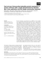
1.5.2 Calculating Angles
An essential calculation in constructing convex hull is to determine if two line seg-
ments p
1
p
2
and p
2
p
3
form a convex or concave angle. The robust convex hull algorithm
requires the slightly more general operation of computing the angle formed by separate
line segments p
1
p
2
and p
3
p
4
(see Fig 1.6). Without loss of generality, from now on
we make the assumption that the two segments have positive slope and “point to the
right”: x
p
1
< x
p
2
, y
p
1
< y
p
2
, x
p
3
< x
p
4
, and y
p
3
< y
p
4
. Define θ
p
1
p
2
to be the angle that
line p
1
p
2
makes with the x-axis. Define θ(p
1
p
2
, p
3
p
4
) = θ
p
3
p
4
−θ
p
1
p
2
to be the angle that
line p
3
p
4
makes with line p
1
p
2
. The following exact arithmetic function determines if
θ(p
1
p
2
, p
3
p
4
) is greater than or equal to zero.
PositiveAngleSign (p
1
p
2
, p
3
p
4
)
if [(x
p
2
− x
p
1
)(y
p
4
− y
p
3
) − (y
p
2
− y
p
1
)(x
p
4
− x
p
3
) 0]
then return true
else return false
Figure 1.6 Angle of 2 segments.
Actually calculating the angle θ(p
1
p
2
, p
3
p
4
) requires taking a square root and arcsine.
However, we can avoid these by computing the relative change in slope,
23
τ(p
1
p
2
, p
3
p
4
) =
tan θ(p
3
p
4
) − tan θ(p
1
p
2
)
| tan θ(p
3
p
4
)| + | tan θ(p
1
p
2
)|
=
y
p
4
− y
p
3
x
p
4
− x
p
3
−
y
p
2
− y
p
1
x
p
2
− x
p
1
|
y
p
4
− y
p
3
x
p
4
− x
p
3
| + |
y
p
2
− y
p
1
x
p
2
− x
p
1
|
=
(x
p
2
− x
p
1
)(y
p
4
− y
p
3
) − (y
p
2
− y
p
1
)(x
p
4
− x
p
3
)
|(x
p
2
− x
p
1
)(y
p
4
− y
p
3
)| + |(y
p
2
− y
p
1
)(x
p
4
− x
p
3
)|
Under the assumption that all segments have positive slope, we can leave out the
absolute values. We can compute the relative change in slope using the third formula,
or if we wish to avoid any divisions, the following function determines if the relative
change in slope is greater than a particular value κ.
RelativeSlopeCompare (p
1
p
2
, p
3
p
4
, κ)
if [(x
p
2
− x
p
1
)(y
p
4
− y
p
3
) − (y
p
2
− y
p
1
)(x
p
4
− x
p
3
)
> κ ((x
p
2
− x
p
1
)(y
p
4
− y
p
3
) + (y
p
2
− y
p
1
)(x
p
4
− x
p
3
))]
then return true
else return false
Exact convex hull algorithm use PositiveAngleSign, and the robust algorithms pre-
sented here use RelativeSlopeCompare.
Lemma 1.1. ([16]) RelativeSlopeCompare can be computed approximately using 6
single precision floating point additions and 3 single precision floating point multipli-
cations. The absolute accuracy is (3 + 6κ) ·2
−B
S
. In particular,
i. if RelativeSlopeCompare(p
1
p
2
, p
3
p
4
, κ) = true then τ(p
1
p
2
, p
3
p
4
) κ−(3 +6κ)·
2
−B
S
;
ii. if RelativeSlopeCompare (p
1
p
2
, p
3
p
4
, κ) = false then τ(p
1
p
2
, p
3
p
4
) < κ + (3 +
6κ) · 2
−B
S
.
In practice, we only invoke RelativeSlopeCompare for small values of κ (about 32 ·
2
−B
S
). In this case, we can neglect the error term 6 · 2
−B
S
. For this reason, in the rest
of the paper, the error bound will be simply 3 · 2
−B
S
.
Proof. (Lemma 1.1) A relative error of 2
−B
S
in the calculation of x
p
2
− x
p
1
results in
an absolute error of 2
−B
S
(x
p
2
− x
p
1
)(y
p
4
− y
p
3
) in the calculation of the expression,
(x
p
2
− x
p
1
)(y
p
4
− y
p
3
) − (y
p
2
− y
p
1
)(x
p
4
− x
p
3
).
Similar bounds hold for the two multiplications and three of the other subtractions.
The sum of these error is bounded by,
3 · 2
−B
S
((x
p
2
− x
p
1
)(y
p
4
− y
p
3
) + (y
p
2
− y
p
1
)(x
p
4
− x
p
3
)).
24
The final subtraction evaluated results in an absolute error bounded by,
2
−B
S
|(x
p
2
− x
p
1
)(y
p
4
− y
p
3
) − (y
p
2
− y
p
1
)(x
p
4
− x
p
3
)|.
This corresponds to a relative error of up to 2
−B
S
in the calculation of the angle.
Since this error is relative, we can treat it as if it occurs to the right hand side of
the inequality. Using similarly reasoning, it can be shown that the absolute error in
computing the expression,
κ((x
p
2
− x
p
1
)(y
p
4
− y
p
3
) + (y
p
2
− y
p
1
)(x
p
4
− x
p
3
)),
is bounded by,
5 · 2
−B
S
((x
p
2
− x
p
1
)(y
p
4
− y
p
3
) + (y
p
2
− y
p
1
)(x
p
4
− x
p
3
)),
(one extra multiplication). The transfer error from the right to the left changes 5 to 6.
Together these error bounds imply the lemma.
In the rest of this representation, we will treat τ(p
1
p
2
, p
3
p
4
) as if it were θ(p
1
p
2
, p
3
p
4
),
the actual angle between segments p
1
p
2
and p
3
p
4
. We can do this for two reasons. First,
τ(p
1
p
2
, p
3
p
4
) is always an overestimation of θ(p
1
p
2
, p
3
p
4
). In particular,
τ(p
1
p
2
, p
3
p
4
) θ(p
1
p
2
, p
3
p
4
),
for all positively sloped line segments that “point to the right.” For p
1
p
2
and p
3
p
4
nearly
horizontal or vertical, τ(p
1
p
2
, p
3
p
4
) is much larger than θ(p
1
p
2
, p
3
p
4
). This means that
an absolute error of 3 · 2
−B
S
in the measurement of τ corresponds to a much smaller
error in the measurement of θ.
The second reason that we can replace θ by τ is that for fixed p
1
p
2
, τ(p
1
p
2
, p
3
p
4
) is
a monotonic function of θ(p
1
p
2
, p
3
p
4
). This implies the following lemma which we use
in Section 1.5.4.
Lemma 1.2. ([16]) If τ(p
1
p
2
, p
2
p
3
), τ (p
1
p
2
, p
3
p
4
) < κ, then τ(p
1
p
2
, p
2
p
4
) < κ.
Proof. This simply follows from the monotonicity of τ and the fact that,
min(θ(p
2
p
3
), θ(p
3
p
4
)) θ(p
2
p
4
) max(θ(p
2
p
3
), θ(p
3
p
4
))
1.5.3 Generating Monotonic Sequences
The rest of this subsection will show how to modify the standard Graham algorithm
to generate a convex 36µ-hull of a set of n points in O(n log n) time. Let P be a set of
25