design and analysis of high-frequency matrix converters for induction heating
Bạn đang xem bản rút gọn của tài liệu. Xem và tải ngay bản đầy đủ của tài liệu tại đây (2.08 MB, 268 trang )
Nam Nguyen-Quang High-frequency matrix converters for induction heating
i
Summary
This thesis describes the development of novel high-frequency (>150 kHz) matrix
converters for induction heating applications. The primary goal has been to explore the
possibility of making high performance direct converters, allowing more compact and
reliable power converters to be realised, by removing the bulky energy storage
components of the DC-link found in traditional approaches. High input power quality,
i.e. unity input power factor and very low input total harmonic distortion (THD), and
good efficiency are demanded.
A single-phase matrix converter has been developed to firstly explore the possibility of
performing high speed commutation of output current, without any DC-link between the
input and the output. A novel single-step voltage commutation strategy, implementing
soft-switching condition over a wide power control range, has been developed and
experimentally verified. The high performance of the converter has been confirmed by
comparison to a benchmark reference converter, which is a modified H-bridge converter
with an unsmoothed DC-link. A pulse density modulation scheme has also been
developed and preliminarily verified, for use in the development of the three-phase to
single-phase matrix converter.
A novel topology of three-phase direct converter, in the form of a 3×2 matrix converter,
featuring high input power quality, and soft-switching operation, has been proposed,
along with a few novel modulation strategies. A basic rectifying algorithm has been
used to investigate the impact of unavoidable disconnection of one input phase (in a 3×2
matrix converter), for an interval of up to a few tens of switching cycles. Following
that, a constant output pulse density modulation (CPDM) method has been developed
Nam Nguyen-Quang High-frequency matrix converters for induction heating
ii
and tested, showing improvements on the input current waveform, but further reduction
of THD is still required. Three variable output pulse density modulation (VPDM)
methods, utilising different pulse patterns, have finally been proposed, to create high
input power quality and good efficiency, with results supported by measurements on an
experimental laboratory prototype. It is notable that this high performance has been
achieved with a very simple controller, requiring no on-line calculations for the
synthesis of three-phase input current system.
Finally, some methods of improving converters’ efficiency, namely reducing on-state
resistance of power devices, and application of synchronous rectification, have been
investigated. Since the on-state resistance of power devices has been reduced to a value
that is not yet realistic in commercial devices, the investigation has therefore been
carried out by simulations. Switching patterns for both the single-phase and the three-
phase to single-phase matrix converters have been modified to accommodate
synchronous rectification action where appropriate, with supporting results from
experiments on laboratory prototypes.
Unlike other matrix converters, the matrix converters described in this thesis are the first
direct converters to supply high frequency (>150 kHz) output current, mainly for
induction heating applications, featuring the following advantages:
• Single-step voltage commutation, allowing high speed soft-switching, at low
implementation cost
• Very high input quality, i.e. unity power factor and very low input current THD
• Very good efficiencies (at least 92% at full power)
• PWM and PDM methods of power control, helping reduce EMC problems
associated with frequency modulation methods
Nam Nguyen-Quang High-frequency matrix converters for induction heating
iii
• Very simple control algorithm, independent of output frequency and requiring no
online calculations
Published material based on the research presented in this thesis include:
N. Nguyen-Quang, D.A. Stone, C.M. Bingham, & M.P. Foster: ‘Single phase matrix
converter for radio frequency induction heating’, SPEEDAM 2006, Taormina, Italy.
CD-ROM Proceedings.
N. Nguyen-Quang, D.A. Stone, C.M. Bingham, & M.P. Foster: ‘Comparison of single-
phase matrix converter and H-bridge converter for radio frequency induction heating’,
EPE-2007, Aalborg, Denmark. CD-ROM Proceedings.
N. Nguyen-Quang, D.A. Stone, C.M. Bingham, & M.P. Foster: ‘A three-phase to
single-phase matrix converter for high-frequency induction heating’, accepted for
publication in EPE-2009, Barcelona, Spain.
Nam Nguyen-Quang High-frequency matrix converters for induction heating
iv
Acknowledgements
First, I would like to thank my supervisors, Dr. David Stone and Dr. Chris Bingham, for
their invaluable guidance and support during the entire length of my PhD study. I also
thank Prof. Geraint Jewell for acting as internal examiner, and Dr. Suleiman Abu-
Sharkh of the University of Southampton for acting as external examiner.
I would also like to thank the Vietnamese government, in particular the “Vietnamese
Overseas Scholarship Program”, for their financial support, without which my PhD
study would be impossible.
My thanks to all members of the Electrical Machines and Drives research group, where
the work for this research was conducted. This has been my second home thanks to
your hospitality.
My wife, Lien Cao-Bich, for her love, understanding and patience over the last 3 years.
Thank you for being a great companion.
I would like to express my appreciation to my family and close friends. In particular, I
thank my mother, my father and my sister.
Nam Nguyen-Quang High-frequency matrix converters for induction heating
v
To my mother
Nam Nguyen-Quang High-frequency matrix converters for induction heating
vi
Table of Contents
Summary i
Acknowledgements iv
1 Introduction 1
1.1 Basic principles of induction heating 1
1.1.1 Excitation frequency vs. heat penetration 4
1.1.2 Background to induction heating 6
1.2 Resonant inverters 11
1.2.1 Current-fed inverter 11
1.2.2 Voltage-source inverter 17
1.2.3 Alternative resonant load circuit 34
1.3 Methods used for analysing resonant-mode inverter systems 35
1.4 Power factor correcting rectifiers 40
1.5 Other converters 42
1.6 Proposed system 45
1.7 References 46
2 Benchmark reference converter and state-of-the-art matrix converter technologies
54
2.1 Introduction 54
2.2 Design of the reference system 56
2.2.1 Resonant output circuit 56
2.2.2 MOSFET-based H-bridge 64
2.2.3 Transistor gate sequencing 65
2.2.4 Gate drive module 67
2.3 Simulation and experimental results 68
2.4 State-of-the-art of matrix converter technology 74
2.4.1 Introduction 74
2.4.2 Background to matrix converter technology 75
2.4.3 Single-phase AC-AC converters 78
2.4.4 Three-phase to single-phase matrix converters 81
2.4.5 Three-phase to three-phase matrix converters 89
2.4.6 Practical bidirectional switch realisation 100
Nam Nguyen-Quang High-frequency matrix converters for induction heating
vii
2.4.7 Commutation methods 102
2.4.8 Input filter design 107
2.4.9 Protection issues 109
2.4.10 Driving circuit designs 111
2.5 Summary 113
2.6 References 115
3 Single-phase matrix converter 123
3.1 Introduction 123
3.2 Fundamentals of high frequency single-phase matrix converter 124
3.2.1 Resonant output circuit (load) 124
3.2.2 Structure of the single-phase matrix converter 124
3.2.3 Switching control pattern and operating principle 125
3.3 Design of single-phase matrix converter 131
3.3.1 2x2 matrix converter design 131
3.3.2 Gate drive module design 132
3.3.3 Input filter design 134
3.4 Simulation and experimental results 135
3.5 Performance comparison of single-phase matrix converter and H-bridge
converter 140
3.5.1 Topology comparison 140
3.5.2 Input quality comparison 142
3.5.3 Controllability comparison 144
3.5.4 Efficiency comparison 145
3.6 Pulse density modulation 148
3.7 Conclusions 151
3.8 References 153
4 Three-phase to single-phase matrix converter 154
4.1 Introduction 154
4.2 Basic principles of the three-phase to single-phase converter 156
4.3 Input rectifier algorithm 160
4.4 Constant output pulse density modulation 162
4.5 Variable output pulse density modulation 169
4.5.1 Interlaced pulse density modulation 172
4.5.2 Non-interlacing pulse density modulation 178
Nam Nguyen-Quang High-frequency matrix converters for induction heating
viii
4.5.3 Hybrid pulse density modulation 181
4.5.4 Line frequency synchronisation and output current circulation 183
4.5.5 Performance evaluations 187
4.6 Conclusions and discussions 204
4.7 References 207
5 Performance improvement for matrix converters 209
5.1 Introduction 209
5.2 Influence of on-state resistance 209
5.3 Modified switching algorithms 211
5.4 Performance evaluation of matrix converters with new switching algorithms
214
5.5 Conclusions and discussions 219
5.6 References 222
6 Conclusions and Future Work 224
6.1 Conclusions 224
6.2 Future work 227
7 Appendices 230
7.1 Hardware schematics 230
7.2 FPGA configurations (VHDL code) 232
7.3 PIC and dsPIC programs (Basic and C code) 255
Nam Nguyen-Quang High-frequency matrix converters for induction heating
1
1 Introduction
The research and development of radio-frequency matrix converter technology, for use
in induction heating applications, is described. This chapter introduces related
technologies and the current state-of-the-art in the field. A review of resonant inverters
used in induction heating systems, and the analysis methods associated with those
inverters, is also given.
1.1 Basic principles of induction heating
The underlying principles of induction heating are based on the creation of an
alternating electromagnetic field that is used to induce current in a load and in so doing
heat the load (via the ‘skin effect’). The energy transfer mechanism is similar to
‘transformer action’, whereby energy is transferred from a primary winding to a
secondary winding through induction. In the case of induction heating systems, the
primary is the heating coil, known as the ‘work-head’, and the secondary (which is
effectively a short circuit) is the object to be heated up, termed the ‘work-piece’. The
work-head and work-piece are therefore isolated, giving a non-contact heating method,
which is very important for improving the product quality in metallurgy and
semiconductor industries, for instance. The method also provides localised heat
treatment, allowing very accurate heat profiles to be realised.
When designing transformers the coupling between the primary and secondary is
usually good, however, the coupling between the heating coil and the load is normally
poor as a consequence of the mechanical clearance needed for loading and heat
isolation. This means only a small fraction of the power from the work-head ultimately
dissipates as heat in the load, and therefore, a loaded coil normally has a low power
Nam Nguyen-Quang High-frequency matrix converters for induction heating
2
factor. The situation becomes worse in high frequency coils since the effect of the
leakage inductance is more pronounced than in low frequency counterparts. This also
implies that the loaded work-head acts like an inductive load.
In the induction heating industry, the quality factor, Q
L
, is usually used to denote the
effect of the poor coupling in work coils. Q
L
is defined as in (1.1), where the coil has
the inductance of L (Henrys), and R
L
(Ohms) represents the sum of the coil and reflected
load resistances. f
s
is the frequency of the electromagnetic field (which is usually the
switching frequency). In this definition, the coil inductance L and the total resistance R
L
are in series. The quality factor, in fact, describes the ratio between the reactive power
and the active power of the coil.
L
s
L
R
Lf
Q
π
2
= (1.1)
The magnetic coupling between the work-head and the work-piece depends on the
magnetic properties of the material of the work-piece, with ferrous materials having
lower Q
L
than non-ferrous counterparts. However, after heating above the Curie point,
at which point the ferrous material looses its ferromagnetic properties, Q
L
increases
significantly, implying that much lower active power can be delivered to the load for a
given VAr. Table 1.1 shows some examples of quality factor for different materials
and operating conditions [1.1].
Radio-frequency loaded work coils usually have Q values in the range 5-15 for ferrous
loads and between 10-25 for non-ferrous loads [1.2], implying that much more power is
dissipated in the coil than into the load, which is a common case. Therefore, coil losses
ultimately limit the Q. However, coil loss is usually increased by the skin effect, which
increases the AC resistance of the coil. By silver-plating the coil, or replacing the coil
with cooled Litz wire, the range of effective Q can sometimes be increased [1.1], [1.3].
Nam Nguyen-Quang High-frequency matrix converters for induction heating
3
Material VAr/W
Steel below 730
0
C 7
Steel above 730
0
C 28
Graphite 12
Brass 115
Copper (cold) 180
Table 1.1. Typical quality factor of common materials
The very poor power factor of the coil can be improved through the addition of a
capacitor, which can be connected either in series or in parallel to the coil, resulting in
either a series resonant tank, which increases the coil voltage, or a parallel resonant
tank, which increases the coil current.
With series configured tank circuits, the relatively large coil current has to flow through
the power supply and the tank circuit, whereas only part of this current needs to be
supplied to the tank circuit by the power supply in the case of parallel tank circuits.
This is because the parallel circuit allows a large amount of reactive power to circulate
between the capacitor and the inductor. Therefore, the required current from the
inverter is only a fraction of the coil current, and this is the most important reason for
using parallel tank circuits in induction heating.
Parallel tank circuits, however, can not be readily used with voltage source inverters, as
the high frequency impedance of the tank circuit tends to be low, and cause current
spikes at the edges of the applied voltage waveform. In contrast, series tank circuits are
more suitable for voltage source inverters, as the inductance of the tank circuit will
dominate at high frequency. The series tank, however, usually requires a matching
transformer due to its low impedance at resonance.
Nam Nguyen-Quang High-frequency matrix converters for induction heating
4
The efficiency of the coil is also important when designing work pieces made of
different materials. For a tubular coil with a work piece inside it, the efficiency of the
coil can be estimated from (1.2) [1.2], where
ρ
c
and
µ
c
are the resistivity and
permeability of the coil, and
ρ
w
and
µ
w
are those of the work piece, respectively. To
provide an efficient solution, the work coil is always made of copper, the best practical
conductor, and is normally water-cooled. The efficiency is then typically around 50%
for non-ferrous loads and for ferrous loads above their Curie point. However, the
efficiency can approach 100% for ferrous loads below the Curie point, because of the
very high permeability and high resistivity of the material.
w
c
w
c
µ
µ
ρ
ρ
η
+
≈
1
1
(1.2)
The coil also experiences skin effect, which usually increases its resistivity. Therefore,
the two methods described above for increasing the limit on the quality factor, also act
to improve the efficiency of the coil.
1.1.1 Excitation frequency vs. heat penetration
According to Lenz’s law, the induction of the current onto the surface of the work-piece
due to the excitation field will create an opposing field, which reduces the magnetic
field below the surface. This effect, known as ‘skin effect’ causes an exponential
decrease in current density with depth, as illustrated in Fig. 1.1. The depth from the
surface at which the magnitude of the current density is 1/e of its value at the surface
(where e is the base of natural logarithms) is called ‘depth of penetration’ or ‘skin
depth’ [1.2].
s
f
πµ
ρ
δ
=
(1.3)
Nam Nguyen-Quang High-frequency matrix converters for induction heating
5
The depth of penetration depends on the resistivity and permeability of the material, and
the frequency of the magnetic field, as shown in (1.3) [1.2].
For a given material whose resistivity and permeability are known, the applied
excitation frequency can be used to control heat penetration. Therefore, surface
hardening, which creates hard and less fault-prone components, usually employs high
frequency excitation, and is associated with shallow skin depth. By contrast, through
heating or ‘billet heating’, which requires the object to be uniformly heated up,
generally uses relatively low frequency excitation.
0 1 2 3 4 5 6 7 8 9 10
-1
-0.8
-0.6
-0.4
-0.2
0
0.2
0.4
0.6
0.8
1
x/δ
Relative current density
Figure 1.1. Typical current density in induction heating applications
Frequency range Band Application
50 – 540 Hz Supply-frequency Melting, forging
500 Hz – 50 kHz Medium frequency (M.F.) Melting, forging, brazing, hardening
50 kHz – 10 MHz Radio frequency (R.F.) Welding, brazing, surface hardening
10 MHz upwards Microwave Plastic welding
Table 1.2. Frequency bands for induction heating
Since frequency is the primary variable to control the skin depth (permeability being
relatively constant), for induction heating, standard operating frequency bands have
been defined, as shown in Table 1.2 [1.2].
Nam Nguyen-Quang High-frequency matrix converters for induction heating
6
1.1.2 Background to induction heating
Induction heating of objects has now become a relatively mature technology. In 1927
[1.2], the first medium frequency melting furnaces were installed in Sheffield, using a
motor-generator set to create the excitation field. Radio transmitters with vacuum
valves were subsequently modified to make valve-based generators for the first radio-
frequency heating system. Valve-based systems are still produced today [1.4] and the
use of motor-generator based systems are still employed in a minority of systems.
The use of motor-generator sets and valve-based generators do, however, have some
disadvantages viz. lower efficiencies, higher capital cost, fixed frequency of operation
for motor-generator sets, high operating voltages for valve-based system, among others.
Consequently, solid-state inverters using junction transistors were subsequently
favoured, but only at low power levels. More successful were medium frequency solid-
state systems based on thyristors utilising parallel tank circuits due to their low reactive
circulating powers—consequently, current-fed inverters have become the most popular
topology to date. Nevertheless, thyristor power switching devices are now relatively
slow compared to other power switch technologies, with practical limits of switching
frequency of around 10 kHz (although some low power variants can switch at upto 50
kHz). Nevertheless, modern thyristors can have power ratings upto 18 MW per device
at 10 kHz [1.5] which is beyond the ratings of other fast switching technologies, and
their use therefore remains prevalent.
With the emergence of the IGBT, the limitations of medium frequency solid-state
systems has been extended from its principle limit of 50 kHz to 150 kHz and beyond
with power ratings per device of 4 MW at 50 kHz [1.6].
Nam Nguyen-Quang High-frequency matrix converters for induction heating
7
In the 1980s, a trend of developing MOSFET-based inverters to replace valve-based
systems for radio frequency induction heating began to emerge [1.7] – [1.9].
‘Transitorized power supplies for induction heating’ [1.7] is one of the first attempts of
making radio frequency solid-state inverters, in particular cycloconverters, voltage-fed
inverters and current-fed inverters that used 100 – 150 kHz excitation and fed second-
order resonant circuits—in this case the current-fed inverter provided the best
performance for induction heating. Specific outcomes of the study were that the
voltage-fed inverter used ‘above resonance excitation of the load tank circuit’, enabling
recovery problems associated with the parasitic diode of the MOSFET to be prevented.
The current-fed inverter always operates close to the resonant frequency of the load.
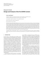
Figure 1.2. Cycloconverter using MOSFETs
The ‘equivalent cycloconverter’ was realised but replacing the thyristors with
MOSFETs—see Fig. 1.2. Each transistor has a discrete fast-recovery blocking diode in
series to provide a reverse blocking capability. By monitoring which supply phases
provide most positive or most negative voltages and switching the transistors in those
phases in an antiphase manner at high frequency, a continuous high-frequency, single-
phase current flows through the load. The International Rectifier IRF610 device was
used for the cycloconverter, and operating frequencies in excess of 100 kHz were
achieved. However, the cycloconverter requires additional control circuitry and more
C/3
C/3
C/3
LOAD
RED
YELLOW BLUE
Nam Nguyen-Quang High-frequency matrix converters for induction heating
8
complicated protection circuitry than the more common current- or voltage-fed inverter
circuits. Induced mains harmonics were also a significant problem even at the low
power levels.
Figure 1.3. Voltage-fed inverter using MOSFETs
A voltage-fed inverter, Fig. 1.3, was also considered. The parasitic diode of the
MOSFETs cannot be used to carry reactive currents because its relatively slow reverse
recovery time can cause ‘shoot-through’ conditions. Therefore, the load needs to be
excited above its resonant frequency to provide a lagging power-factor current. The
voltage-fed solution had the advantages of providing easy shut-down by switching off
the MOSFETs in the bridge, and power control using frequency modulation. However,
the paper [1.7] reported problems in protecting the transistors against short-circuit fault
conditions when the inverter operated with induction heating loads and in suffering
excessive rate of rise of voltage when the load was driven away from resonance.
Since frequency control is used to transfer power, the load is often excited away from its
resonant frequency, and hence the switches have to turn off during high reactive current
conditions, which are supported by parallel diodes—as soon as S1 begins turning off
and the current through it is reduced, the load current begins to flow through D3. This
will bring the voltage across S1 to V
DC
, less the conduction drop of diode D3, making
the switching losses of S1 significant.
S1
S2S3
S4D1
D2
D3
D4
V
DC
Nam Nguyen-Quang High-frequency matrix converters for induction heating
9
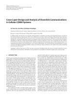
Figure 1.4. Current-fed inverter using MOSFETs as output switches
The current-fed inverter proposed in [1.7] is shown in Fig. 1.4. The inverter uses a
variable current source, which is realised by employing a controlled rectifier and a
smoothing inductor. The inverter always operates around the resonant frequency of the
load, and power control is obtained by varying the direct voltage supplied to the inverter
circuit. The author makes the point that this topology has a number of advantages,
including a low component count, low switching losses and inherent short-circuit
protection provided by the large smoothing inductor. However, this topology uses the
largest number of switching devices among the three systems, and having two switching
systems is likely to increase any problems associated with EMC. The inductor is
necessary to supply a constant current into the inverter stage, thereby creating an
effective square-wave current at the load. From the perspective of the high-frequency
current source, it will drive an effective low impedance with a parallel resonant circuit
and high impedance with a series resonant circuit. Therefore, a current-fed inverter may
induce overvoltage ‘spikes’ when feeding a series resonant load, thereby making a
parallel resonant tank circuit more suitable in this case. Moreover, to prevent the
inductor from becoming open-circuited, overlap periods have to be introduced into the
switching sequence of the inverter stage: S1 and S2 on; S1, S2, S3, and S4 on; S3 and
S4 on; S1, S2, S3, and S4 on. The paper does discuss the presence of ‘ringing’ due to
the parasitic lead inductance and the drain-to-source capacitance of the MOSFETs, and
S1
S3
S4
S2
Nam Nguyen-Quang High-frequency matrix converters for induction heating
10
emphasises the importance of a good component layout and routing to reduce the
problem. Many of the concepts pioneered in this paper remain in use, despite the
practical problems encountered with early prototypes.
In 2002, a state of the art review was conducted by H.I. Sewell [1.1]. In this work, the
author identified the most commonly used inverters for industrial heating at the time. A
brief review of sales literature and academic publications has shown that the range of
high frequency inverters has expanded in both frequency and power. At frequencies up
to 800 kHz, MOSFET-based inverters from Inductoheat Banyard can deliver up to 3
MW [1.10], or 2500 kW with Lepel’s solution [1.11]. IGBT-based inverters from Lepel
can deliver up to 1200 kW at 30 kHz [1.11]. Similarly, IGBT-based systems from RDO
Induction can deliver up to 600 kW at up to 20 kHz or up to 60 kW at up to 150 kHz
[1.12]. Cheltenham Induction Heating offer a range of solid-state inverters that can
transfer up to 120 kW in frequency range of 50 – 150 kHz [1.13]. Solid-state induction
welding units from Thermatool Europe can work from 100 to 800 kHz at power ratings
up to 1200 kW [1.14]. Similar products, using solid-state technologies, are also
available from Ajax Tocco Magnethermic [1.15], Inductelec [1.16], and Huettinger
Electronic [1.4]. These product ranges have been depicted as diamonds in Fig. 1.5 to
show current trends. Also depicted in the figure are some systems reported in journal
papers [1.17] – [1.21], marked as colour circles.
In Fig. 1.5,
red is used to depict IGBT-based systems and blue for MOSFET-based
systems. Although in some cases the switch technology is not known (marked in
black), the graph does suggest that the IGBTs are used in low frequency range and the
MOSFETs are more suitable for higher frequency ranges.
Nam Nguyen-Quang High-frequency matrix converters for induction heating
11
10
1
10
2
10
3
10
4
10
0
10
1
10
2
10
3
10
4
Inductoheat
Frequency (kHz)
Power (kW)
RDO
RDO
Ajax Tocco
Thermatool
Inductoheat
Lepel
Lepel
Cheltenham
Inductelec
Kifune et al
Bayindir et al
Okuno et al
Mollov et al
Ogiwara et al
Figure 1.5. Map of switch technology vs. power and frequency
1.2 Resonant inverters
Having examined the relationship among switch technologies, power, and frequency, it
is reasonable to explore the topologies used for industrial heating. Naturally, the
inverter will create an AC output from a DC power supply, and the DC source can be a
current source or a voltage source. High power systems usually have to draw the power
from the utility supply, which is an AC voltage source, so a current source can be
realised by rectifying the voltage source feeding an appropriately large inductance. In
summary, most systems used in practice employ current-fed inverters and voltage-
source inverters.
1.2.1 Current-fed inverter
Current-fed circuits using thyristors remain the most common inverters used in
medium-frequency induction heating applications [1.2], [1.22], [1.23], although
MOSFET-based [1.7] systems are still popular and use the same basic circuit topology.
The high-power topology, as shown in Fig. 1.4, uses a fully controlled rectifier to
supply the current to the high-frequency heating inverter. For low-power systems, a
slightly different topology, as depicted in Fig. 1.6, can be used.
Nam Nguyen-Quang High-frequency matrix converters for induction heating
12
Figure 1.6. Low-power current-source topology
By assuming that the resonant ‘tank’ circuit, comprising the work-head inductor and the
tank capacitor, behaves as a sinusoidal voltage source, and the supply to the bridge
comprising the utility supply, the rectifier and the smoothing inductor, behaves as a DC
current source, a basic operational understanding can be made. Each switch element is
a unidirectional device, which will conduct current from top to bottom. If a thyristor is
used for the switching element, then it is inherently a unidirectional device, otherwise
the switching element is generally made up of a transistor and a diode in series. The
operation of the circuit then follows in several intervals [1.7], as shown in Figs 1.7 –
1.10.
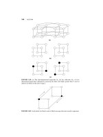
Figure 1.7. Positive half-cycle power flow
Beginning with S1 and S2 in on-state, and S3 and S4 are in off-state; when the load
voltage passes through zero, the current flow is as shown in Fig. 1.7. Since the impact
of stray inductance L1 is small and the current is effectively constant, there is
effectively no voltage across L1, and hence, the voltage across the current source is
S1
S4
S3
S2
S3
S4
S1
S2
L1
Nam Nguyen-Quang High-frequency matrix converters for induction heating
13
equal to the sinusoidal load voltage of the parallel tank. Energy is transferred from the
current source to the load circuit in this period, until S3 and S4 are switched on.
At some point during the positive half-cycle of the load current, S3 and S4 are turned
on. At this point, all switches are in the on-state, effectively shorting the output voltage
of the inverter. Just after the switching event, there can be three possible current paths,
as shown in Fig. 1.8. The current in the bottom loop will have the same magnitude as
the source current, and there will be no currents flowing in the top loop, creating no
currents going through both S3 and S4. Due to the stray inductance L1, the current in
the top loop will increase whilst the current in the bottom loop will decrease at the same
rate, making the currents through S1 and S2 fall to zero and the currents through S3 and
S4 rise to the supply current.
Figure 1.8. First inductor-commutating interval
When the currents through S1 and S2 reach zero, the switches become reverse-biased
and conduct no current, despite the driving signals. In reality, the thyristor or the in-
series diode requires a small period to recover its reverse-blocking capability. This
time, termed ‘reverse recovery time’, can vary from 20 µs to 100 µs for modern
thyristors [1.5], with longer periods belonging to larger devices. During this recovery
time, current spikes can be introduced into the load current. In Fig. 1.9, the flow of
reverse recovery currents of S1 and S2 is illustrated in dark red.
S1
S2
L1
S3
S4
Nam Nguyen-Quang High-frequency matrix converters for induction heating
14
Figure 1.9. Recovery time of the switch
Just prior to the load voltage changing polarity, S1 and S2 are switched off, and power
is returned to the supply until the load voltage changes polarity. Power is then
transferred to the tank circuit when the load voltage is in the negative half-cycle, as
shown in Fig. 1.10. At the end of this power-transfer interval, S1 and S2 are turned on
and the load current will be inverted again, repeating the cycle.
Figure 1.10. Second power-transferring interval after the safety margin
The current-source topology has its own relative merits. The first advantage is the low
reactive power flow between the power supply and the load, which means a better
utilisation of the inverter, and an interesting solution for high power systems. The
nearly constant operating frequency is another advantage, since EMC problems are
easier to ameliorate. However, there are some significant disadvantages associated with
this topology. The most obvious problem is that the parasitic inductance of the
connection between the inverter and the resonant tank undesirably affects the system
impedance. For a given current, the crossover time will be higher with longer
connection cable length. The situation becomes worse when the inverter operates at
L1
S3
S4S1
S2
S1
S2
L1
S3
S4
Nam Nguyen-Quang High-frequency matrix converters for induction heating
15
higher frequencies, because the crossover time may take a large fraction of the shorter
period. This can place upper limits on the operating frequency of and the physical
distance between the inverter and work-head. Moreover, IGBTs and MOSFETs, which
can have considerable parasitic capacitances across the power terminals, may result in
increased switching losses, when they are switched on with a large voltage across them,
in a high frequency current-fed inverter.
It has been shown that only amplitude modulation is suitable for power control in this
current-source topology, and two input power conditioning circuits for low and high
powers are as described below. Both frequency modulation, which excites the tank
away from its resonant frequency, and pulse-width modulation, which changes the
phase shift between the load voltage and current, result in lower power factor. In
addition, because the average voltages at both ends of the supply inductor have to be
equal, in steady-state, poor power factor may lead to excessive voltages on the switches.
Therefore, frequency modulation and pulse-width modulation are not applicable to the
current-source topology.
Both utility interfaces (Figs 1.4 and 1.6) have non-unity power factor, and the thyristor-
controlled rectifier may create significant distortion on the current waveform [1.23]. In
the low power interface (Fig. 1.6), a buck converter is used to control the current
through the DC link inductor, and a fixed six-pulse rectifier supplies the buck converter.
At higher power levels, the bulky DC link components make this choice uneconomic,
and therefore, a six- or twelve-pulse thyristor-based variable rectifier is normally used
in high power systems (Fig. 1.4). Significant harmonic distortion can be introduced into
the mains when these power interfaces are used. For a 5 kW power load and an ideal
utility supply, the low power interface can have the input current as shown in Fig. 1.11
using a SIMULINK model, with a relatively low DC link capacitor (100 µF). From a
Nam Nguyen-Quang High-frequency matrix converters for induction heating
16
practical perspective, the clamping effect due to the small mains line inductors and
relatively large DC link smoothing capacitor can create a trapezoidal mains voltage and
a highly distorted supply current. The power factor and the total harmonic distortion
(THD) are also known to be worse when the ratio of the drawn current to short-circuit
current of each phase is reduced [1.23]. In the low-power case, it can be expected that
poor power factors and large harmonic distortion exist due to the very small ratio of
supply current to short-circuit current. This can be improved by using additional line
inductors to increase the ratio, but at the expense of more bulky magnetic components
and less cost effective system.
20 25 30 35 40 45 50 55 60
-50
0
50
Red phase
20 25 30 35 40 45 50 55 60
-50
0
50
Yellow phase
20 25 30 35 40 45 50 55 60
-50
0
50
Time (ms)
Blue phase
Phase Voltage
Phase Current
Figure 1.11. Idealised mains input waveform for low power CSI
Significant mains distortion also exists in high power systems (Fig. 1.4). The THD of
the line current of an ideal utility supply, with an infinite DC link inductance, has been
determined to be fixed at 31.08%, despite the switching angle of the rectifier. The
mains line inductance in practical systems may slightly reduce the THD of current in
certain conditions, however, significant distortion of the supply voltage can occur due to
commutation events, where two out of three phase voltages are shorted together to
transfer the energy between the line inductances, creating line ‘notching’. For high
power systems, this can cause problems to other equipment connecting to the same
Nam Nguyen-Quang High-frequency matrix converters for induction heating
17
utility supply, and standards recommended a minimum value for the line inductances
between the rectifier and the common coupling point [1.23]. Nevertheless, because
large harmonic currents injected by the power interfaces to the utility supply may
exceed the limits specified in standards, harmonic reduction techniques are still
necessary, and many improved power quality converters, such as power factor
correctors, have been proposed.
In summary, the current source inverter has been used for most of the induction heating
systems due to its simple and straightforward approach, however, it has detrimental
effects on the utility supply, and low efficiency in high frequency systems.
1.2.2 Voltage-source inverter
Voltage-source inverters were an emerging topology at the time of the publication of the
review in [1.1]. Historically, the performance of the voltage-source inverter was
essentially ignored because of poor load regulation, slow turn-off time of the thyristors,
and slow recovery of power diodes [1.24]. However, with more modern switching
devices such as MOSFETs and IGBTs, the disadvantages are now less critical, and the
use of this topology has become a more attractive proposition.
Figure 1.12. Voltage-source topology proposed in [1.7]
The proposed topology [1.7], is shown again in Fig. 1.12. A filter network with small
inductance and large DC link capacitor is usually used to reduce the mains noise and
D1
D2
D3
D4
S1
S4
S3
S2
L
filt
C
filt