development of novel micro-embossing methods and microfluidic designs for biomedical applications
Bạn đang xem bản rút gọn của tài liệu. Xem và tải ngay bản đầy đủ của tài liệu tại đây (12.4 MB, 217 trang )
DEVELOPMENT OF NOVEL MICRO-EMBOSSING METHODS AND
MICROFLUIDIC DESIGNS FOR BIOMEDICAL APPLICATIONS
DISSERTATION
Presented in Partial Fulfillment of the Requirements for
the Degree Doctor of Philosophy in the Graduate
School of the Ohio State University
By
Chunmeng Lu, M.S.
* * * * *
The Ohio State University
2006
Dissertation Committee:
Approved by
Dr. L. James Lee, Adviser
Dr. Allen Yi _________________________________
Adviser
Dr. Avraham Benatar
Chemical Engineering Graduate Program
UMI Number: 3230881
3230881
2006
UMI Microform
Copyright
All rights reserved. This microform edition is protected against
unauthorized copying under Title 17, United States Code.
ProQuest Information and Learning Company
300 North Zeeb Road
P.O. Box 1346
Ann Arbor, MI 48106-1346
by ProQuest Information and Learning Company.
ii
ABSTRACT
The goal of this study is to develop novel microfabrication methods and
microfluidic devices for BioMEMS applications. The emphasis is on the development of
new hot embossing techniques, the design of microfluidic functions and biocompatible
packaging methods for polymeric microfluidic chips.
First, two unconventional hot embossing techniques were developed: laser
assisted and sacrificial template based hot embossing. In laser assisted embossing,
localized micro patterning can be achieved on polymer surfaces with a cycle time of less
than 1 minute due to the localized heating, which is comparable with that of micro
injection molding. The sacrificial template based hot embossing solved the de-molding
issue involved in conventional hot embossing especially for high aspect ratio
microstructures. Embossing of microstructures with aspect ratio of 6 was demonstrated
successfully and the possibility of laser assisted embossing in conjunction with sacrificial
template embossing was investigated.
A fishbone microvalve was designed based on the concept of super-
hydrophobicity such that the valve function remains after protein blocking, a required
step in some enzyme-linked immuno-sorbent assays (ELISA) applications to prevent
non-specific binding. Compared with another type of super-hydrophobic microvalve
iii
developed based on the micro-/nano structure formation by chemical synthesis, the
fishbone valve can be easily incorporated into the microfluidic designs. Polymer
compact-disk (CD) microfluidic platform integrated with different fluidic features was
designed and fabricated. We have demonstrated successfully that flow sequencing can be
achieved on a CD-like microfluidic platform.
For packaging microfluidic platforms, a new interstitial bonding technique has
been developed, which bonds the polymer-based microfluidic platforms without
introducing any alien materials in to microchannels. This method can easily bond
biochips with complex flow patterns, but in a relatively smaller size. A multi-channel
DNA sequencing chip was demonstrated experimentally. Another bonding method, CO
2
assisted bonding, was also demonstrated for bonding a 5-inch CD platform. By applying
a thin PLGA interlayer, the CD platform can be bonded at low temperature and low
pressure to achieve a hermetic bonding. ELISA tests showed that both bonding methods
have no or little effect on the activity of preloaded proteins, which is essential for
microfluidic designs that requires preloading of some regents such as proteins,
antibody/antigen and cells.
iv
Dedicated to my wife
v
ACKNOWLEDGMENTS
First I would like to express my sincere appreciations to my adviser, Professor L.
James Lee, for his invaluable guidance, discussions, supports and encouragements
throughout my five years stay at The Ohio State University. Many thanks to him for his
frequent discussions with me about my general research directions and technical details
which not only expanded my horizons but also stimulated my creativity and imagination.
I would also like to acknowledge Professor L. James Lee for bringing me into this
wonderful field and provide financial support to me.
I would like to thank Dr. Avraham Benatar, Dr. David Grewell, and Ms. Miranda
Marcus for their valuable discussion and generous help in my experiments related to laser
heating.
Thanks go to Professors Allen Yi, Avarham Benatar, and John C. Byrd for serving on
my dissertation committee and for their invaluable comments and suggestions, to Paula
and Stacy for proofreading all the manuscripts I submitted for publishing.
Thanks also go to my collaborators, Dr. Hank Wu, Dr. Chu-hua Chen, and all other
friends in Ritek, Taiwan, on the CD-ELISA project.
To all the fellow graduate students in our lab, especially to those who collaborated
with me (Yi-Je Juang, Chee-Guan Koh, Yong Yang, Jingjiao Guang, Shengnian Wang,
Yubing Xie, Ling Li, Xia Cao, Hongyan He and etc.), I would say thank you very much
vi
for your friendship and I cherish the moments we shared together very much!
Experimental assistances from Dr. Mark Ming-cheng Cheng and Derek Ditmer in
MicroMD are greatly appreciated.
I also want to give my special thanks to Paul Green and Leigh Edward for their
endless help on the machining and other supporting efforts in my experimental work.
Last but not least, I want to thank my family for their love and dedications for
encouraging and supporting me. Great appreciations to my wife, Chunyan, for her love,
accompany, encouragement, and support through all these years.
vii
VITA
August 16, 1971 Born in Xushui, Hebei, P.R. China
September 1989 - July 1993 B.S. Mechanical Engineering,
Beijing University of Chemical Tech.
Beijing, P.R. China
July 1993 - July 1998 Mechanical Engineer,
Hebei Aika Packaging Materials Co. Ltd.
Shijiazhuang, Hebei, P.R. China
Sept. 1998 - June 2001 M.S. Mechanical Engineering
The Institute of Plastics Machiner and
Engineering (IPME) in
Beijing University of Chemical Tech.
Beijing, P.R. China
September 2001 – August 2002 University Fellowship
Chemical and Biomolecular Engineering
The Ohio State University
Columbus, Ohio, USA
September 2002 – Present Graduate Research Associate
Chemical and Biomolecular Engineering
The Ohio State University
Columbus, Ohio, USA
PUBLICATIONS
1. Chunmeng Lu, Yi-Je Juang, L. James Lee, David Grewell, Avraham Benatar,
Analysis of laser/IR-assisted microembossing, P
olymer Engineering & Science, 45(5),
661-668 (2005).
viii
2. Yi-Je Juang, Xin Hu, Shengnian Wang, L. James Lee, Chunmeng Lu and Jingjiao
Guan, Electrokenetic Interactions in Mcroscale Cross-slot Flow, Applied Physics Letters,
87, 244105-244105-3 (2005).
3. David Grewell, Chunmeng Lu, Abbass Mokhtarzadeh, Avraham Benatar and L.
James Lee, Feasibility of selected methods for embossing micro-features in
thermoplastics, (SPE 2003, Nashville).
4. Chunmeng Lu and L. James Lee, Numerical simulation of Laser/IR Assisted Micro-
Embossing (SPE 2004, Chicago).
5. David Grewell, Chunmeng Lu, L. James Lee and Avraham Benatar, Infrared micro-
embossing of thermoplastics (SPE 2004, Chicago).
6. Chunmeng Lu, L. James Lee, David Grewell and Avraham Benatar, Sacrificial
material assisted laser welding of polymeric micro channels (SPE 2005, Boston).
7. Hae Woon Choi, Chunmeng Lu, L. James Lee and Dave Farson, Femtosecond laser
micromachining of internal microfluidic channels in PMMA, (ASPE 2005, OSU).
8. Chunmeng Lu, Yi-Je Juang and L. James Lee, Numerical simulation of Laser/IR-
assisted Micro-Embossing in Polymer (Numiform 2004, OSU).
9. Chunmeng Lu and L. James Lee, Numerical simulation of Laser/IR-assisted Micro-
Embossing in Polymer (PPS-20, Akron, USA).
10. Chunmeng Lu and L. James Lee, Sacrificial mold embossing for high density/aspect
ratio micro-/nano structures (PPS-22, Yamagata, Japan).
11. Michael W. Bobem, Chunmeng Lu, Kurt W. Koelling and L. James Lee,
Fundamental processing characteristics in polymer micro/nano molding (SPE 2006,
Charlotte, USA).
12. Chunmeng Lu and L. James Lee, Sacrificial mold embossing for high density, high
aspect ratio micro/nano structures (SPE 2006, Charlotte, USA).
13. Chunmeng Lu and L. James Lee, Micro-valve based on super-hydrophobicity (SPE
2006, Charlotte, USA).
ix
14. Kittichai Sojiphan, Miranda Marcus, Hae Woon Choi, Chunmeng Lu, Avraham
Benatar and L. James Lee, Beam Shaping with Diffractive Optics for Laser Micro-
Machining of Plastics with a Femtosecond Laser (SPE 2006, Charlotte, USA).
15. L. James Lee, Chunmeng Lu, Yi-Je Juang and Shang-Tian Yang, Interstitial bonding
for plastic microfluidic chips, US Provisional Patent Application, 60/741,697, Dec 2,
2005
16. L. James Lee, Chunmeng Lu, Yi Je Juang and Shang-Tian Yang, Design of super-
hydrophobic valve for plastic microfluidic chips, US Porvisional Patent Application,
60/738,096, Nov. 18, 2005
FIELDS OF STUDY
Major Field: Chemical Engineering
Minor: Microfluidics and Polymer Microfabrication
x
TABLE OF CONTENTS
Page
Abstract ii
Dedication iv
Acknowledgments v
Vita vii
List of Tables xiv
List of Figures xv
Chapters:
1. Introduction 1
1.1. Microfabrication 1
1.2. Microfluidics…. …………………………………………………… 4
1.3. Outline………………………… ………………………………… 6
2. Literature review 7
2.1. Polymer replication 8
2.1.1. Reactive casting………….… 10
2.1.2. Injection molding……………………. 11
2.1.3. Hotembossing 13
2.2. Mold materials and operation parameters…………………………… 16
2.3. Polymeric substrate materials…………….
2.4. Master fabrications…………………………………………………
2.5. Nanostructure replication…………………………………………….
2.5.1. Hot embossing lithography (HEL)……………………………
2.5.2. Soft lithography……………………………………………….
2.6. Chip packaging……………………………………………………….
2.6.1. Solvent bonding………………………………………………
2.6.2. Ultrasonic welding……………………………………………
2.6.3. Laser welding…………………………………………………
19
22
24
24
26
27
30
32
33
xi
2.7. De-molding issues……………………………………………………
2.8. Microfluidic devices…………………………………………………
2.8.1 Microfluidic functions…………………………………………
2.8.1.1. Pumping………………………………………………….
2.8.1.2. Valving…………………………………………………
2.8.1.3. Micromixing……………………………………………
2.8.1.4. Sampling/metering……………………………………….
2.8.2. Immnuoassays………………………………………………….
2.8.2.1. Immunoassay……………………………………………
2.8.2.2. Enzyme-linked immunosorbent assay (ELIA)…………
2.8.2.3. Compact-Disk based ELISA (CD-ELISA)………………
36
39
42
42
45
46
48
49
49
49
50
3. Laser-assisted micro-embossing………………………………… 55
3.1. Background 56
3.2. Experimental 63
3.2.1. Equipment and materials 62
3.2.2. Methodology……… 66
3.2.3. Simulation… 69
3.3. Results and discussion 73
3.3.1. Experimental 73
3.3.2. Simulation 78
3.4. Conclusions 88
4. Sacrificial template based micro-embossing 89
4.1. Background 89
4.2. Experimental 91
4.2.1. Materials 91
4.2.2. Mold preparation………… 92
4.2.2.1.SU-8 master fabrication
4.2.2.2.PDMS replicates (daughter mold)………………………
4.2.2.3.Sacrificial templates……………………………………….
92
93
93
4.2.3. Hot embossing
4.2.4. Laser/IR surface heating assisted sacrificial template micro-
embossing……………………………………………………
4.2.5. FEM simulation………………………………………………
97
98
99
4.3. Results and discussion 100
4.3.1. SU-8 mater fabrication………………… 100
4.3.2. PDMS replicates (daughter mold)…………… 101
4.3.3. Sacrificial template………………… 102
4.3.4. Hot embossing…………………………
4.3.5. Laser/IR surface heating assisted sacrificial template micro-
embossing……………………………………………………….
103
106
4.4. Conclusions 110
xii
5. Fishbone valve and protein benign bonding desing……………………… 111
5.1. Background 111
5.2. Experimental 113
5.2.1. Valving…
5.2.1.1.Materials and reagents……………………………………
5.2.1.2.Fabrication of super-hydrophobic surface………………
5.2.1.3.Contact angle measurement……………………………….
5.2.1.4.‘Fishbone’ valve design…………………………………
5.2.1.5.Chip fabrication…………………………………………
5.2.1.6.Protein blocking…………………………………………
5.2.1.7.Valve testing………………………………………………
113
113
114
114
115
116
116
117
5.2.2. Packaging…………
5.2.2.1.Materials and reagents……………………………………
5.2.2.2.CO
2
assisted bonding……………………………………
5.2.2.3.Protein activity test………………………………………
121
119
119
123
5.3. Results and discussions… 125
5.3.1. Valving……………………………
5.3.1.1.Super-hydrophobic surface……………………………….
5.3.1.2.Performance of conventional capillary valve……………
5.3.1.3.Performance of fishbone valve……………………………
125
125
127
127
5.3.2. CO
2
assisted bonding……………………………… 129
5.4. Conclusions 133
6. Conclusions and recommendations 134
6.1. Conclusions 134
6.2. Recommendations 136
6.2.1. Application of new laser heating techniques 136
6.2.2. Application of numerical analysis 139
6.2.3. CD-ELISA-toward commercialization 144
Appendix A: Interstitial bonding 147
A.1. Background 147
A.2. Experimental……………………
A.2.1. Interstitial bonding…………………………………………
A.2.1.1. Materials………………………………………………
A.2.1.2. Interstitial bonding……………………………………
A.2.2. DNA separation……………………………………………
A.2.2.1. Materials and reagents…………………………………
A.2.2.2. Microchip fabrication……………………………………
A.2.2.3. Detailed DNA separation process……………………
150
150
150
150
151
151
151
154
A.3. Results and discussion 156
A.4. Conclusion……… 160
xiii
Appendix B: Super-hydrophobic valve study ………………………………
B.1. Background…………………………………………………………
B.2. Experimental…………………………………………………………
B.2.1. Materials and reagents…………………………………………
B.2.2. Nanostructured surface………………………………………
B.2.2.1. Surface depostion………………………………………
B.2.2.2. Plasma treatment…………………………………………
B.2.2.3. Surface characterization………………………………….
B.2.3. Super-hydrophobic valve………………………………………
B.2.3.1. Chip design………………………………………………
B.2.3.2. Chip fabrication………………………………………….
B.2.3.3. Valve capacity test……………………………………….
B.3. Results and discussions………………………………………………
B.3.1. Hierarchical surface……………………………………………
B.3.1.1. Surface characterization………………………………….
B.3.1.2. Proposed mechanism…………………………………….
B.3.2. Contact angle measurement……………………………………
B.3.3. Super-hydrophobic valve………………………………………
B.4. Conclusion…………………………………………………………
161
161
164
164
165
165
165
166
166
166
167
168
169
169
169
173
175
176
177
Bibliography 178
xiv
LIST OF TABLES
Table Page
2.1 Comparison between molding methods…………………………………… 9
2.2 Comparison of performance between 96-well plate and microchannel… 54
4.1 Comparison between different water-soluble materials as candidates of
sacrificial template…………………………………………………………
4.2 Thermal properties of UV cured PVP……………………………………
5.1 Dimensional parameters and burst frequency of the 5-reservoir CD-chip
design………………………………………………………………………
5.2 Contact angle of 0.2wt% BSA solution on various surfaces………………
A.1 DNA separation parameters………………………………………………
94
103
121
126
156
xv
LIST OF FIGURES
Figure Page
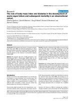
1.1 Schematic of the hot embossing process………………… 2
2.1 Experimental setup for TTIr scan microwelding of PC and
PS ………………………………………………………………
34
2.2 Schematic of mask welding …………… 35
2.3 Photograph of "lab-on-a-chip" product ………………… 40
2.4 Schematic of Capillary valve ………………… 46
2.5 Schematic of (a)a CD-ELISA design with 24 sets of assays, (b) a
single assay (1. waste; 2. detection; 3. first antibody; 4,6,8,10.
washing; 5. blocking protein; 7. antigen sample; 9. second
antibody; and 11. substrate), and (c) photo of a single
assay………………… ……
52
3.1 Photograph of channel produced with IR embossing of high
density polyethylene (a) cross section the mold replicate (b) and
(c) top and cross section views of the embossed HDPE
microchannel
58
3.2 Micro channel sample with ultrasonic embossing … 59
3.3 Micro channel sample with hot air embossing ………………… 60
3.4 Picture of the Branson BRAM laser welding equipment……… 64
3.5 Dog-bone shaped mold and (b) single-channel mold 65
3.6 Schematics of Laser/IR-Assisted micro-embossing (a)
Transparent Mold Embossing (TME) (b) Transparent Substrate
Embossing (TSE)………………………………………………
67
3.7 (a) Schematic and (b) experimental setup of laser transmission
measurement……………………………………………………
71
xvi
3.8 Channel depth as a function of time at various laser powers
(clear mold-no preheating)……………………………………….
73
3.9 Channel depth as a function of preheating time………………….
75
3.10 Channel depth as a function of heating time with black mold…
76
3.11 Tool damage after de-molding…………………………………
77
3.12 Coss section of the epoxy mold and embossed sample…………
78
3.13 Transmittance of carbon black filled polymers: Epoxy (2.0wt%
carbon black) and PMMA (0.5wt% carbon black)………………
79
3.14 Comparison between temperature distributions with and without
considering IR radiation penetration (PMMA, 100% power
level, 2.5 seconds preheating, 0.5-wt% carbon black)…………
80
3.15 Polymer flow pattern in TSE (PMMA; force: 100 N; power
level: 50%) (a) Simulated temperature distribution in the
substrate at 8 seconds, (b) simulated flow pattern and (c) an
embossed sample…………………………………………………
81
3.16 Polymer flow pattern in TME (0.5wt% carbon black filled
PMMA; force: 100 N; power level: 100%) (a) Initial temperature
distribution in the substrate at 2 seconds, (b) simulated flow
pattern and (c) an embossed sample……………………………
83
3.17 Simulated flow pattern in isothermal embossing (PMMA, 170
°C, 100 N)………………………………………………………
80
3.18 The calculated temperature distribution inside 0.5wt% carbon
black filled PMMA substrate with (a) 1 second and (b) 2 seconds
preheating time at 100% power (Substrate is 2 mm in thickness
and 10 mm in width)……………………………………………
84
3.19 Simulated and experimental flow pattern in TSE at different
heating times (Viewed in x-y plane) (a) 6 seconds, (b) 10
seconds, and (c) 14 seconds (PMMA; Power level: 50%; Force:
240N)……………………………………………………………
85
3.20 Simulated and experimental mold displacement curve in TSE
(Filled symbol: Simulation; Empty symbol: Experimental)……
85
xvii
3.21 Simulated and experimental flow pattern in TME (Viewed in x-y
plane) (PMMA with 0.5wt% carbon black; Power level: 100%;
Force: 240N) (a) Preheating time: 1 second (b) Preheating time:
2 seconds…………………………………………………………
87
3.22 Simulated and experimental mold displacement curve
(Preheating time: 2 seconds)……………………………………
87
4.1 a) Schematic of reactive mold to prepare a PVP sacrificial
template. (b) A SU-8 mold with microchannel array. (c)Cross
section and (d) top views of a PVP microchannel array prepared
by reactive molding………………………………………………
95
4.2 Schematic of solvent molding to prepare a PVP sacrificial
template…………………………………………………………
96
4.3 Schematic of the setup for embossing of microporous membrane
with a sacrificial bi-layer. (b) Embossed microporous membrane
with PLGA……………………………………………………….
98
4.4 (a) SU-8 master mold with micropillar array. (b) Replicated
PDMS daughter mold. (c) Replicated PVP sacrificial template…
101
4.5 (a) Cross section and (b) top view of the PVP sacrificial template
prepared by solvent molding, (c) the photo of a ceramic wafer
with microfeatures via solvent molding………………………….
104
4.6 (a) Embossed multi-channel array on PMMA non-isothermally.
Eossed micro-pillar array on PMMA isothermally at pressures of
(a) 1.6Mpa and (b) 0.34Mpa …………… ……………………
105
4.7 Embossed (a) PMMA and (b) PLGA microwell array with PVP
sacrificial templates. (c) Embossed PLGA with a SU-8 mold…
106
4.8 Embossed PMMA single channel (a) isothermally and (b) non-
isothermally using laser/IR surface heating……………………
107
4.9 Simulation results of isothermal micro-embossing at
temperatures of (a)130°C and (b) 150°C………………………
108
4.10 Simulated initial temperature distribution of PMMA substrate
with surface heating……………………………………………
108
4.11 Simulated (a) temperature distribution and (b) material flow of
laser/IR surface heating assisted sacrificial template embossing
109
xviii
5.1 Schematics of (a) fish-bone valve and (c) conventional capillary
valve design………………………………………………………
115
5.2 Photos and schematics of (a) the cross section and (b) the top
view of the capillary forces working on the liquid front at the
edge of the valve…………………………………………………
117
5.3 (a) Schematic of conventional capillary valving. (b) CAD design
of a 5-well CD-chip for flow sequencing………………………
118
5.4 Schematic of CO
2
assisted bonding device………………………
122
5.5 Images of water droplets on various surfaces: (a) PMMA, (b)
fluorine plasma treated PMMA, and (c) Microfeatured PMMA
with fluorine plasma treatment…………………………………
125
5.6 (a) Capillary valve can stop the flow of pure water and protein
solution. (b) Capillary valve fails to stop the 0.2wt% BSA
solution with food dye after protein blocking. (c) With the
fluorine plasma treatment, capillary valve still loses its function.
127
5.7 (a) Fishbone valve is able to stop the flow of 0.2wt.% BSA
solution with food dye after protein blocking. Flow profile of
protein blocking solution in microchannel (c) with and (d)
without fluorine plasma surface modification……………………
128
5.8 CO
2
bonded 5-inch CD-ELISA chip……………………………
130
5.9 (a) Cross section and (b) top view of a CO
2
bonded chip tested
with food dye solution……………………………………………
131
5.10 Effect of bonding conditions on (a) the protein content of BSA,
(b) the bioactivity of lysozyme, and (c) the fluorescence signal
of Alexa Fluor® 488 goat anti - rabbit IgG………………………
132
6.1 Schematic of light diffraction……………………………………. 134
6.2 Diffractive optics…………………………………………………
138
6.3 Picture of the (a) circular and (b) the cross pattern heated
affected zone……………………………………………………
139
6.4 Smulation results of (a) Pristine PMMA surface and (b) plasma
treated PMMA……………………………………………………
143
A.1 Schematic of interstitial bonding…………………………………
151
A.2 DNA chip design………………………………………………… 153
xix
A.3 Schematic of (a). microfluidic chip design and resin loading, (b)
resin curing for bonding………………………………………….
153
A.4 Nikon Epi-Fluorescence Microscopy…………………………….
154
A.5 Schematic of DNA chip and electrode numbers…………………
156
A.6 cross section of (a) interstitial and (b) CO2 bonded microchanne.
157
A.7 (a). Interstitial space filled with food dye (b). Microchannels of
the bonded microfluidic chip filled with food dye……………….
157
A.8 DNAseparation result…………………………………………….
159
A.9 Separation result from the literature……………………………
159
B.1 Schematic of hydrophobic valve…………………………………
163
B.2 Microvalve chip design…………………………………………
167
B.3 Motor test setup…………………………………………………
168
B.4 SEM of (a) single layer Pani, (b) single layer Ppy, (c) double
layer Pani, and (d) Pani/Ppy on PMMA surface after 2 min
fluorine plasma treatment………………………………………
170
B.5 SEM of Pani/Ppy coated PMMA surface after (a) 0, (b) 2 min (c)
4min and (d) 10 min fluorine plasma treatement………………
171
B.6 SEM of Pani/Pani coated PMMA surface after (a) 0, (b) 2 min
(c) 4min and (d) 10 min fluorine plasma treatement…………….
172
B.7 Proposed mechanism of surface morphology evolution for
Pani/Ppy double layer on PMMA………………………………
174
B.8 Photo of water profile on achieved super-hydrophobic surface
(a) before and (b) after protein treatment for Pani/Ppy double
layer on PMMA after 2 min fluorine plasma treatement………
176
B.9 Valve capacity test……………………………………………….
177
1
CHAPTER 1
INTRODUCTION
This Theis covers two major parts: polymer micro-embossing and polymer based
microfluidic biochips. They are briefly introduced in the following sections.
1.1 Microfabrication
Over the past two decades, fabrication techniques of polymer based micro- and
nano-structures have been widely explored for bio- and chemical-MEMS (micro-electro-
mechanical-system) applications. A variety of methods are available to manufacture
micro-features including lithography, soft lithography, micro-injection molding, and hot
embossing. While advances have been made with all of these methods, they remain as
slow batch processes. Lithography and soft lithography techniques are multi-step batch
processes that have relatively long cycle times and are expensive. Micro-injection
molding is better suited for mass production although it requires longer cycle times than
in conventional injection molding. Also, molds for micro-injection molding are very
expensive. Among them, the hot embossing process provides several advantages such as
relatively low cost for the embossing tools, the simplicity of the process, the high
replication accuracy for small features, and the relatively high throughput. A schematic
of the hot embossing is shown in Figure 1.1. It can be operated in both cyclic and
continuous modes. The basic principle is that a polymer substrate is first heated above its
softening temperature, usually glass temperature (T
g
) for amorphous polymers. A mold
(or master) fabricated by either CNC-machining or lithographic methods with subsequent
electroplating or casting procedure is then pressed against the substrate, allowing the
pattern to be fully transferred onto the substrate (embossing). After a certain time of
contact between the mold and the substrate, the system is cooled down below T
g
,
followed by separating the mold and the substrate (de-embossing).
Mold
polymer sheet
force
cooling device
Cyclic Process
Continuous Process
press
heating zones
mold
belt
polymer sheet
force
Mold
polymer sheet
force
cooling device
Cyclic Process
Continuous Process
press
heating zones
mold
belt
polymer sheet
force
Figurer 1.1 Schematic of hot embossing process
The hot embossing processes have been applied in the industry for many years
and the fundamental understanding of the relationships among material properties,
2
3
processing conditions and part quality has been widely investigated [Y,-J. Juang, 2001,
Part I and Part II]. Typically, polymers are processed near the glass transition temperature
uner the isothermal conditions in the conventional hot embossing process. However, the
conventional hot embossing process has some inherent drawbacks such as the long cycle
time because of the isothermal process, in which the whole substrate must be heated
above its glass transition temperature before embossing and cooled down after
embossing. Another common issue is de-embossing, during which damage to the mold
and/or the substrate is a major mode of failure. This is the common issue for both hot
embossing and micro-injection molding. Various methods have been tried to solve this
problem, including using molds with positive draft angles, and surface modification of
the mold, but only limited success was achieved, especially for high aspect ratio
microstructures.
In this study, we report on a fast heating method to achieve the reduced cycle time
comparable to that micro-injection molding by rapid heating to soften or melt the
polymer on the surface while pressing it against a mold to form the micro-features. This
approach capitalizes on the advantages of hot embossing while reducing the cycle time to
offer an opportunity for continuous manufacturing. We have also developed a sacrificial
template based micro-embossing technique, using the water soluble material to solve the
de-molding issue by dissolving the template in an environmentally benign solvent. We
also carried out systematic experiments and compared the part quality under various
processing conditions. In addition, FEM simulation was conducted to describe the flow
behavior in hot embossing process. Through such quantitative analysis, we tried to link
both fast surface heating and sacrificial template technique in the hot embossing process.
4
1.2 Microfluidics
The demand for high-precision miniature devices and efficient processing
technologies for micro-/nano-fabrication has been growing rapidly. Emerging markets
include chemical and medical devices (e.g. gene-chips, hearing aids, drug delivery
systems, bio-sensors, fuel cells) [Freemantle, 1999]; telecommunication components;
optical components (e.g. diffraction gratings, miniature lens and mirrors); automotive
crash, acceleration and distance sensors; camera and watch components [Snyder, 1999];
and mechanical devices (e.g. printer heads, micro heat exchangers).
The major technical challenges in making these microsystems include: design and
implementation of necessary microfluidic functions; integration of these functions with
complete automation; and development of cost-effective manufacturing technology
[Madou 2001]. Microfluidics is the manipulation of fluids in channels having at least
two dimensions at the micron scale. It is a core technology in a number of miniaturized
systems developed for chemical, biological, and medical applications [Freemantle, 1999].
Major microfluidic components include sample introduction or loading (and in
some cases, sample preparation); propulsion of fluids (such as samples to be analyzed,
reagents, and wash and calibration fluids) through micron-sized channels; valving; fluid
mixing and isolation as desired; small volume sample metering; sample splitting and
washing; and temperature control of the fluids. A wide range of microfluidic components
such as micropumps, microvalves, micromixers, flow sensor, etc., have been
demonstrated. The main challenge in making miniaturized systems is the integration of
different microfluidic components to perform certain functions at high speed and high
throughput. Integrated microfluidic systems have the potential for applications such as
5
microreaction technology, on-chip flow-through-PCR (polymerase chain reaction), bio-
separation, clinical diagnostics, drug discovery and delivery, lab-on-a-chip technology,
air bag triggers, and ink jet nozzles [McDonald, 2000].
A microfluidic platform has been designed on a compact-disk (CD) for medical
diagnostics, which includes functions such as pumping, valving, sample/reagent loading,
mixing, metering, and separation. The fluid propulsion is based on centrifugal force,
which is achieved through rotationally induced hydrostatic pressure. A passive capillary
valve, which is based on a pressure barrier that develops when the cross-section of the
capillary expands abruptly, was used to control the fluid flow [Lai, 2002]. However, in
enzyme-linked immuno-sorbent assay (ELISA) applications, all the reservoirs and
channel surfaces need to be blocked to prevent non-specific binding for increased testing
accuracy. After protein blocking, these capillary valves lost their function due to the
change of the surface property.
We have developed a fishbone microvalve based on the concept of super-
hydrophobicity, which can solve the issue related to protein blocking. Various methods
to achieve a super-hydrophobic surface and the influence of protein on the surface
properties were investigated. We successfully demonstrated that, flow sequencing can be
achieved on a CD-like microfluidic platform after protein blocking by integrating the
necessary microfluidic functions such as centrifuge pumping and fishbone valving.
In most BioMEMS applications, biocompatibility is one of the main requirements
for a fabrication process due to the presence of proteins and even cells on the device. For
example, protein or antibody needs to be pre-loaded onto the channel surface before