HƯỚNG dẫn sử DỤNG PLC s7 200
Bạn đang xem bản rút gọn của tài liệu. Xem và tải ngay bản đầy đủ của tài liệu tại đây (109.12 KB, 15 trang )
S7-200 Programmable Controller System Manual
118
High-Speed Counter Instructions
High -Speed Counter Definition
The High-Speed Counter Definition instruction (HDEF)
selects the operating mode of a specific high-speed counter
(HSCx). The mode selection defines the clock, direction,
start, and reset functions of the high-speed counter.
You use one High-Speed Counter Definition instruction for
each high-speed counter.
Error conditions that set ENO = 0
1 0003 (input point conflict)
1 0004 (illegal instruction in int errupt)
1 000A (HSC redefinition)
High -Speed Counter
The High-Speed Counter (HSC) instruction configures and
controls the high-speed counter, based on the state of the
HSC special memory bits. The parameter N specifies the
high-speed counter number.
The high-speed counters can be configured for up to twelve different modes of operation. See
Table 6-26.
Each counter has dedicated inputs for clocks, direction control, reset, and start, where these
functions are supported. For the two-phase counters, both clocks can run at their maximum
rates. In quadrature modes, you can select one times (1x) or four times (4x) the maximum
counting rates. All counters run at maximum rates without interfering with one another.
Error conditions that set ENO = 0
1 0001 (HSC before HDEF)
1 0005 (simultaneous HSC/PLS)
Table 6-25 Valid Operands for the High-Speed Counter Instructions
Inputs/Outputs Data Types Operands
HSC, MODE BYTE Constant
N WORD Constant
Refer to the Programming Tips on the documentation CD for programs that use high-speed
counters. See Tip 4 and Tip 29.
High-speed counters count high-speed events that cannot be controlled at S7-200 scan rates.
The maximum counting frequency of a high-speed counter depends upon your S7-200 CPU
model. Refer to Appendix A for more information.
Tip
CPU 221 and CPU 222 support four high-speed counters: HSC0, HSC3, HSC4, and HSC5.
These CPUs do not support HSC1 and HSC2.
CPU 224, CPU 224XP, and CPU 226 support six high-speed counters: HSC0 to HSC5.
Programming
Tips
S7-200 Instruction Set Chapter 6
119
Typically, a high-speed counter is used as the drive for a drum timer, where a shaft rotating at a
constant speed is fitted with an incremental shaft encoder. The shaft encoder provides a specified
number of counts per revolution and a reset pulse that occurs once per revolution. The clock(s)
and the reset pulse from the shaft encoder provide the inputs to the high-speed counter.
The high-speed counter is loaded with the first of several presets, and the desired outputs are
activated for the time period where the current count is less than the current preset. The counter is
set up to provide an interrupt when the current count is equal to preset and also when reset
occurs.
As each current-count-value-equals-preset-value interrupt event occurs, a new preset is loaded
and the next state for the outputs is set. When the reset interrupt event occurs, the first preset and
the first output states are set, and the cycle is repeated.
Since the interrupts occur at a much lower rate than the counting rates of the high-speed
counters, precise control of high-speed operations can be implemented with relatively minor
impact to the overall PLC scan cycle. The method of interrupt attachment allows each load of a
new preset to be performed in a separate interrupt routine for easy state control. (Alternatively, all
interrupt events can be processed in a single interrupt routine.)
Understanding the Different High-Speed Counters
All counters function the same way for the same counter mode of operation. There are four basic
types of counters: single-phase counter with internal direction control, single-phase counter with
external direction control, two-phase counter with 2 clock inputs, and A/B phase quadrature
counter. Note that every mode is not supported by every counter. You can use each type: without
reset or start inputs, with reset and without start, or with both start and reset inputs.
When you activate the reset input, it clears the current value and holds it clear until you
deactivate reset.
When you activate the start input, it allows the counter to count. While start is deactivated,
the current value of the counter is held constant and clocking events are ignored.
If reset is activated while start is inactive, the reset is ignored and the current value is not
changed. If the start input becomes active while the reset input is active, the current value is
cleared.
Before you use a high-speed counter, you use the HDEF instruction (High-Speed Counter
Definition) to select a counter mode. Use the first scan memory bit, SM0.1 (this bit is turned on for
the first scan and is then turned off), to call a subroutine that contains the HDEF instruction.
Programming a High-Speed Counter
You can use the HSC Instruction Wizard to configure the counter. The wizard uses the following
information: type and mode of counter, counter preset value, counter current value, and initial
counting direction. To start the HSC Instruction Wizard, select the Tools > Instruction Wizard
menu command and then select HSC from the Instruction Wizard window.
To program a high-speed counter, you must perform the following basic tasks:
Define the counter and mode.
Set the control byte.
Set the current value (starting value).
Set the preset value (target value).
Assign and enable the interrupt routine.
Activate the high-speed counter.
Instruction
Wizard
S7-200 Programmable Controller System Manual
120
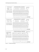
Defining Counter Modes and Inputs
Use the High-Speed Counter Definition instruction to define the counter modes and inputs.
Table 6-26 shows the inputs used for the clock, direction control, reset, and start functions
associated with the high-speed counters. The same input cannot be used for two different
functions, but any input not being used by the present mode of its high-speed counter can be
used for another purpose. For example, if HSC0 is being used in mode 1, which uses I0.0 and
I0.2, I0.1 can be used for edge interrupts or for HSC3.
Tip
Note that all modes of HSC0 (except mode 12) always use I0.0 and all modes of HSC4 always
use I0.3, so these points are never available for other uses when these counters are in use.
Table 6-26 Inputs for the High-Speed Counters
Mode Description Inputs
HSC0 I0.0 I0.1 I0.2
HSC1 I0.6 I0.7 I1.0 I1.1
HSC2 I1.2 I1.3 I1.4 I1.5
HSC3 I0.1
HSC4 I0.3 I0.4 I0.5
HSC5 I0.4
0
Single-phase counter with internal
d
i
t
i
t
l
Clock
1
direction control
Clock Reset
2 Clock Reset Start
3
Single-phase counter with external
d
i
t
i
t
l
Clock Direction
4
direction control
Clock Direction Reset
5 Clock Direction Reset Start
6
Two-phase counter with 2 clock inputs
Clock Up Clock Down
7 Clock Up Clock Down Reset
8 Clock Up Clock Down Reset Start
9
A/B phase quadrature counter
Clock A Clock B
10 Clock A Clock B Reset
11 Clock A Clock B Reset Start
12 Only HSC0 and HSC3 support
mode12.
HSC0 counts the number of pulses
going out of Q0.0.
HSC3 counts the number of pulses
going out of Q0.1.
S7-200 Instruction Set Chapter 6
121
Examples of HSC Modes
The timing diagrams in Figure 6-22 through Figure 6-26 show how each counter functions
according to mode.
Clock 0
1
Internal
Direction
Control
(1 = Up)
0
1
0
Current value loaded to 0, preset loaded to 4, counting direction set to up.
Counter enable bit set to enabled.
Counter
Current
Value
PV=CV interrupt generated
Direction changed within interrupt routine
1
2
3
4
3
2
1
0
1
Figure 6-22 Operation Example of Modes 0, 1, or 2
2
1
Clock
0
1
External
Direction
Control
(1 = Up)
0
1
0
Current value loaded to 0, preset loaded to 4, counting direction set to up.
Counter enable bit set to enabled.
Counter
Current
Value
PV=CV interrupt generated
1
2
PV=CV interrupt generated and
Direction Changed interrupt generated
3
4
5
4
3
Figure 6-23 Operation Example of Modes 3, 4, or 5
S7-200 Programmable Controller System Manual
122
When you use counting modes 6, 7, or 8, and rising edges on both the up clock and down clock
inputs occur within 0.3 microseconds of each other, the high-speed counter could see these
events as happening simultaneously. If this happens, the current value is unchanged and no
change in counting direction is indicated. As long as the separation between rising edges of the
up and down clock inputs is greater than this time period, the high-speed counter captures each
event separately. In either case, no error is generated and the counter maintains the correct count
value.
Count
Up
Clock
0
1
Count
Down
Clock
0
1
0
Current value loaded to 0, preset loaded to 4, initial counting direction set to up.
Counter enable bit set to enabled.
Counter
Current
Value
PV=CV interrupt generated
PV=CV interrupt generated and
Direction Changed interrupt generated
3
1
2
4
5
4
3
2
1
Figure 6-24 Operation Example of Modes 6, 7, or 8
Phase A
Clock
0
1
Phase B
Clock
0
1
0
Current value loaded to 0, preset loaded to 3, initial counting direction set to up.
Counter enable bit set to enabled.
Counter
Current
Value
PV=CV interrupt
generated
PV=CV interrupt generated and
Direction Changed interrupt generated
1
2
3
4
3
2
Figure 6-25 Operation Example of Modes 9, 10, or 11 (Quadrature 1x Mode)
S7-200 Instruction Set Chapter 6
123
6
Phase A
Clock
0
1
Phase B
Clock
0
1
0
Current value loaded to 0, preset loaded to 9, initial counting direction set to up.
Counter enable bit set to enabled.
Counter Current
Value
PV=CV interrupt generated
1
2
3
4
5
PV=CV
interrupt generated
6
7
8
9
10
12
Direction Changed
interrupt generated
11
7
8
9
10
11
Figure 6-26 Operation Example of Modes 9, 10, or 11 (Quadrature 4x Mode)
Reset and Start Operation
The operation of the reset and start inputs shown in Figure 6-27 applies to all modes that use
reset and start inputs. In the diagrams for the reset and start inputs, both reset and start are
shown with the active state programmed to a high level.
Reset
(Active High)
2,147,483,648
0
+2,147,483,647
1
0
Reset interrupt
generated
Counter
Current Value
Start
(Active High)
1
Reset
(Active High)
2,147,483,648
0
+2,147,483,647
Reset interrupt
generated
1
0
Counter
enabled
Counter
disabled
Counter
Current Value
Counter
disabled
Reset interrupt
generated
Counter
enabled
Current
value
frozen
Current
value
frozen
0
Example with Reset
and without Start
Counter value is somewhere in t his range.
Example with Reset
and Start
Counter value is somewhere in t his range.
Figure 6-27 Operation Examples Using Reset with and without Start
S7-200 Programmable Controller System Manual
124
Four counters have three control bits that are used to configure the active state of the reset and
start inputs and to select 1x or 4x counting modes (quadrature counters only). These bits are
located in the control byte for the respective counter and are only used when the HDEF instruction
is executed. These bits are defined in Table 6-27.
Tip
You must set these three control bits to the desired state before the HDEF instruction is
executed. Otherwise, the counter takes on the default configuration for the counter mode
selected.
Once the HDEF instruction has been executed, you cannot change the counter setup unless
you first place the S7-200 in STOP mode.
Table 6-27 Active Level for Reset, Start, and 1x/4x Control Bits
HSC0 HSC1 HSC2 HSC4 Description (used only when HDEF is executed)
SM37.0 S M 47.0 SM57.0 SM147.0
Active level control bit for Reset
1
:
0 = Reset is active high 1 = Reset is active low
SM47.1 SM57.1
Active level control bit for S tart
1
:
0 = S tart is active high 1 = S tart i s active low
SM37.2 SM47.2 SM57.2 SM147.2
Counting rate selection for quadrature counters:
0 = 4X counting rate 1 = 1X counting rate
1 The default setting of the reset input and the start input are active h igh, and t he quadrature counting rate is 4x
(or four times the input clock frequency).
Example: High-Speed Counter Definition Instruction
M
A
I
N
Network 1 //On the first scan:
//1. Select the start and reset
// inputs to be active high
// and select 4x mode.
//2. Configure HSC1 for
// quadrature mode with reset
// and start inputs
LD SM0.1
MOVB 16#F8, SMB47
HDEF 1, 11
Setting the Control Byte
After you define the counter and the counter mode, you can program the dynamic parameters of
the counter. Each high-speed counter has a control byte that allows the following actions:
Enabling or disabling the counter
Controlling the direction (modes 0, 1, and 2 only), or the initial counting direction for all other
modes
Loading the current value
Loading the preset value
S7-200 Instruction Set Chapter 6
125
Examination of the control byte and associated current and preset values is invoked by the
execution of the HSC instruction. Table 6-28 describes each of these control bits.
Table 6-28 Control Bits for HSC0, HSC1, HSC2, HSC3, HSC4, and HSC5
HSC0 HSC1 HSC2 HSC3 HSC4 HSC5 Description
SM37.3 SM47.3 SM57.3 SM137.3 SM147.3 SM157.3
Counting direction control bit:
0 = Count down 1 =Count up
SM37.4 SM47.4 SM57.4 SM137.4 SM147.4 SM157.4
Write the counting direction to the HSC:
0 = No update 1 =Update
direction
SM37.5 SM47.5 SM57.5 SM137.5 SM147.5 SM157.5
Write the new preset value to the HSC:
0 = No update 1 = Update preset
SM37.6 SM47.6 SM57.6 SM137.6 SM147.6 SM157.6
Write the new current value to the HSC:
0 = No update 1 = Update current
value
SM37.7 SM47.7 SM57.7 SM137.7 SM147.7 SM157.7
Enable the HSC:
0 = Disable the HSC 1 = Enable the HSC
Setting Current Values and Preset Values
Each high-speed counter has a 32-bit current value and a 32-bit preset value. Both the current
and the preset values are signed integer values. To load a new current or preset value into the
high-speed counter, you must set up the control byte and the special memory bytes that hold the
current and/or preset values, and also execute the HSC instruction to cause the new values to be
transferred to the high-speed counter. Table 6-29 lists the special memory bytes used to hold the
new current and preset values.
In addition to the control bytes and the new preset and current holding bytes, the current value of
each high-speed counter can only be read using the data type HC (High-Speed Counter Current)
followed by the number (0, 1, 2, 3, 4, or 5) of the counter as shown in Table 6-29. The current
value is directly accessible for read operations, but can only be written with the HSC instruction.
Table 6-29 New Current and New Preset V alues of HSC0, HSC1, HSC2, HSC3, HSC4, and
HSC5
Value t o be Loaded HSC0 HSC1 HSC2 HSC3 HSC4 HSC5
New current value SMD38 SMD48 SMD58 SMD138 SMD148 SMD158
New preset value SMD42 SMD52 SMD62 SMD142 SMD152 SMD162
Table 6-30 Current Values of HSC0, HSC1, HSC2, HSC3, HSC4, and HSC5
Value HSC0 HSC1 HSC2 HSC3 HSC4 HSC5
Current value HC0 HC1 HC2 HC3 HC4 HC5
S7-200 Programmable Controller System Manual
126
Addressing the High- Speed Counters (HC)
To access the count value for the high-speed counter, specify the address of the high-speed
counter, using the memory type (HC) and the counter number (such as HC0). The current value of
the high-speed counter is a read-only value that can be addressed only as a double word
(32 bits), as shown in Figure 6-28.
HC 2
31
MSB
0
LSB
High-speed counter number
Area identifier (high-speed counter)
Least significantMost significant
Byte 0Byte 1Byte 2Byte 3
Figure 6-28 Accessing the High-Speed Counter Current V alues
Assigning Interrupts
All counter modes support an interrupt event when the current value of the HSC is equal to the
loaded preset value. Counter modes that use an external reset input support an interrupt on
activation of the external reset. All counter modes except modes 0, 1, and 2 support an interrupt
on a change in counting direction. Each of these interrupt conditions can be enabled or disabled
separately. For a complete discussion on the use of interrupts, see the section on
Communications and Interrupt instructions.
Notice
A fatal error can occur if you attempt either to load a new current value or to disable and then
re-enable the high-speed counter from within the external reset interrupt routine.
Status Byte
A status byte for each high-speed counter provides status memory bits that indicate the current
counting direction and whether the current value is greater or equal to the preset value. Table 6-31
defines these status bits for each high-speed counter.
Tip
Status bits are valid only while the high-speed counter interrupt routine is being executed. The
purpose of monitoring the state of the high-speed counter is to enable interrupts for the events
that are of consequence to the operation being performed.
Table 6-31 Status Bits for HSC0, HSC1, HSC2, HSC3, HSC4, and HSC5
HSC0 HSC1 HSC2 HSC3 HSC4 HSC5 Description
SM36.0 SM46.0 SM56.0 SM136.0 SM146.0 SM156.0 Not used
SM36.1 SM46.1 SM56.1 SM136.1 SM146.1 SM156.1 Not used
SM36.2 SM46.2 SM56.2 SM136.2 SM146.2 SM156.2 Not used
SM36.3 SM46.3 SM56.3 SM136.3 SM146.3 SM156.3 Not used
SM36.4 SM46.4 SM56.4 SM136.4 SM146.4 SM156.4 Not used
SM36.5 SM46.5 SM56.5 SM136.5 SM146.5 SM156.5 Current counting direction status bit:
0 = Counting down
1 = Counting up
SM36.6 SM46.6 SM56.6 SM136.6 SM146.6 SM156.6 Current value equals preset value status bit:
0 = Not equal
1 = Equal
SM36.7 SM46.7 SM56.7 SM136.7 SM146.7 SM156.7 Current value greater than preset value
status bit:
0 = Less than or equal
1 = Greater than
S7-200 Instruction Set Chapter 6
127
Sample Initialization Sequences for the High-Speed Counters
HSC1 is used as the model counter in the following descriptions of the initialization and operation
sequences. The initialization descriptions assume that the S7-200 has just been placed in RUN
mode, and for that reason, the first scan memory bit is true. If this is not the case, remember that
the HDEF instruction can be executed only one time for each high-speed counter after entering
RUN mode. Executing HDEF for a high-speed counter a second time generates a run-time error
and does not change the counter setup from the way it was set up on the first execution of HDEF
for that counter.
Tip
Although the following sequences show how to change direction, current value, and preset
value individually, you can change all or any combination of them in the same sequence by
setting the value of SMB47 appropriately and then executing the HSC instruction.
Initialization Modes 0, 1, or 2
The following steps describe how to initialize HSC1 for Single Phase Up/Down Counter with
Internal Direction (Modes 0, 1, or 2).
1. Use the first scan memory bit to call a subroutine in which the initialization operation is
performed. Since you use a subroutine call, subsequent scans do not make the call to the
subroutine, which reduces scan time execution and provides a more structured program.
2. In the initialization subroutine, load SMB47 according to the desired control operation. For
example:
SMB47 = 16#F8 Produces the following results:
Enables the counter
Writes a new current value
Writes a new preset value
Sets the direction to count up
Sets the start and reset inputs to be active high
3. Execute the HDEF instruction with the HSC input set to 1 and the MODE input set to one of
the following: 0 for no external reset or start, 1 for external reset and no start, or 2 for both
external reset and start.
4. Load SMD48 (double-word-sized value) with the desired current value (load with 0 to clear
it).
5. Load SMD52 (double-word-sized value) with the desired preset value.
6. In order to capture the current value equal to preset event, program an interrupt by
attaching the CV = PV interrupt event (event 13) to an interrupt routine. See the section that
discusses the Interrupt Instructions for complete details on interrupt processing.
7. In order to capture an external reset event, program an interrupt by attaching the external
reset interrupt event (event 15) to an interrupt routine.
8. Execute the global interrupt enable instruction (ENI) to enable interrupts.
9. Execute the HSC instruction to cause the S7-200 to program HSC1.
10. Exit the subroutine.
S7-200 Programmable Controller System Manual
128
Initialization Modes 3, 4, or 5
The following steps describe how to initialize HSC1 for Single Phase Up/Down Counter with
External Direction (Modes 3, 4, or 5):
1. Use the first scan memory bit to call a subroutine in which the initialization operation is
performed. Since you use a subroutine call, subsequent scans do not make the call to the
subroutine, which reduces scan time execution and provides a more structured program.
2. In the initialization subroutine, load SMB47 according to the desired control operation. For
example:
SMB47 = 16#F8 Produces the following results:
Enables the counter
Writes a new current value
Writes a new preset value
Sets the initial direction of the HSC to count up
Sets the start and reset inputs to be active high
3. Execute the HDEF instruction with the HSC input set to 1 and the MODE input set to one of
the following: 3 for no external reset or start, 4 for external reset and no start, or 5 for both
external reset and start.
4. Load SMD48 (double-word-sized value) with the desired current value (load with 0 to clear
it).
5. Load SMD52 (double-word-sized value) with the desired preset value.
6. In order to capture the current-value-equal-to-preset event, program an interrupt by
attaching the CV = PV interrupt event (event 13) to an interrupt routine. See the section that
discusses the Interrupt Instructions for complete details on interrupt processing.
7. In order to capture direction changes, program an interrupt by attaching the direction
changed interrupt event (event 14) to an interrupt routine.
8. In order to capture an external reset event, program an interrupt by attaching the external
reset interrupt event (event 15) to an interrupt routine.
9. Execute the global interrupt enable instruction (ENI) to enable interrupts.
10. Execute the HSC instruction to cause the S7-200 to program HSC1.
11. Exit the subroutine.
Initialization Modes 6, 7, or 8
The following steps describe how to initialize HSC1 for Two Phase Up/Down Counter with
Up/Down Clocks (Modes 6, 7, or 8):
1. Use the first scan memory bit to call a subroutine in which the initialization operations are
performed. Since you use a subroutine call, subsequent scans do not make the call to the
subroutine, which reduces scan time execution and provides a more structured program.
2. In the initialization subroutine, load SMB47 according to the desired control operation. For
example:
SMB47 = 16#F8 Produces the following results:
Enables the counter
Writes a new current value
Writes a new preset value
Sets the initial direction of the HSC to count up
Sets the start and reset inputs to be active high
3. Execute the HDEF instruction with the HSC input set to 1 and the MODE set to one of the
following: 6 for no external reset or start, 7 for external reset and no start, or 8 for both
external reset and start.
4. Load SMD48 (double-word-sized value) with the desired current value (load with 0 to clear
it).
5. Load SMD52 (double-word-sized value) with the desired preset value.
S7-200 Instruction Set Chapter 6
129
6. In order to capture the current-value-equal-to-preset event, program an interrupt by
attaching the CV = PV interrupt event (event 13) to an interrupt routine. See the section on
interrupts.
7. In order to capture direction changes, program an interrupt by attaching the direction
changed interrupt event (event 14) to an interrupt routine.
8. In order to capture an external reset event, program an interrupt by attaching the external
reset interrupt event (event 15) to an interrupt routine.
9. Execute the global interrupt enable instruction (ENI) to enable interrupts.
10. Execute the HSC instruction to cause the S7-200 to program HSC1.
11. Exit the subroutine.
Initialization Modes 9, 10, or 11
The following steps describe how to initialize HSC1 for A/B Phase Quadrature Counter (for modes
9, 10, or 11):
1. Use the first scan memory bit to call a subroutine in which the initialization operations are
performed. Since you use a subroutine call, subsequent scans do not make the call to the
subroutine, which reduces scan time execution and provides a more structured program.
2. In the initialization subroutine, load SMB47 according to the desired control operation.
Example (1x counting mode):
SMB47 = 16#FC Produces the following results:
Enables the counter
Writes a new current value
Writes a new preset value
Sets the initial direction of the HSC to count up
Sets the start and reset inputs to be active high
Example (4x counting mode):
SMB47 = 16#F8 Produces the following results:
Enables the counter
Writes a new current value
Writes a new preset value
Sets the initial direction of the HSC to count up
Sets the start and reset inputs to be active high
3. Execute the HDEF instruction with the HSC input set to 1 and the MODE input set to one of
the following: 9 for no external reset or start, 10 for external reset and no start, or 11 for both
external reset and start.
4. Load SMD48 (double-word-sized value) with the desired current value (load with 0 to clear
it).
5. Load SMD52 (double-word-sized value) with the desired preset value.
6. In order to capture the current-value-equal-to-preset event, program an interrupt by
attaching the CV = PV interrupt event (event 13) to an interrupt routine. See the section on
enabling interrupts (ENI) for complete details on interrupt processing.
7. In order to capture direction changes, program an interrupt by attaching the direction
changed interrupt event (event 14) to an interrupt routine.
8. In order to capture an external reset event, program an interrupt by attaching the external
reset interrupt event (event 15) to an interrupt routine.
9. Execute the global interrupt enable instruction (ENI) to enable interrupts.
10. Execute the HSC instruction to cause the S7-200 to program HSC1.
11. Exit the subroutine.
S7-200 Programmable Controller System Manual
130
Initialization Mode 12
The following steps describe how to initialize HSC0 for counting pulses generated by PTO0
(Mode 12).
1. Use the first scan memory bit to call a subroutine in which the initialization operation is
performed. Since you use a subroutine call, subsequent scans do not make the call to the
subroutine, which reduces scan time execution and provides a more structured program.
2. In the initialization subroutine, load SMB37 according to the desired control operation. For
example:
SMB37 = 16#F8 Produces the following results:
Enables the counter
Writes a new current value
Writes a new preset value
Sets the direction to count up
Sets the start and reset inputs to be active high
3. Execute the HDEF instruction with the HSC input set to 0 and the MODE input set to 12.
4. Load SMD38 (double-word-sized value) with the desired current value (load with 0 to clear
it).
5. Load SMD42 (double-word-sized value) with the desired preset value.
6. In order to capture the current value equal to preset event, program an interrupt by
attaching the CV = PV interrupt event (event 13) to an interrupt routine. See the section that
discusses the Interrupt Instructions for complete details on interrupt processing.
7. Execute the global interrupt enable instruction (ENI) to enable interrupts.
8. Execute the HSC instruction to cause the S7-200 to program HSC0.
9. Exit the subroutine.
Change Direction in Modes 0, 1, 2, or 12
The following steps describe how to configure HSC1 for Change Direction for Single Phase
Counter with Internal Direction (Modes 0, 1, 2, or 12):
1. Load SMB47 to write the desired direction:
SMB47 = 16#90 Enables the counter
Sets the direction of the HSC to count down
SMB47 = 16#98 Enables the counter
Sets the direction of the HSC to count up
2. Execute the HSC instruction to cause the S7-200 to program HSC1.
S7-200 Instruction Set Chapter 6
131
Loading a New Current Value (Any Mode)
Changing the current value forces the counter to be disabled while the change is made. While the
counter is disabled, it does not count or generate interrupts.
The following steps describe how to change the counter current value of HSC1 (any mode):
1. Load SMB47 to write the desired current value:
SMB47 = 16#C0 Enables the counter
Writes the new current value
2. Load SMD48 (double-word-sized value) with the desired current value (load with 0 to clear
it).
3. Execute the HSC instruction to cause the S7-200 to program HSC1.
Loading a New Preset V alue (Any Mode)
The following steps describe how to change the preset value of HSC1 (any mode):
1. Load SMB47 to write the desired preset value:
SMB47 = 16#A0 Enables the counter
Writes the new preset value
2. Load SMD52 (double-word-sized value) with the desired preset value.
3. Execute the HSC instruction to cause the S7-200 to program HSC1.
Disabling a High-Speed Counter (Any Mode)
The following steps describe how to disable the HSC1 high-speed counter (any mode):
1. Load SMB47 to disable the counter:
SMB47 = 16#00 Disables the counter
2. Execute the HSC instruction to disable the counter.
S7-200 Programmable Controller System Manual
132
Example: High-Speed Counter Ins truction
M
A
I
N
Network 1 //On the first scan, call SBR_0.
LD SM0.1
CALL SBR_0
S
B
R
0
Network 1 //On the first scan, configure HSC1:
//1. Enable the counter.
// Write a new current value.
// Write a new preset value.
// Set the initial direction to count up.
// Select the start and reset inputs
// to be active high.
// Select 4x mode.
//2. Configure HSC1 for quadrature mode
// with reset and start inputs.
//3. Clear the current value of HSC1.
//4. Set the HSC1 preset value to 50.
//5. When HSC1 current value = p reset value,
// attach event 13 to interrupt routine INT_0.
//6. Global interrupt enable.
//7. Program HSC1.
LD SM0.1
MOVB 16#F8, SMB47
HDEF 1, 11
MOVD +0, SMD48
MOVD +50, SMD52
ATCH INT_0, 13
ENI
HSC 1
I
N
T
0
Network 1 //Program HSC1:
//1. Clear the current value of HSC1.
//2. Select to write only a new current
// and leave HSC1 enabled.
LD SM0.0
MOVD +0, SMD48
MOVB 16#C0, SMB47
HSC 1