gas dehydration ( mô phỏng bằng hysys và tính toán tháp hấp thụ loại nước bằng teg)
Bạn đang xem bản rút gọn của tài liệu. Xem và tải ngay bản đầy đủ của tài liệu tại đây (1.15 MB, 95 trang )
February 2009
K10 – Aalborg University Esbjerg
Dan Laudal Christensen
Dan Laudal Christensen Title page K10
Aalborg university Esbjerg 1
Title page
An M.Sc.Eng project from: Aalborg University Esbjerg (AAUE)
Niels Bohrs Vej 8
6700 Esbjerg
Denmark
In cooperation with: Atkins Esbjerg
Dokvej 3, sektion 4
6700 Esbjerg
Denmark
M.Sc.Eng profile: CCE – Computational Chemical Engineering
Semester: 10
th
semester (4
th
semester of M.Sc.Eng)
Semester theme: Master thesis.
Project title: Gas dehydration.
Subtitle: Thermodynamic simulation of the water/glycol
mixture.
Project period: September 2008 – February 13
th
2009
Authors: Dan Laudal Christensen
Supervisor at AAUE: Inge-Lise Hansen
Supervisor at Atkins Esbjerg: Per Stoltze
Front page pictures: Dehydration Plant
Esbjerg February 13
th
2009.
_________________________________________
Dan Laudal Christensen
Gas dehydration
2 Aalborg University Esbjerg
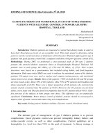
Abstract
English:
The dehydration is an important process in offshore gas processing. The gas is dehy-
drated offshore to avoid dangers associated with pipeline transport and processing of
wet gas. The problems include corrosion, water condensation and plugs created by ice
or gas hydrates.
Thermodynamic simulation of gas dehydration is difficult due to the interaction be-
tween water and glycol. The interaction is due to non-ideal liquid behaviour of water
and glycol mixture. The interaction is impossible to simulate with the normally used
thermodynamic equations of state like Peng-Robinson.
To investigate the problems with the equations of state, the water/glycol mixture is
simulated in MATLAB to investigate the phase behaviour of the mixture. The mixture
is simulated with Peng-Robinson and Peng-Robinson-Stryjek-Vera equation of state.
Peng-Robinson is calculated with both the van der Waals and the Wong-Sandler mixing
rule. The Wong-Sandler mixing rule is used because it incorporates the excess Gibbs
energy and activity coefficient that describes non-ideal liquid behaviour. The MATLAB
simulations were unsuccessful in simulate the water/glycol mixture.
The entire dehydration process has also been simulated in HYSYS, with two thermody-
namic packages. The HYSYS simulation is conducted with the glycol package, which is
created specifically to simulate gas dehydration, and Peng-Robinson. Both thermody-
namic packages are able to simulate the dehydration process, although it can not be de-
termined witch package that gives the most accurate result.
Dansk:
Gas tørring er en vigtig proces i offshore gas behandling. Gas tørres offshore for at und-
gå de farer der er forbundet med rørledningstransport og proces behandling af våd gas.
Disse problemer inkluderer korrosion, vand kondensering og blokering af rør og eller
procesudstyr pga. is eller gas hydrater.
Termodynamisk simulering af gas tørring vanskeliggøres af den vekselvirkning der er
mellem vand og glykol. Vekselvirkningen skyldes at vand og glykol danner en ikke idel
væskeblanding. Denne vekselvirkning er umulig at simulere med de normalt benyttede
termodynamiske tilstandsligninger som Peng-Robinson.
For at undersøge problemet med tilstandsligningerne er vand/glykol blandingen simule-
ret i MATLAB for at undersøge blandingens fase tilstand. Blandingen er simuleret med
Peng-Robinson og Peng-Robinson-Stryjek-Vera tilstandsligningerne. Peng-Robinson er
beregnet med både van der Waals og Wong-Sandler blandingsreglerne. Wong-Sandlers
blandingsregel benyttes fordi den tager højde for Gibbs overskudsenergi og aktivitets
koefficienterne, som beskriver ikke ideel væske blandinger. MATLAB simuleringerne
var ude af stand til at simulere vand/glykol blandingen tilfredsstillende.
Den samlede gas tørrings proces simuleres også i HYSYS, med to forskellige termody-
namiske pakker. HYSYS simuleringerne udføres med glykol pakken, der er speciel ud-
viklet til at simulere gas tørring, og med Peng-Robinson. Begge termodynamiske pakker
kan simulere gas tørrings processen, selvom det ikke kan afgøres hvilken pakke der gi-
ver det mest præcise resultat.
Dan Laudal Christensen Preface K10
Aalborg university Esbjerg 3
Preface
This report is a master thesis in M.Sc.Eng in Chemical Engineering at Aalborg Univer-
sity Esbjerg, under the profile Computational Chemical Engineering.
The project is provided by Atkins Oil and Gas Esbjerg, who has also been helpful with
advice throughout the project
The report is intended for students in chemistry and chemical engineering, and others
with interest in oilfield process engineering and thermodynamic simulation in MAT-
LAB and thermodynamic process simulation in HYSYS. It is thus presumed that the
reader is familiar with chemical and physical terminology.
References are made as [Bx], [Ax], [Wx] and [Ox] in the report, where x represent the
source number and the letters the type of source. B stands for books, A for articles, W
for web pages and O for other. The sources of the references can be seen in section 10.
The articles and other used can be found on the attached CD in the path \SOURCES\.
Figures and tables are marked sequentially in each section of the report. Cross refer-
ences are marked as:
Reference: Refers to:
App. x Appendix x
Figure s.x Figure s.x
Table s.x Table s.x
(s.x) Equation s.x
Where s represents the section number and x again is the number of the reference.
There is a CD attached to the project. This CD contains the project, MATLAB pro-
grams, HYSYS simulations and results and the articles used in this project. Any refer-
ences to the contents on the CD are made to the path where the file is placed. The CD is
inserted between the report and the appendix.
In this report the SI-measuring units are used (with the exception of pressure that are
given in bar and temperature which is in centigrade). Many operation parameters in the
literature are given in oilfield units, if a value from the literature has been converted into
SI-units the original value in oilfield units is given in brackets afterwards e.g. ∆T=5° C
(9° F).
The hydrocarbons in gas and oil are sometime named by there number of carbon atoms,
e.g. C2 that stand for ethane. Some time the hydrocarbons are grouped by there size,
making C2+ ethane and any hydrocarbons larger than ethane.
Gas dehydration
4 Aalborg University Esbjerg
Index
1
INTRODUCTION 6
1.1
O
FFSHORE OIL AND GAS PRODUCTION
6
1.2
P
IPELINE TRANSPORT
6
1.2.1
Water in gas 8
1.2.2
Gas hydrates 9
1.3
P
ROCESSES IN OFFSHORE PRODUCTION
10
1.3.1
Separation 11
1.3.2
Gas treatment 11
1.3.3
Water treatment 13
2
INITIATING PROBLEM 14
3
GAS DEHYDRATION 15
3.1
D
EHYDRATION METHODS
15
3.1.1
Comparison of the methods 16
3.2
W
ATER ABSORPTION
16
3.2.1
Glycols used for dehydration 17
3.2.2
Dry Gas 18
3.3
T
HE GLYCOL DEHYDRATION PROCESS
19
3.3.1
Process description 19
3.3.2
Process plant 23
3.4
P
ART DISCUSSION
/
CONCLUSION
23
4
THERMODYNAMIC 25
4.1
G
ENERAL THEORY
25
4.1.1
Phase equilibrium 25
4.1.2
Excess energy 26
4.2
E
QUATIONS OF
S
TATE
28
4.2.1
Cubic Equations of State 29
4.2.2
Critical Data 29
4.3
P
ENG
-R
OBINSON
E
QUATION OF
S
TATE
30
4.3.1
Multi component systems 30
4.3.2
Phase equilibrium 31
4.3.3
Departures 32
4.4
P
ENG
-R
OBINSON
-S
TRYJEK
-V
ERA
EOS 34
4.5
W
ONG
-S
ANDLER MIXING RULE
34
4.6
P
ART DISCUSSION
/
CONCLUSION
37
5
SIMULATION 39
5.1
MESH
ELEMENTS
39
5.1.1
Material balance 40
5.1.2
Equilibrium 40
5.1.3
Summation 41
5.1.4
Enthalpy 41
5.1.5
Freedom analysis 41
5.2
F
LASH SEPARATION
42
5.2.1
Rachford-Rice 42
5.2.2
Henley-Rosen 44
5.3
S
IMULATION MODEL
46
5.3.1
Input data 46
5.3.2
The MATLAB program 48
5.4
S
IMULATION RESULTS
57
5.4.1
Case 1 57
5.4.2
Case 2 57
5.4.3
Case 3 58
Dan Laudal Christensen Index K10
Aalborg university Esbjerg 5
5.4.4
Case 4 61
5.4.5
Case 5 61
5.4.6
Case 6 62
5.5
P
ART DISCUSSION
/
CONCLUSION
62
6
FINAL AIM 63
7
PROCESS SIMULATION 64
7.1
P
ROCESS SIMULATION PROGRAMS
64
7.1.1
HYSYS 65
7.2
S
IMULATION MODEL
65
7.2.1
Dehydration simulation 65
7.2.2
Dehydration plant specifications 66
7.2.3
Dehydration plant design 67
7.2.4
Creating the simulation model 68
7.3
S
IMULATION RESULTS
71
7.3.1
Case 11 71
7.3.2
Case 12 73
7.4
P
ART DISCUSSION
/
CONCLUSION
74
8
DISCUSSION 75
9
CONCLUSION 76
10
REFERENCES 77
Structure of the report.
Gas dehydration
6 Aalborg University Esbjerg
1 Introduction
The offset for this report is the offshore oil and gas production in the Danish sector in
the North Sea. The specific focus of the report is gas dehydration and the processes in-
volved. This report is therefore introduced with a brief description of the Danish off-
shore sector and offshore processing of reservoir fluid into oil, gas and water. Because
the main focus of the report is gas dehydration, the problems associated with water in
the gas will also be described.
1.1 Offshore oil and gas production
There are two defining characteristics for the Danish offshore production, namely the
shallow water with depths form 35 to 70 m [B1] and that the reservoirs are relatively
thin layers with a limited permeability.
All the platforms in the Danish sector of the North Sea are either production or process
platforms. Because of the low water depth all drilling are preformed with Jack-Up rigs
leased with this specific purpose. This limits the cost of platform construction, because
no space is needed for drilling operations, thus limiting the size of the platform.
Production platforms are either unmanned wellhead platforms or part of a process plat-
form complex. Because of the water depth it is economically viable to install multiple
platforms connected by walkways, or use them as support for bridge modules. The ad-
vantages of platform complexes, consisting of several smaller platforms, are the con-
struction cost and a better safety in case of an emergency situation.
The problem with relative thin reservoirs has been solved with drilling of horizontal
wells. The low reservoir permeability reduces the yield, to increase the yield enhanced
recovery methods are used, primarily by water injection.
[B1]
1.2 Pipeline transport
In the Danish part of the North Sea all the platforms are connected by pipelines. From
the wellhead platforms there are multiphase pipelines to the process platforms. On the
process platforms the reservoir fluid is separated and treated as described in section 1.3.
The oil and gas produced on the platforms is collected before it is exported to shore.
The oil is transported to the Gorm platform; here the oil export pipeline has its origin.
There are two gas pipelines to the Danish shore; they start from Tyra East and Harald.
There is an additional gas export pipeline on Tyra West; this pipeline is connected to the
Dutch NOGAT pipeline. This enables export of the Danish excess gas production to the
Netherlands. The platforms and pipelines in the Danish sector in the North Sea are illus-
trated in Figure 1-1.
Dan Laudal Christensen 1.Introduction K10
Aalborg university Esbjerg 7
Figure 1-1: The Danish sector of the North Sea [B2].
All the pipelines are regularly cleaned and inspected by pigs. Pigs come in two versions,
one version is used to clean the pipelines by pushing all sediments before it; this type of
pig is illustrated in Figure 1-2.
Gas dehydration
8 Aalborg University Esbjerg
Figure 1-2: Pig used for pipeline cleaning. [W1]
The second type of pig is equipped with measuring instruments; this is used for inspec-
tions of the inside of the pipe. Common for all pigs is that they come in a wide range of
sizes, fitting to the pipe that they are used in. The pig is driven forward by the flow in
the pipeline.
There are several problems concerning pipelines, although similar, the problems are
unique for gas, oil and multiphase flow pipelines. For gas pipelines the main problem is
water in the gas.
1.2.1 Water in gas
Water is a problem in the gas phase, both in gas processing and in pipeline transport.
The main problems with water in gas are:
• Corrosion
• Liquid water formation
• Ice formation
• Hydrate formation
In pipelines where it is known that the gas is wet, the problem can be countered. If it is
known in the design phase the pipeline can be designed with more corrosion resistant
materials or increased material thickness. If the problem occurs during production, the
problem can be minimized by injecting inhibitors into the gas.
In dry gas pipelines the problems ought not to occur, but can occur in case of insuffi-
cient dehydration. If not discovered the problems are more serious here, because the
pipelines are not designed for these conditions. When discovered inhibitors can be
added until adequate dehydration is available again.
Liquid water in the pipeline is a problem, not only concerning liquids in compressors,
but also a problem because the liquid water can create liquid plugs and increase corro-
sion.
Dan Laudal Christensen 1.Introduction K10
Aalborg university Esbjerg 9
Ice formation is only a problem when the temperatures are adequately low for ice to
form. Ice is especially a problem in process equipment and valves, where the ice can
create blockages. Ice are manly a problem in low temperature gas treatment like NGL
recovery and gas liquefaction (see section 1.3.2). When low temperature gas treatment
is utilized ultralow water contents are required, making the requirements for the dehy-
dration process more stringent. Although ice is a problem, gas hydrates are often more
troublesome.
[B3], [B4]
1.2.2 Gas hydrates
Gas hydrates are crystals of natural gas and water which can appear fare above the tem-
perature where ice is formed. Gas hydrates are a caged structure containing a gas mole-
cule like methane, the cage is formed by water through hydrogen bonding, as illustrated
in Figure 1-3. Because the gas hydrate crystals are similar to ice crystals, the problems
with gas hydrates are similar to those with ice, although gas hydrates are more trouble-
some because of the higher formation temperature.
Figure 1-3: Gas hydrate [W2].
Because hydrates can form in pipelines, large amounts of hydrates can be in the gas
simultaneously; this can create plugs in the pipeline. Because of the potentially high
hydrate contents in the gas the blockage can arise within minutes without any prior
warning.
Prevention
Because of the potential dangers from gas hydrates they must be prevented. There are
several methods to prevent gas hydrate formation, they are:
• Gas dehydration
• Raising the temperature
• Reducing the pressure
• Adding inhibitors
Gas dehydration is the most efficient way to prevent hydrate formation, but there may
be practical limitation to the use of dehydration, e.g. one central dehydration unit. Gas
dehydration will be treated further in section 3. If the gas stream can not be dehydrated,
one of the other prevention methods must be used. Raising the temperature of a pipeline
is very impractical, likewise is reducing the pressure, because such a reduction will re-
duce the pipeline flow. The only practical solution is therefore to ad inhibitors to the
gas.
Gas dehydration
10 Aalborg University Esbjerg
Inhibitors
Inhibitors acts as antifreeze in the gas, the usual inhibitors are:
• Alcohols
• Glycols
Methanol and monoethylene glycol (MEG) are the most commonly used inhibitors, low
doses are often injected continuously in pipeline where hydrate formation is a problem.
Higher doses of especially methanol are used temporally to dissolve hydrate plugs.
MEG is more viscous than methanol, but has the advantage of being easier to regenerate
from the gas than methanol, because methanol regeneration is usually not feasible.
MEG is the most commonly used glycol, because it is more efficient at a given mass
concentration than diethylen glycol (DEG). DEG may nevertheless be used as inhibitor
in the pipeline, but only if DEG also is the glycol used in the dehydration process after-
wards. The different glycols are treated more thoroughly in section 3.2.1.
There are other possible inhibiters that prevent hydrate formation they are:
• Salts
• Ammonia
• Monoethanolamine
Salts are very rarely used because of the risk of corrosion and deposits. Ammonia is
corrosive, toxic and can form solid deposits of carbonates obtained with carbon dioxide
and water. Monoethanolamine is only attractive if it after pipe transport is used (and
thereby recovered) for gas sweetening.
[B3], [B4]
1.3 Processes in offshore production
On the process platforms the main purpose is to process the reservoir fluid into oil, gas
and water. This has to be done in such a manor that oil, gas and water meets the re-
quirements before oil and gas can be exported and the water released into the sea.
Demands on oil may be the vapour pressure, to insure that no vapour is produced in the
pipeline during transport to shore. Likewise a demand for gas may be no water dew in
the pipeline; other gas demands may be the methane contents or heating value. For the
oil and gas it is also a demand that the pipeline pressure is reached, before it can be ex-
ported from the platform. Water is a by-product, which needs to be cleaned before it can
be disposed off.
To divide the reservoir fluid and insure that the requirements for the three phases are
meet the reservoir fluid is processed. The process equipment can be divided into three
parts.
1. Separation, including oil treatment and export
2. Gas treatment, including gas export
3. Water purification
The processes associated with these three systems may differ for different composition
of reservoir fluid, especially for the gas treatment.
Dan Laudal Christensen 1.Introduction K10
Aalborg university Esbjerg 11
1.3.1 Separation
The first task when the reservoir fluid enters the process equipment is to separate it into
its three phases. This is done in a series of three-phase separators, the number of which
depends upon the inlet pressure of the reservoir fluid.
The first separator divides the reservoir fluid into its three phases. Subsequent separa-
tors are used to improve the purity of the oil and increase the gas recovery. When the
first separation is completed there will still be gas dissolved in the oil, and probably also
some water if the retention time is too small to ensure total separation between the two
liquid phases.
Before the next separation, the pressure of the oil is lowered; this releases more of the
dissolved gas. In case of additional water this will be separated off in the subsequent
separators. This continues until the oil has the required purity, often two or three separa-
tors are enough. When the quality is as desired it is pumped to the pipeline pressure,
before it is exported of the platform and to shore.
The gas released from the oil in the subsequent separators needs to be recompressed
before it can be send to the gas treatment system. Figure 1-4 illustrates a separation sys-
tem with two separators and gas recompression.
Figure 1-4: Separation and oil export
When gas is compressed, it is necessary to cool the gas and separate off any condensed
liquid. In case of more separators than in Figure 1-4, each new separator will also be
equipped with a compressor.
There will also be some liquid recycled from the gas treatment and the water purifica-
tion system, but these streams have been excluded here for simplicity.
[B5]
1.3.2 Gas treatment
The purpose of gas treatment is to clean the gas for unwanted impurities and get it to the
desired condition before it is exported. The composition of the gas is the decisive factor
for which gas treatment procedures that are used. The most common cleaning proce-
dures are gas sweetening, dehydration and hydrocarbon recovery; more seldom treat-
Gas dehydration
12 Aalborg University Esbjerg
ments can be removal of inorganic elements. The purpose of cleaning the gas of its im-
purities is to improve the gas quality, avoid dangers to the process plant or pipeline
from e.g. corrosion or enable the gas to be brought to the desired export condition.
After purification usually only compression is required, for the gas to reach its desired
export condition. In rare cases the desired export condition could require liquefaction of
the gas.
Gas sweetening
To minimize corrosion it is often necessary to remove acid components in the gas. It is
manly CO
2
and H
2
S that are removed, although in some cases other sulphur components
are present in the gas and must therefore also be removed.
The most common sweetening procedure is absorption of the acid, with amines in an
aqueous solution. Afterwards the rich amine solution is regenerated before it can be
reused. Because the amines are in an aqueous solution, the sweet gas will be water satu-
rated. Amine sweetening must therefore be conducted before gas dehydration.
Absorption is the most common procedure, but other procedures can also be used. E.g.
membrane processes if only carbon dioxide are to be removed.
Dehydration
The problems with wet gas have already been described in section 1.2.1, where dehy-
dration was deemed to be the most efficient way to solve the problems associated with
wet gas. Dehydration is usually done by absorption, although other processes like ad-
sorption, membrane processes and refrigeration may be used. The dehydration process
will be described in section 3.
Hydrocarbon recovery
In gas with a high content of C2+ components, there is a risk of NGL (Natural Gas Liq-
uids) formation. NGL may be removed from the gas to avoid liquid in the pipeline or to
sell the more expensive NGL separately, instead of as a part of the gas.
Hydrocarbon recovery is preformed by cooling the gas below its dew point temperature,
condensing the more heavy hydrocarbons in the gas, the condensed liquid is then re-
moved in a separator. The easiest way to cool the gas is in heat exchangers; this is most
efficient at high pressure.
Hydrocarbon recovery by cooling with heat exchangers may not yield the desired gas
purity depending on the initial composition. In these cases the temperature can be low-
ered further by flashing the gas in a Jules-Thompson valve or in a turbo-expander. Be-
cause of the low temperatures achieved by flashing the gas, low water content is essen-
tial to prevent ice formation. Further improvements in hydrocarbon recovery can be
achieved by distilling the liquid from the NGL recovery, thus recovering the methane
condensed in this treatment.
Inorganic contents
If the gas quality is below pipeline quality because of contamination by inorganic ele-
ments, it is necessary to remove these impurities. Some of the inorganic components are
only present in trace amounts, but can none the less create problems.
The most common inorganic component is nitrogen, the nitrogen contents might be
high, either naturally or if nitrogen is used for injection into the reservoir to improve
Dan Laudal Christensen 1.Introduction K10
Aalborg university Esbjerg 13
hydrocarbon recovery. Nitrogen can be recovered by cryogenic distillation, adsorption
or membrane separation.
Radon may be present in the gas, it is radioactive, but with a half-life of 3.8 days the
health problems from radon is minimal. The problem is that it decays into radioactive
lead, which eventually will turn into non-radioactive lead. The result is that low-level
radioactive materials will sediment in the process equipment and pipes; this constitutes
a problem because cleaning produces radioactive waste.
Other contaminants
Benzene, Toluene, Ethylbenzene and Xylene (BTEX) are a problem because of envi-
ronmental concerns. BTEX is removed from the gas during glycol dehydration, a
smaller amount BTEX may also be removed during gas sweetening. When the glycol is
regenerated the BTEX will be removed with the water, and thereby be vented to the
atmosphere. BTEX are also a problem in cryogenic gas treatment because they can
freeze like water.
BTEX can not be removed from the gas before the dehydration. The BTEX problem can
be reduced by using a light glycol, because BTEX is more solvable in larger glycols.
Alternatively the vented gas from the glycol regenerator can be flared or treated to re-
move the BTEX before it is vented to the atmosphere
Compression
The gas is compressed from the process pressure to the pipeline pressure in one or more
steps, depending on the pressure difference. After each compression the gas is cooled
and condensed liquids are separated off.
Liquefaction of the gas
Liquefied natural gas is an advantage when gas is stored or transported by non pipeline
transport. Liquefaction of methane requires extensive refrigeration to temperatures as
low as -161 °C (-258 °F). A very low water contents are therefore required.
[B3], [B4]
1.3.3 Water treatment
Unlike oil and gas treatment, water treatment is an environmental issue. Water is a
waste product in oil and gas production; therefore it is released into the sea or used for
well injection.
When water is separated off in the three-phase separation it still has a small hydrocar-
bon contents. This hydrocarbon contents constitutes no problem when the water is used
for well injection, only when it is released into the sea. Because of environmental con-
cerns the hydrocarbons needs to be removed from the water so the contents is below the
threshold limit value for water released into the sea.
The hydrocarbons in the water are oil that did not separate off in the separators and dis-
solved gas. First the oil is removed using hydrocyclones; the oil is lead back to the sepa-
rator system. The gas is removed from the water by decreasing the pressure thus de-
creasing the solvability in the water. The gas is separated off before the water is released
into the sea.
Gas dehydration
14 Aalborg University Esbjerg
2 Initiating problem
Removing the water from the gas offshore is essentially because it decreases the prob-
lems associated with water in the gas. This makes the dehydration process an essential
part of the offshore gas treatment.
The first step in simulating a dehydration unit is investigating the process design. The
next step is the simulation; the simulation is calculated with thermodynamic equations.
The thermodynamic equations are originally created for non-polar components like hy-
drocarbons. The main part of simulation of the dehydration process is calculating the
water/glycol interaction. Because of this mixtures complex nature, more specific ther-
modynamic equations that can describe the interaction must be used. This has resulted
in the initiating problem:
What problems exist in thermodynamic
simulation of gas dehydration with glycols?
To answer this problem nine other questions have been formulated, the answer of these
will help to clarify some of the aspects associated with the initiating problem.
• What methods exist for gas dehydration?
• Why is glycol dehydration the preferred dehydration process?
• What requirements are given for the dehydration process?
• What processes are involved in the glycol dehydration process?
• What is the thermodynamic theory used in process simulation?
• What thermodynamic equations are used in process simulation?
• What is required to simulate the water/glycol mixture thermodynamically?
• What is required in process simulation calculations in addition to the thermody-
namic equations?
• What is the result of simple phase equilibrium calculations of the water/glycol
mixture?
The main focus of the initiating question and the subquestions is the simulation aspects
of the dehydration process. The project is therefore limited to cover only this aspect of
the dehydration process. Associated aspects like process safety, energy consumption
and similar is out side the scope of this report.
Dan Laudal Christensen 3.Gas dehydration K10
Aalborg university Esbjerg 15
3 Gas dehydration
There are four methods that are used for gas dehydration; they vary in efficiency and
cost.
3.1 Dehydration methods
The methods used for gas dehydration are absorption, adsorption, membrane processes
and refrigeration. The methods may be used by themselves or be combined to reach the
desired water contents.
In dehydration by absorption water is removed by a liquid with strong affinity for water,
glycols being the most common. The lean (dry) glycol removes the water from the gas
in an absorption column known as a contactor. After the contactor the rich (wet) glycol
must be regenerated before it can be reused in the contactor. The regeneration is done
by distilling the glycol thus removing the water. With glycol absorption it is possible to
lower the water contents down to approximately 10 ppm
vol
, depending on the purity of
the lean glycol [B4]. Gas dehydration by glycol absorption will be treated more thor-
oughly in section 3.3.
Dehydration by adsorption is done with a two bed system, where the beds are filled with
adsorbents e.g. silica gel. The gas is lead through one of the adsorbers, where water is
removed. Meanwhile the other adsorber is regenerated by blowing hot dry gas through
it, this gas is then cooled and the water condenses. The Water is separated off and the
gas is lead back to the wet gas, this is illustrated in Figure 3-1.
Figure 3-1: Gas dehydration by adsorption. [B4]
The efficiency of the adsorption process depends on the adsorbent used; there are sev-
eral types of adsorbents available. The most efficient adsorbents are molecular sieves,
this is aluminosilicates that have been altered to improve the adsorption characteristics,
achieving a water contents as low as below 0.1 ppm
vol
[B4].
Gas dehydration
16 Aalborg University Esbjerg
In membrane processes the gas passes through a membrane that separates of the water.
Membrane processes yields water content between 20-100 ppm
vol
[B4]. The problem
with membrane processes are that they only become economically viable compared to
glycol absorption at flows below 1.5·10
6
Nm
3
/d (56 MMscfd) [B4].
Gas dehydration by refrigeration is a low cost dehydration method. Water condenses
when the gas is cooled; the water is then removed in a separator. The separation method
can be conducted numerous times. The method is most efficient at high pressure. The
amount of water removed in the refrigeration process is often insufficient. Because of
the low cost the refrigeration process are often used before the other dehydration proc-
esses.
3.1.1 Comparison of the methods
The two most efficient dehydration methods are absorption and adsorption. Absorption
with glycol is the preferred dehydration method because it is more economical than ad-
sorption. This is due to the following differences between absorption and adsorption:
• Adsorbent is more expensive than glycol.
• It requires more energy to regenerate adsorbent than glycol.
• Replacing glycol is much cheaper than replacing an adsorption bed.
• Glycol can be changed continuously, while changing an adsorption bed requires
a shutdown.
Some low temperature treatment like liquefaction requires water content below what
glycol plants can achieve. In these cases an adsorption plant is required, to minimize the
cost this can be combined with a glycol plant that removes the majority of the water.
[B3], [B4]
3.2 Water absorption
The basis for gas dehydration by absorption is the absorbent; there are certain require-
ments for absorbents for gas dehydration:
• Strong affinity for water to minimize the required amount of absorbent.
• Low affinity for hydrocarbons to minimize hydrocarbon loss during dehydration.
• Low volatility at the absorption temperature to minimize vaporization losses.
• Low solubility in hydrocarbons, to minimize losses during absorption.
• Low tendency to foam and emulsify, to avoid reduction in gas handling capacity and
minimize losses during absorption and regeneration.
• Low viscosity for ease of pumping and good contact between the gas and liquid
phases.
• Large difference in volatility and boiling point compared to water to minimize va-
porization losses during regeneration.
• Good thermal stability to prevent decomposition during regeneration.
• Low potential for corrosion.
Dan Laudal Christensen 3.Gas dehydration K10
Aalborg university Esbjerg 17
The most critical property for a good dehydrator is off course the high affinity for water.
The other criteria are used to evaluate potential absorbents practical applicability in the
industry. In practice glycols are the most commonly used absorbents for dehydration.
3.2.1 Glycols used for dehydration
Glycol is a common name for diols; with the two alcohols these substances have a high
affinity for water. In dehydration 1,2-ethandiol also known as Monoethylen glycol
(MEG) and the small polymers of MEG (diethylen glycol (DEG), triethylen glycol
(TEG) and tetraethylen glycol (TREG)) are the most commonly used for absorbents.
Higher polymers than TREG is usually not used for dehydration because they become
too viscous compared to the smaller polymers.
Properties for MEG, DEG, TEG, TREG and water are compared in Table 3-1.
Table 3-1: Properties for MEG, DEG, TEG, TREG [B3], [B4] and water [B6].
MEG DEG TEG TREG Water
Formula C
2
H
6
O
2
C
4
H
10
O
3
C
6
H
14
O
4
C
8
H
18
O
5
H
2
O
Molar mass [kg/kmol] 62.07 106.12 150.17 194.23 18.015
Normal boiling point [°C] 197.1 245.3 288.0 329.7 100.0
Vapor pressure @ 25 °C [Pa] 12.24 0.27 0.05
0.007
3170
Density @ 25 °C [kg/m
3
] 1110 1115 1122 1122 55.56
Viscosity @ 25 °C [cP] 17.71 30.21 36.73 42.71 0.894
Viscosity @ 60 °C [cP] 5.22 7.87 9.89 10.63 0.469
Maximum recommended regenera-
tion temperature [°C]
163 177 204 224 -
Onset of decomposition [°C] - 240 240 240 -
In Table 3-1 the important values are the normal boiling point, vapor pressure, viscos-
ity, maximum recommended regeneration temperature and the onset of decomposition.
The normal boiling point and vapor pressure has an influence in the distillation. The
greater the difference for these properties between the top and bottom product, the eas-
ier it is to separate the components. The separation between glycol and water is impor-
tant because the water contents in the lean glycol determine the amount of water the
glycol can remove from the gas.
The larger polymers TEG and TREG have the best properties for dehydration. TREG
has slightly better properties than TEG, but because of the additional cost of TREG,
TEG offers the best cost/benefit compromise and is therefore the most commonly used
glycol. [B3]
The decomposition temperature is the point where DEG, TEG and TREG begin to react
with the water and decompose into MEG. The temperatures in [B4] (240 °C) originates
from manufacturer data, but there are some doubts about these temperatures, because
[B4] also give this temperature for TEG as 196 °C, and as 207 °C (404 °F) in [B5].
These temperatures are just below and above the maximum recommended regeneration
temperature of 204 °C (400 °F), which is given in [B3], [B4], [B5] and [B7]. This indi-
cates that some TEG will decompose at 204 °C. At this temperature there will be some
hot-spots in the boiler where the temperature will exceed 207 °C.
Gas dehydration
18 Aalborg University Esbjerg
When TEG decomposes it becomes MEG and DEG, therefore it will not influence the
dehydration process, only give a slightly larger glycol loss because MEG and DEG are
more volatile than TEG.
[B3], [B4], [B5], [B7]
3.2.2 Dry Gas
The efficiency of the dehydration is measured on the water contents in the dry gas. The
dew-point temperature for the water in the gas is often a more useful parameter than the
total water contents. The dew-point temperature must be below the minimum pipeline
temperature, to avoid liquid in the gas pipeline. Figure 3-2 shows the relation between
dew-point temperature and the water contents in the lean TEG at different temperatures.
Figure 3-2: Water dew-point, after dehydration with TEG. [B3]
A dew-point temperature of 6 to 11 °C (10 to 20 °F) below the desired dew-point may
be used to insure against non-ideal situations.
The water dew-point may differ from the gas dew-point; the total gas dew-point may be
influenced by other hydrocarbons in the gas. This can result in condensation of hydro-
Dan Laudal Christensen 3.Gas dehydration K10
Aalborg university Esbjerg 19
carbons in the gas pipeline; this is also undesirable but much less so than water conden-
sation.
[B3], [B4], [B5], [B7]
3.3 The glycol dehydration process
The dehydration process can be divided into two parts, gas dehydration and glycol re-
generation. In dehydration water is removed from the gas using glycol and in regenera-
tion water is removed from the glycol, before it can be reused for dehydration.
Dehydration
Dehydration always consists of an inlet scrubber and a contactor. Sometime it might be
preferable to lower the gas inlet temperature before the dehydration, so an inlet cooler
might also be used.
Regeneration
The main function in the glycol regeneration system can be divided into three:
1. Achieve the optimal pressure and temperature conditions for regeneration of the
rich glycol.
2. Glycol regeneration.
3. Readjust glycol temperature and pressure for optimal dehydration conditions in
the contactor.
Besides these three main points there are some additional features to be considered
when designing a dehydration plant.
• Installing a flash separator before the regeneration column. This separator re-
moves the majority of the hydrocarbons in the dissolved in the glycol.
• Filtering the rich glycol if there is solid particles or liquid hydrocarbons in the
glycol
• Integrating the heat exchangers, so the lean glycol is cooled by heading the rich
glycol, thus minimizing the energy consumption.
• Glycol make up to replace the glycol loss, e.g. in a storage tank.
Because of these considerations the design of the regeneration process varies with the
design of the plant. The integration of heat exchangers is especially important, because
this reduces the overall energy consumption of the plant.
3.3.1 Process description
The process is described by the equipment used in the glycol plant.
Inlet cooler
An inlet cooler may be used because dehydration is more efficient at low temperatures.
Another benefit of inlet cooling is that some water (and hydrocarbons) in the gas will
condense, and be removed in the inlet scrubber, instead of in the contactor.
An inlet cooler is used when the inlet gas temperature is higher than the desired tem-
perature in the contactor. It is also a helpful tool in simulation if the temperature in the
contactor needs to be optimized.
Gas dehydration
20 Aalborg University Esbjerg
Inlet scrubber
The inlet scrubber removes free liquid and liquid droplets in the gas, both water and
hydrocarbons. Removing liquid water in the scrubber decreases the amount of water
that has to be removed in the contractor. This decreases the size of the contactor and the
glycol needed in it, to reach the required conditions for the outlet gas. Liquid hydrocar-
bons are also a problem in the contactor because they increase the glycols tendency to
foam, thereby decreasing the contactors efficiency and increasing the glycol loss in the
contractor and from the regeneration system. Another problem is that hydrocarbons can
be accumulated in the glycol polluting it and thereby decreasing the dehydration effi-
ciency.
Contactor
The contactor is the absorption column where the gas is dried by the glycol. The lean
glycol enters at the top of the contactor while the rich glycol is collected at the bottom
of the contactor and sent to regeneration. The wet gas enters the contactor at the bottom,
while the dry gas leaves at the top.
The required water dew-point of the dry gas dictates the lean glycol temperature and
purity. This is illustrated in Figure 3-2. The glycol temperature into the contactor must
be 3 to 11 °C (5 to 20 °F) higher than the gas entering the contactor to minimize hydro-
carbon condensation into the glycol [B4], [B5].
At contactor temperatures below 10 °C (50 °F) TEG becomes too viscous, thus reducing
the column efficiency. The contactor temperature may be as high as 66 °C (150 °F), but
glycol vaporization loss is often deemed unacceptably high above 38 °C (100 °F) [B5].
The glycol flow into the contactor is dictated by the water content in the gas and num-
bers of trays in the column. A usual glycol flow is 0.017 to 0.042 m
3
Lean TEG per kg
water in the gas (2 to 5 gal TEG/lb Water). Contactor columns with four to six trays
usually operate with 0.025 m
3
TEG/kg Water (3 gal/lb), in larger columns with eight or
more trays the flow is usually reduced to 0.017 m
3
/kg (2 gal/lb) [B4], [B5].
Flash valve
After the contactor column the pressure is reduced to the regeneration pressure by a
flash valve. The pressure drop over this valve depends on the pressure in the contactor
and the pressure loss in the pipes and equipment until the regeneration column.
Two places in the system unwanted gas is vented off the system, in the flash separator
and the regenerator. To prevent blowback the pressure in these units must be higher
than where they vent to. The slightly higher pressure also acts as a propellant in trans-
porting the gas from the dehydration system.
Flash separator
It is a good idea to install a separator after the flash valve. Because of the decreased
pressure hydrocarbons absorbed in the glycol will be released.
Without a separator the gas in the glycol will be released together with water in the re-
generator. In the regenerator the water vapour is usually just vented to the atmosphere,
thus increasing the plants emission of hydrocarbons. With a flash separator the hydro-
carbon rich gas, can be used as process gas in the plant.
The pressure in the flash separator must be above the pressure in the system that the gas
is vented too; the separator pressure will therefore differ between plants.
Dan Laudal Christensen 3.Gas dehydration K10
Aalborg university Esbjerg 21
Filters
Filters are only necessary if there is a problem with solid particles or liquid hydrocar-
bons in the glycol.
Solid particles in the glycol accumulate, increasing the wear on the equipment and can
create plugs in heat exchangers. Solid particles can easily be removed with sock filters,
which can be made of cloth fabrics, paper or fibreglass.
Liquid hydrocarbons like condensate and BTEX can be removed from the glycol by
activated carbon filters.
Heat exchangers
The numbers of heat exchangers varies with the design of the process plant. Because of
the large temperature difference between the contactor and regenerator column, rich
glycol needs to be heated while lean glycol must be cooled. With proper design of heat
exchangers between the rich and lean glycol most of the energy can be conserved.
Rich glycol may be heated before and/or after the flash separation. Heating before the
flash separator increases hydrocarbon recovery along with glycol loss. Heating before
the flash separator is preferable if hydrocarbon contents in the rich glycol after the sepa-
ration are too high.
Besides the heat exchangers the glycol is heated in the regenerator boiler. The lean gly-
col temperature may also need to be adjusted before it enters the contactor, this can be
done with the dry gas or a cooler.
Regenerator
The regenerator is a distillation column, where glycol and water is separated. The rich
glycol is preheated in heat exchangers before it is feed to the regenerator column.
At the top of the column is a partly condenser, this provide reflux thus improving the
separation between water and glycol. The condenser also minimizes glycol loss from
the regenerator. The remaining water vapour leaves the condenser and is vented to the
atmosphere. The temperature in the condenser is given as 98.9 °C (210 °F) [B5].
The energy required to separate glycol and water is supplied by the reboiler at the re-
generator column. The reboiler temperature is dictated by the glycol used for the dehy-
dration as described in section 3.2.1. For TEG the recommended maximum temperature
in the reboiler is 204 °C (400 °F). The Lean glycol is taken from the reboiler and is
transferred to a storage tank before it is recycled or is recycled directly from the re-
boiler.
The pressure in the regeneration system is just above atmospheric pressure, this is to
insure that no air can enter the system from the atmospheric vent.
The operating conditions for the regenerator influence the purity of glycol. At 204 °C
TEG yields a lean glycol concentration of 98.6 wt% [B4]. If this purity of glycol is in-
adequate it can be improved by using more advanced regeneration techniques.
Some simple ways to increase the lean glycol purity is to ad a stripping gas to the re-
generator or regenerate by vacuum distillation. Stripping gas can be added to the regen-
erator boiler or in a stripping column after the regenerator column. By adding stripping
gas to the regenerator boiler the TEG purity can be increased up to 99.6 wt% [B5]. Vac-
uum distillation yields TEG purities up to 99.98 wt% [B4].
Gas dehydration
22 Aalborg University Esbjerg
Stripping column
Glycol purities up to 99.9 wt% can be achieved by using a stripping column after the
regenerator [B5]. The stripping gas from the top of the stripping column is routed to the
regenerator boiler, like when stripping without the stripping column.
The stripping gas is usually nitrogen, dry gas or flash gas from the flash separator. The
water can be removed from the stripping gas by cooling it well below waters dew-point.
If hydrocarbon rich gas is used the gas from the regenerator must be dried or used as
process gas.
To achieve 99.9 wt% pure glycol (or 99.6 wt% without the stripping column), the strip-
ping gas flow must be 28.3 Nm
3
gas/m
3
TEG (4 scf gas/gal TEG) [B5].
Cool stripping gas can be used in the stripping column, because the glycol needs to be
cooled after the regenerator. If on the other hand stripping gas is added directly to the
regenerator boiler it might be preferable to preheat the gas, to keep a uniform tempera-
ture in the boiler.
Glycol storage tank
This is an optional instalment that ensures a constant glycol flow to the contactor col-
umn. Because there will be a loss of glycol in the dehydration system, a storage tank
can act a buffer to prevent insufficient glycol flow, and also be used to measure the gly-
col contents in the system.
Glycol circulation pump
Because of the pressure difference between the regenerator and the contactor, the glycol
pressure needs to be increased. This is done with the glycol regeneration pump. The
glycol is cooled below 80 °C before pumping to protect the pump.
[B3], [B4], [B5], [B7]
Dan Laudal Christensen 3.Gas dehydration K10
Aalborg university Esbjerg 23
3.3.2 Process plant
A possible design of a dehydration plant is given in Figure 3-3.
Figure 3-3: Dehydration plant.
The design in Figure 3-3 incorporates most of the units described in section 3.3.1, with
the exception of the stripping column and a glycol storage tank. Dehydration plant de-
sign often differs from the one given in Figure 3-3; it can be the units or integration of
heat exchangers.
[B3], [B4], [B5], [B7]
3.4 Part discussion/conclusion
There are four models for gas dehydration. They are refrigeration, membrane processes,
adsorption and absorption. Refrigeration does in many case not remove enough water
from the gas, it is however often used in combination with the other dehydration meth-
ods. Membrane processes is only economical for small gas flows, which excludes it in
most dehydration cases. The adsorption yields the lowest water contents in the gas, de-
pendent on the adsorbent. Even though the absorption process can not remove as much
water as adsorption it is often the preferred method. This is because it removes suffi-
cient water to reach the required criteria for the dry gas, as well as gives a better
cost/benefit result than the adsorption process. In some cases where low temperature gas
treatment is involved adsorption dehydration is required. In those cases the cost is often
reduced by combining adsorption plant with an absorption plant.
The efficiency of a dehydration process is evaluated by the water contents in the gas
after the dehydration. The water contents after the dehydration is often given as the wa-
ter dew-point, this is to insure that no water will condense in the pipeline. The water