Accelerating Test, Validation and Debug of High Speed Serial Interfaces
Bạn đang xem bản rút gọn của tài liệu. Xem và tải ngay bản đầy đủ của tài liệu tại đây (8.13 MB, 208 trang )
Accelerating Test, Validation and Debug of High
Speed Serial Interfaces
Yongquan Fan · Zeljko Zilic
Accelerating Test, Validation
and Debug of High Speed
Serial Interfaces
123
ISBN 978-90-481-9397-4 e-ISBN 978-90-481-9398-1
DOI 10.1007/978-90-481-9398-1
Springer Dordrecht Heidelberg London New York
Library of Congress Control Number: 2010938288
c
Springer Science+Business Media B.V. 2011
No part of this work may be reproduced, stored in a retrieval system, or transmitted in any form or by
any means, electronic, mechanical, photocopying, microfilming, recording or otherwise, without written
permission from the Publisher, with the exception of any material supplied specifically for the purpose
of being entered and executed on a computer system, for exclusive use by the purchaser of the work.
Printed on acid-free paper
Springer is part of Springer Science+Business Media (www.springer.com)
Dr. Yongquan Fan
High Performance Analog
Texas Instruments
12500 TI Blvd, Dallas, TX 75243
USA
Prof. Zeljko Zilic
Department of Electrical & Computer
Engineering
McGill University
University Street 3480
H3A 2A Montréal, Québec
Canada
3
To Ji Lei
Yongquan
To Kasia, Maria, Ivan Alexander and Pauline Veronica
Zeljko
vii
Acknowledgments
Systems/LSI Corporation and Texas Instruments for providing a good environ-
ment to conduct this research and finish the book. We especially thank Dr. Yi Cai
at LSI for providing longstanding and wise technical advice and co-authoring two
papers, Professor Gordon Roberts at McGill for giving research guidelines, Bill
Kempler and Sam Yingsheng Tung at Texas Instruments for reviewing the manu-
script. A part of the work leading to this book was undertaken while Yongquan
Fan was pursuing first his M. Eng. and then Ph. D. degree at McGill University.
Altera Corporation has provided also a great support throughout the years, from
their devices and intellectual property, to the encouragement and research funding.
Special thanks go to Steve Brown, Fort Blair, Tomasz Czajkowski and David
Mendel.
At Springer Science+Business Media, Mark de Jongh and Cindy Zitter were
always there for us, providing encouragement and cheering the race to the finish
line.
As with the recent book (Generating Hardware Assertion Checkers, Springer
2008) co-written by Marc Boulé and Zeljko Zilic, the cover page art was drawn by
the second author’s children. This time, Maria Zilic took artistic leadership, with
Authors would like to thank our colleagues and friends at McGill University, Agere
Our thanks also go to Liming Fang, Anant Verma, Bill Burchanowski, and San-
deep Kumar for collaborating on a work that led to co-authoring one paper. We
also appreciate the technical support and help from the whole PHY and Storage
team at Agere/LSI, especially from Angshu Bhattacharyya, Joe Martone, John
Kevin Richter, P aul Hua, Tom
Gibson, Kahn Neguen, Bob Hain and Ken Paist.
In addition, we thank the many people who have given valuable advice, feed-
back and help at conferences and various other occasions. Special thanks are ex-
tended to Mohamed Hafed at DFT Microsystems, Takahiro J. Yamaguchi at Ad-
vantest Corporation, Yang Liang at Maxim, Steve Sunter at Logic Vision, Mike Li
at Wavecrest (now at Altera), Xu Fang at Teradyne, Joe Venable, Shu Xia and
truments, Jwo Cheng and Carlo DiGiovanni from GigOptix,
-Samuel Chenard at McGill
Wai Lee at Texas Ins
Minh Tran from Teledyne, Mani Soma at University of Washington, Luo He at
Concordia University, Warren Gross, Kasia Radecka, Atanu Chattopadhyay,
Man-Wah Chiang, Rong Zhang, Milos Prokic and Jean
University
Janney, Suri Basharapandiyan, Bernhard Laschinsky,
Ivan and Pauline Zilic doing their share to together depict the effects of the jittery
clock in an appealing and a surprisingly lucid way.
Last but not least, we would like to thank our whole families for their love and
support over the years. Without their support, it would be impossible to undertake
all the work and finally write the book.
viii Acknowledgments
ix
Table of Contents
1 Introduction 1
1.1 Motivation 1
1.1.1 HSSI Technology Trends 2
1.1.2 Qualification Challenges 5
1.1.3 ATE Perspectives 6
1.2 Contributions 8
1.3 Overview of the Book 9
2 Background 11
2.1 High-Speed Serial Communication 11
2.1.1 HSSI Structure 14
2.1.2 BER Mechanisms 16
2.1.3 Jitter and Noise Impacts to BER 19
2.2 Timing Jitter 21
2.2.1 Jitter Overview 21
2.2.2 Jitter and BER 23
2.2.3 Jitter Testing 26
2.3 Amplitude Noise 28
2.3.1 BER and SNR 28
2.3.2 Simulation and Emulation 33
2.3.3 AWGN Emulation 34
3 Accelerating Receiver Jitter Tolerance Testing on ATE 37
3.1 Introduction 38
3.1.1 Receiver Structure and Characteristics 38
3.1.2 Jitter Tolerance Testing Overview 44
3.1.3 Proposed New Method 47
3.2 Jitter Test Signal Generation 51
3.2.1 Choosing Test Signal Parameters 52
3.2.2 Periodic Jitter Injection 54
3.2.2.1 Creating Jitter-Free Data Signal 55
3.2.2.2 Creating a Digitized Jitter Signal 55
3.2.2.3 Modulating the Data Signal 56
3.2.2.4 Generating Bandwidth Limited Signals 57
3.2.2.5 Downsampling to Get AWG Samples 59
3.2.3 Fractional Sampling 60
3.2.4 Jitter Calibration 61
3.2.5 Random Jitter Control 64
3.3 Receiver Bit Error Monitoring 65
3.3.1 ATE-based Error Detection 66
3.3.2 DFT-based Error Detection 67
3.4 Jitter Tolerance Extrapolation 68
3.4.1 Jitter Tolerance Extrapolation Algorithm 69
3.4.2 Accelerating Jitter Tolerance Characterization 72
3.4.3 Accelerating Jitter Tolerance Compliance Testing 79
3.4.4 Discussion 81
3.5 Other Applications of the New Method 82
3.5.1 Jitter Transfer Characterization 82
3.5.2 CDR Characteristics Analysis 84
4 Transmitter Jitter Extractions on ATE 87
4.1 Introduction 87
4.1.1 Transmitter Jitter Testing Overview 88
4.1.2 Proposed Solution 89
4.2. Test Setup for Data Acquisition 90
4.2.1 Overview of the Test Setup 90
4.2.2 Principles of Clock Settings 91
4.2.3 Test Setting Parameter Calculations 93
4.3. Jitter Extraction 97
4.3.1 Generating Edge Displacement 98
4.3.2 Time Domain Approach 100
4.3.2.1 RJ Extraction 102
4.3.2.2 DJ Extraction 102
4.3.2.3 TJ Calculation 103
4.3.3 Frequency Domain Approach 107
4.3.3.1 RJ Extraction 107
4.3.3.2 DJ Extraction 108
4.3.4 Hybrid Approach 109
4.3.5 Limitations of Each Approach 111
4.4 Experimental Results 112
4.4.1 Bench Correlation 113
4.4.2 Correlating Two RJ Approaches 113
4.4.3 Impact of Test Patterns 115
4.4.4 Impact of the Reference Clock 116
4.4.5 Extending to 6 Gbps Applications 117
4.5 Summary 118
5 Testing HSSIs with or without ATE Instruments 121
5.1 DFT in HSSIs 122
5.1.1 Internal BERT 122
5.1.2 Internal Loopback 123
5.1.3 Other DFT Techniques 124
5.1.4 Limitations of DFTs 125
x Table of Contents
5.2 FPGA-based Bit Error Detection 125
5.2.1 Implementing a Serial BERT 126
5.2.2 Implementing a Parallel BERT 128
5.2.3. HSSI Testing Demonstration 129
5.3 Loopback Testing with Jitter Injection 130
5.3.1 Testing Setup 130
5.3.2 Phase Delay Based jitter Injection 131
5.3.3 Experimental Results 134
5.4 A Versatile HSSI Testing Scheme 137
5.4.1 Major Functions of our Setup 138
5.4.1.1 Testing, Validation and Debugging on ATE 138
5.4.1.2 External Loopback with Jitter Injection 139
5.4.1.3 Other Configurations 140
5.4.2 High Speed Relays 141
5.4.3 Limitations and Further Considerations 146
6 BER Testing Under Noise 149
6.1 AWGN Generation Overview 149
6.1.1 Existing Methods 150
6.1.1.1 CLT Method 150
6.1.1.2 Box-Muller Method 150
6.1.1.3 Mixed Method 151
6.1.1.4 Cellular Automata Based Method 152
6.1.1.5 Analog Method 153
6.1.2 Our Method 153
6.2 Our Implementation 155
6.2.1 Generating Random Variables 155
6.2.1.1 One Bit Random Number Generator 155
6.2.1.2 Multiple-Bit Random Number Generator 158
6.2.2 Gaussian Variable Generation 159
6.2.2.1 Implementing a Single Generator 159
6.2.2.2 Implementing Two Generators 163
6.2.2.3 Accuracy Improvement 164
6.2.3 Statistical Properties of our AGWN Generator 165
6.2.3.1 Q(x) Evaluation 165
6.2.3.2 Kurtosis Value 168
6.3 Baseband Transmission Testing 169
6.3.1 Baseband Signal Formats 169
6.3.2 SNR Setting 171
6.3.3 Testing Setup and Results 172
6.4 Advantages of Our AWGN Generator 17
7 Conclusions 179
xTable of Contents
i
6
Reference 183
Index 193
x Table of Contents
ii
1 Introduction
Abstract This chapter brings out the motivation for our research, together with
the rudimentary background information on high-speed serial interface standards.
The chapter then enumerates the challenges that we are facing in high-speed se-
rial interface testing, validation and debugging, and finally outlines our solutions
to some of the most pressing challenges.
1.1 Motivation
The High Speed Serial Interface (HSSI), which is interchangeably referred to as
Serializer/Deserializer (SerDes) or simply a Transceiver, is a cornerstone of mod-
ern communication, from high-performance communication and computation in-
frastructure, to the desktop computing and increasingly even to consumer elec-
tronics.
As the HSSI data rate reaches a few Giga-bits per second (Gbps) and continues
to increase, the room for its timing deviation, i.e., jitter, is getting tighter and
tighter. To achieve high data rates, sophisticated techniques such as equalization
and pre-compensation have now become common in HSSIs. With the concurrent
increase in design complexity and decrease in the timing budget, the traditional
“Guaranteed by Design” paradigm is not valid anymore. It is hence becoming im-
perative to qualify the tight timing and other specifications in silicon in order to
guarantee the design quality.
The post-silicon qualification usually consists of three processes: validation of
the first set of fabricated devices, characterization of the devices under all settings
across Process, Voltage and Temperature (PVT) corners, and production testing.
Validation emphasizes on verifying complete device functionality, including pa-
rameter values and electrical characteristics.
Because of the increasing design complexity, close to 25% of all design re-
sources at Intel, for example, are now spent on post-silicon validation [20]. Vali-
dation is usually performed in a lab environment, where standard instruments,
such as oscilloscopes, signal generators and logic analyzers are used. The standard
measurement equipment is also referred to as bench equipment, and the validation
and testing approaches based on standard equipment are also referred to as bench
test solutions.
Characterization is the process that is more concentrated on verifying that the
device can work under all settings and can accommodate process variations al-
lowed in manufacturing. Characterization can in principle be done either in the lab
or on Automatic Test Equipment (ATE), and there is a significant push to achieve
Y. Fan, Z. Zilic, Accelerating Test, Validation and Debug of High Speed Serial Interfaces,
DOI 10.1007/978-90-481-9398-1_1, © Springer Science+Business Media B.V. 2011
2 1 Introduction
as much characterization as possible on an ATE, provided that it is economical to
do so, hence the methods that speed up the characterization on production ATE
testers are of great interest.
Production testing determines the pass/fail of each device in a mass production
environment. The test throughput is paramount in production testing because it di-
rectly affects the device cost. ATE is widely used in production because of its high
throughput, but at high clock rates associated with the emerging HSSI devices, the
ATE equipment might be either too costly or not fast enough.
Among all the HSSI parameters that we need to qualify, Bit Error Rate (BER)
and Jitter are the critical ones. BER is the bit error probability of the system, which
shows how well the system works in an end-to-end manner. Jitter is the deviation
of a signal from its ideal timing, and it is the major cause of bit errors in a well-
designed high-speed communication system. It usually is expressed relative to the
clock signal, where such deviations can cause bits to be incorrectly latched. In
data communications, we now usually talk about bit errors caused by jitter. Jitter
specifications are normally defined at 10
-12
BER rates or lower.
It is very challenging and costly to qualify the timing specification mainly for
three reasons:
• ATE has been widely used in production testing because of its high throughput.
However, the increasing demand for more bandwidth is continuously pushing
the data communication rate higher, at a pace faster than the test equipment
evolves; systematic HSSI testing solutions on ATE for data rates above 6 Gbps
are not commercially mature yet [8].
• Cost goals set by the marketplace demand competitive test solutions – testing
needs to be done as fast as possible, while using as inexpensive equipment as
possible; it is infeasible to use traditional lab instruments in a production envi-
ronment because it takes hours or even days to qualify the jitter and BER per-
formance.
• Validating the jitter performance across PVT corners is becoming necessary
with the continuing scale of the process technology, but the validation is very
time-consuming; shortening the validation time (including debugging when
necessary) would directly reduce the time-to-market, which provides great
competitive advantages in gaining profit and market share.
Motivated by the great economic significance in qualifying HSSIs, this research
concentrates on developing HSSI test and characterization methodologies to ad-
dress the above challenges. We aim to qualify HSSIs accurately and cost-
effectively, yet overcoming ATE limitations.
1.1.1 HSSI Technology Trends
With the evolution of information technology during the past few decades, com-
modities such as cell phones and computers have become commonplace. They
1.1 Motivation 3
have made it a reality for people all over the world to share information or com-
municate directly in one way or another. This evolution has caused a drastic in-
crease in the amount of information generated and the number of end users that
need to access the information. As a platform to communicate information, Inter-
net has become the main driver for technology innovation and bandwidth growth.
The key to meeting the increasing demand for bandwidth is the HSSI.
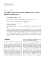
Figure 1-1 illustrates the structure of an Ethernet-based communication infra-
structure. In this network, HSSIs are widely adopted into backplane applications,
short and long-haul communications, mass storage access networking, and com-
puter peripherals. The bandwidth requirement of the HSSIs depends on the prox-
imity to the end-user and the location in the network.
In recent years, different serial communication protocols have arisen to address
a wide set of communication applications, such as Ethernet, XAUI, GPON and
SATA.
Fig. 1-1. HSSIs in communication infrastructure
The HSSI protocols are continuously evolving to higher speeds to meet the
demand for higher bandwidth. One example is the Serial ATA (SATA): when the
SATA 1.0 Working Group was formed in February 2000 to design SATA for
desktops, the target speed was only 1.5Gbps; in 2004 it evolved to 3Gbps and now
SATA 3.0 provides 6Gbps data rate [22]. Another example is the Ethernet:
10Gbps Ethernet (10GbE) was first published by IEEE in 2002 [9]. Currently it is
the fastest matured standard, but IEEE is already in development of 40GbE and
100GbE.
The increasing bandwidth requirements are driving silicon vendors to provide
HSSIs with higher speeds. In 2002, the highest data rate in Altera Field Program-
mable Gate Arrays (FPGAs) was only 1.25 Gbps per channel, available in its
Mercury devices [10]; now in Altera Stratix IV GT FPGAs, the rate has increased
to 11.3 Gbps per channel, with up to 48 transceivers each device [11]. Another
major FPGA provider, Xilinx, provides up to thirty-six 11.2 Gbps transceivers in
its Virtex-6 and Spartan-6 FPGAs, capable of supporting 40G/100G applications
[12].
4 1 Introduction
The increase in data rate and integration in FPGAs is just a snapshot of the
trends in the whole semiconductor industry. Moore’s law is still driving the indus-
try to double the number of transistors in an integrated device every two years,
making it possible to integrate more functions and at the same time provide higher
performance.
The aggressive scaling in deep submicron technologies has enabled the Sys-
tem-on-Chip (SoC) integration of a microcontroller/DSP, ADC/DAC, memory
blocks, power management, PLL and external interfaces. Many Giga-Hertz serial
interfaces are built in SoC type devices with CMOS process. The data rate of the
interfaces also scales accordingly. Besides the FPGA providers, some other semi-
conductor companies have developed HSSIs with data rates up to 10Gbps per
channel, and with up to 100 channels per device [13], [14]. It has been a trend to
put more and faster HSSIs in a single device to meet the increasing bandwidth
demand.
When we keep pushing the speed envelope and increase the integration, many
signal integrity related issues arise, such as timing jitter, noise and frequency loss.
A few key technologies have been developed recently to address these issues [15].
Most notably, the pre-emphasis and equalization techniques are used to compen-
sate frequency-related losses, especially those related to Printed Circuit Board
(PCB) design due to the skin effect and dielectric loss [16].
Pre-emphasis is the process employed in the transmitter to boost the high-
frequency components of a data signal before it is launched to the transmission
medium. Equalization in the receiver acts as a high-pass filter to the data signal
when it enters the receiver and re-shapes the signal in order to interpret the re-
ceived signal correctly.
With the integration increase, there is a trend to implement multiple data rates
in a single HSSI to accommodate multiple protocols. This requires the HSSI capa-
ble of providing multiple rate clock signals. The Phase Locked Loop (PLL) is
widely used for clock generation, where a Voltage-Controlled Oscillator (VCO) is
a key component. There are two types of oscillators: Ring Oscillator (RO) and LC
tank oscillator (LC tank). RO has the advantages of small chip area and wide tun-
able frequency range, but LC tanks provide lower noise and better jitter perform-
ance [17], [18].
Multiple data rates can be implemented by changing divider ratios inside the
PLL or by providing additional VCOs. In Altera Stratix IV GT FPGAs, the RO
can support data rates from 600Mbps to 10.3 Gbps; two LC tanks are also imple-
mented in this device, one with 4.9~6.375 Gbps optimized for PCIe/CEI-6 com-
pliance and the other with 9.9~11.3 Gbps optimized for XLAUI/CAUI/CEI-11G
compliance [19].
A side effect of implementing multiple data rates is that the jitter performance
of the HSSI can vary across its data range. If the same PLL is used at two speeds,
such as 6Gbps and 8.5Gbps, one speed can be susceptible to higher jitter because
the two speeds are derived from the same VCO that can only be optimized at one
speed. If different PLLs are used to support different data rates, the performance at
one data rate does not correlate to another data rate. In either case, good perform-
1.1 Motivation 5
ance at a higher data rate does not guarantee better margin at lower data rates be-
cause PLL characteristics may be different.
1.1.2 Qualification Challenges
With the increasing data rate and higher degree of integration, the staggering
complexity makes it challenging to design fault-free devices. Post-silicon qualifi-
cations are critical in guaranteeing the design quality and the device quality. It is
challenging and expensive to qualify the HSSI devices, especially the jitter per-
formance – transmitter jitter and receiver jitter tolerance.
Numerous HSSI standards define jitter performance at the 10
-12
BER level,
which requires running at least 10
13
bits. This requirement fundamentally limits
the test speed: for instance, at 3Gbps data rate, it takes around one hour to run so
many bits. With some of the emerging applications demanding 10
-14
BER, direct
measurements are even further from being practical.
In addition, many settings in the HSSI may affect its jitter performance. A few
examples include the boost control settings in the equalizer, the bandwidth setting
in the PLL and the driver strength settings in the transmitter. These settings are
quite common in today’s HSSIs. Choosing the optimal setting for the whole HSSI
from hundreds or even thousands of available settings is challenging. It requires a
tremendous amount of resources in validation and test in order to guarantee the
device quality.
Because of the long test time, traditionally the jitter performance of multi-
gigabit HSSI devices is only evaluated on bench in limited combinations of PVT.
Besides the long test time, another reason that jitter is not qualified in production
is the limited availability of ATE instruments, especially for very high-speed ap-
plications. For example, to evaluate 8.5GHz FC devices, we prefer the signal gen-
erator for the receiver and the digitizer for the transmitter with a bandwidth much
higher than 8.5G (such as 15GHz), but they are not commercially mature yet on
ATE [8]. Furthermore, there are currently no systematic ATE solutions that can
perform complete HSSI testing accurately and cost-efficiently. Most companies
only do loopback tests in production to check the functionality. Some HSSI pa-
rameters, such as transmitter jitter and receiver jitter tolerance, are assumed to be
guaranteed by design.
Unfortunately, the “Guaranteed by Design” quality paradigm is no longer valid
while we keep advancing the semiconductor technology and increasing the data
rate, which results in tightening the jitter specifications. The devices can increas-
ingly fail just because they do not comply with the timing specifications. Accord-
ing to the data by Collett International, the timing, mixed-signal interfaces, clock-
ing and crosstalk are among the prime failure reasons, each contributing 18% or
more to the failure of the first silicon.
Since HSSIs uniquely personify all such issues, they are therefore critical to
achieving the overall system quality. It is hence becoming imperative to develop
6 1 Introduction
systematic HSSI compliance testing solutions on ATE to distinguish bad devices
from good ones in production. This is the only way to ensure the device quality
and to eliminate or reduce customer returns.
Since the failures of the first fabricated silicon are now prevalent due to the in-
ability to find the bugs before the fabrication, the post-silicon debugging has be-
come very critical. Here, the goal is to identify the failing cases and perform the
root cause analysis that will detect the real source of the bug. We foresee more
need for HSSI post-silicon debugging and would want to provide the means to fa-
cilitate that in an economical way.
Besides the production testing, ATE is also becoming more and more popular
in characterization and validation due to its high throughput. A thorough valida-
tion and characterization of a design requires performing measurements on differ-
ent process materials at different temperature and voltage combinations. All these
combinations of parameters may lead to measure the same parameter more than
100 times on one device in order to obtain its characteristics under different condi-
tions.
The traditional bench validation approach can no longer meet the requirement
of measuring a large amount of parameters in a short time. ATE-based characteri-
zation and validation solutions therefore have to be employed to meet the re-
quirements.
Our aim in this book is to develop systematic HSSI testing solutions on ATE
that can measure the HSSI standard parameters and design specifications for vali-
dation and characterization purposes. To achieve the best test economy, we as-
sume throughout much of our considerations a simplified test flow in production
that aims to qualify the key parameters only.
1.1.3 ATE Perspectives
In general, ATE can provide high throughput and has been widely used in produc-
tion test. It is also more and more widely use for validation and characterization to
shorten the time-to-market. To validate, characterize and test HSSIs on ATE, there
are several considerations that need to be addressed.
The first concern is the test cost. In early days, HSSI devices were designed as
high-performance and high-margin devices. With the introduction of the low cost
CMOS processes, most of the Gigahertz HSSIs are now built in high-volume and
low-priced SoCs. The large-scale integration makes it however challenging to de-
sign a high performance HSSI block in a very noisy SoC environment. It is then
becoming more challenging to provide competitive production test solution be-
cause of the test time budget.
For an average high-volume SoC, the normal acceptable test time ranges from a
few seconds to ten seconds. The HSSI testing is tied with the testing of all other
analog and digital blocks in the SoC. As one of many blocks in an SoC, it is ex-
pected that the HSSI block testing can be done within 1~2 seconds. For transmitter
1.1 Motivation 7
jitter testing and the receiver jitter tolerance testing, the test time budget is usually
limited to a few tens or hundreds milliseconds because there are hundreds of other
parameters to test. Test cost control is one of the biggest challenges in a mass-
production environment. It is hence urgent to develop jitter testing techniques that
can meet the cost requirement.
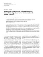
Fig. 1-2. High speed serial interface technology trend
The second major concern is the availability of high-speed instruments on an
ATE tester. The increasing bandwidth demand has been pushing the HSSI data
rate higher and higher. Figure 1-2 illustrates the historic technology points and fu-
ture trends [8].
During the past ten years, the data rate has increased from around 1Gbps to the
10 Gbps range. The HSSI I/O frequency is growing faster than the packaging and
test fixture technology. Because of the physical limits due to the packaging and
test socket, the data rate may slow down somewhat beyond 13 Gbps, shown as the
technology leverage point in Figure 1-2 [8]. During the past few years, the ATE
industry has made significant progress in providing HSSI test solutions. We note
that several ATE suppliers have provided production pin-card solutions up to
6Gbps.
For higher speed, such as 8.5Gbps and 10Gbps applications, systematic ATE
production solutions with jitter testing are not commercially mature yet. Normally,
only loopback testing is implemented in production to provide limited coverage. It
is therefore imperative to address the ATE limitations in order to provide system-
atic production test solutions for applications above 6Gbps. Another ATE limita-
tion is in multi-lane HSSI testing; most ATE platforms do not have enough high-
speed instruments to accommodate the testing of multi-lane HSSI devices.
The third challenge is jitter decomposition and jitter injection. Many modern
HSSI standards specify the jitter specifications in term of Deterministic Jitter (DJ)
and Random Jitter (RJ), so the procedures for testing, characterization and valida-
tion as well need to be cognizant of such types of jitter.
8 1 Introduction
In practice, the traditional concept of histogram based peak-to-peak jitter has
been replaced the by the concept of Total Jitter (TJ), which is related to a certain
BER level. Jitter test solutions need to be capable of decomposing TJ to DJ and
RJ. In addition, uncorrelated jitter detection is also needed because it can fail the
device in real applications but some jitter measurement techniques cannot detect
it.
To conduct a jitter tolerance test for the receiver, we need to have instruments
that can deliberately inject controllable amounts of jitter. Depending on applica-
tions, we may need to inject PJ, RJ or DJ. Integrated ATE instruments that can in-
ject all these kinds of jitter do not exist currently. It is expected that these issues
can be addressed in the test community.
1.2 Contributions
This book addresses the urgent need in the semiconductor industry for cost effi-
cient solutions to qualify HSSI jitter and BER performance [1]. We develop accel-
erated jitter testing solutions based on existing ATE instrument. We also develop
novel low cost, non-ATE solutions that practically overcome the ATE instrument
limitation.
We briefly summarize the contributions of this book as the following set of
goals that we achieved. We:
• Develop a jitter tolerance extrapolation algorithm that can accelerate jitter tol-
erance testing by >1000 times [2]. Based on the algorithm, the book proposes a
solution for jitter tolerance production testing and a solution for characteriza-
tion. Using existing ATE instruments, the production testing only takes a few
tens milliseconds and the characterization only takes around 1 second, the fast-
est solution to the best of our knowledge. Direct measurements down to 10
-12
BER in 3Gbps applications demonstrate the excellent extrapolation accuracy:
the discrepancy between the measured results and extrapolation results is
within 2 ps [3].
• Present solutions for transmitter jitter testing using the time domain, frequency
domain and hybrid approaches based on existing ATE instruments [4]. We
manage to achieve sub-picosecond RJ measurement accuracy: the discrepancy
between the ATE and bench measurement results is within 0.5ps and the run-
to-run variation on ATE is also within 0.5ps. The DJ discrepancy is only a few
pico-seconds. The transmitter jitter testing along with other transmitter testing
can be done in less than 100 milliseconds while existing solutions usually take
a few seconds. In addition, our innovative hybrid approach eliminates some
limitations posed by the time domain and the frequency domain approaches,
making test results more reliable.
• Propose low-cost HSSI testing solutions without the need for employing high-
speed ATE instruments. This is achieved with the following set of sub-goals:
1.3 Overview of the Book 9
o a) Develop a novel jitter injection technique using the state-of-the-art
phase delay lines that can handle clock/data rates of up to 12.5Gbps
[5].
o b) Investigate the applications of high-speed relays and propose a ver-
satile loopback-based jitter compliance testing solution [5].
o c) Develop an FPGA-based BER Tester (BERT) for HSSI bit error
detection [5].
• Besides exploring the jitter impact to BER, the book also addresses the ampli-
tude noise impact on BER. We investigate the digital Gaussian noise genera-
tion and BER testing schemes and propose a novel approach to generate Gaus-
sian noise with excellent tail distribution properties [6].
1.3 Overview of the Book
In the remainder of the book, Chapter 2 presents the background of the research.
We first discuss the HSSI technologies and the BER mechanism. BER is a meas-
ure of the HSSI overall performance. We then introduce how the timing jitter and
the amplitude noise can affect the BER performance.
In Chapter 3, the details of an ATE-based receiver testing solution are pre-
sented. We use a high-speed Arbitrary Waveform Generator (AWG) to generate
test signals with controllable amounts of injected jitter. Based on the calibrated
test signals and the test setup, we develop a jitter tolerance extrapolation algo-
rithm. This algorithm enables us to accelerate the jitter tolerance characterization
and production testing by more than 1000 times. Experimental results demonstrate
the excellent accuracy of the approach.
In Chapter 4, we present the details of an ATE-based transmitter testing solu-
tion. A high bandwidth digitizer is used to capture the transmitter output. We will
introduce how the test settings are developed for data acquisition and how the jit-
ter components are extracted. The proposed solution can complete the transmitter
testing and characterization in100 milliseconds, and the test accuracy reaches sub-
picosecond range.
Chapter 5 discusses the HSSI testing techniques that do not rely on high-speed
ATE instruments. We propose a phase-delay line based jitter injection scheme.
Based on the novel scheme, an external loopback testing solution is developed to
reduce the test cost and also overcome some ATE limitations. By putting the
ATE-based approach and the loopback approach together using high-speed relays,
we propose a more versatile scheme for HSSI validation, debugging, characteriza-
tion and production testing.
In Chapter 6, we address BER testing and debugging under noise conditions.
Traditionally software is used to simulate/evaluate the BER performance of a
communication interfaces under different noise conditions. Even though a soft-
ware based approach is easy to setup, it is too time consuming to perform low
10 1 Introduction
BER evaluation. Hardware based emulation can greatly speed up the evaluation
process. In emulation, a scalable high speed high accuracy Gaussian noise genera-
tor is used to emulate noise conditions. In this chapter, we first survey the current
hardware based Gaussian noise generation techniques, and then propose a novel
approach. Our approach overcomes many limitations of other approaches and is
especially suitable for low BER evaluation.
Conclusions are provided in Chapter 7.
2 Background
Abstract In this chapter, we first introduce the architecture of the HSSI commu-
nication interfaces, together with its common applications. Then, the bit error rate
(BER) mechanisms are explained, and the jitter phenomenon is dealt with in de-
tail. Introduced are the relevant probabilistic properties and the basics of the
simulation and emulation approaches to the modeling of BER effects.
2.1 High-Speed Serial Communication
The high-speed serial communication interfaces have been widely used in modern
communication to deliver fast and robust data transmission. They deliver data at
rates from a few Gigabits per seconds to more than 10 Gbps. Traditional single-
ended I/O standards, such as in PCI and VME, has by now made way to HSSIs, as
they were limited to clock rates of about 200 Mbps due to the combination of
noise and loading (fanout) limitations. Differential I/O standards have been used
to break the frequency barrier of single-ended I/O standards with common mode
rejection. They allow data transmission at higher speeds, although the clock skew
issue arises for differential I/O standards when the frequency approaches 1 Gbps
and beyond [142].
The technology that enables multiple Gbps high-speed serial communication is
often referred to as Clock Data Recovery (CDR). The clock skew concerns are
removed by encoding the clock into every data stream, so CDR circuitry provides
a mechanism for the clock to track the data. Hence, it eliminates frequency barri-
ers faced by clock synchronous systems. Figure 2-1 illustrates the CDR mecha-
nism: a transmitter embeds the clock in the data stream and a receiver employs
specialized CDR circuitry to recover the data, as well as the clock. While this re-
covery circuit is often used to name the whole communication system as a CDR,
in this book, we prefer to refer to such a system as HSSI, as CDR block is just a
part of the receiver.
Y. Fan, Z. Zilic, Accelerating Test, Validation and Debug of High Speed Serial Interfaces,
DOI 10.1007/978-90-481-9398-1_2, © Springer Science+Business Media B.V. 2011