Product design for manufacture assembly geoffrey boothroyd, winston knight, peter Dewhurs(BookZZ org)
Bạn đang xem bản rút gọn của tài liệu. Xem và tải ngay bản đầy đủ của tài liệu tại đây (27.86 MB, 688 trang )
Product
Design
for
Manufacture and Assembly
ISBN:
0-8247-0584-X
This
book
is
printed
on
acid-free
paper.
Headquarters
Marcel
Dekker,
Inc.
270
Madison Avenue,
New
York,
NY
10016
tel:
212-696-9000; fax: 212-685-4540
Eastern Hemisphere Distribution
Marcel Dekker AG
Hutgasse
4,
Postfach
812,
CH-4001
Basel, Switzerland
tel: 41-61-261-8482; fax: 41-61-261-8896
World
Wide
Web
http:
//www.dekker.
com
The
publisher
offers
discounts
on
this book when ordered
in
bulk quantities.
For
more
information,
write to Special Sales/Professional Marketing at the headquarters address
above.
Copyright
©
2002
by
Marcel Dekker, Inc.
All
Rights Reserved.
Neither this book
nor any
part
may be
reproduced
or
transmitted
in any
form
or by any
means, electronic or mechanical, including photocopying, microfilming, and recording, or
by
any
information storage
and
retrieval system, without permission
in
writing
from
the
publisher.
Current printing (last
digit):
10
987654321
PRINTED IN THE UNITED STATES OF AMERICA
MANUFACTURING ENGINEERING
AND
MATERIALS PROCESSING
A
Series
of
Reference
Books
and Textbooks
EDITOR
loan Marinescu
University
of
Toledo
Toledo,
Ohio
FOUNDING
EDITOR
Geoffrey Boothroyd
Boothroyd Dewhurst,
Im
Wa
kefield,
RIi
ode
Island
1.
Computers in Manufacturing,
U.
Rembold, M. Seth, and J.
S.
Weinstein
2.
Cold Rolling of Steel,
William L. Roberts
3.
Strengthening of Ceramics: Treatments, Tests, and Design Applications,
Harry
P.
Kirchner
4.
Metal Forming: The Application of Limit Analysis,
Betzalel Avitzur
5.
Improving Productivity by Classification, Coding, and Data Base Standard-
ization: The Key to Maximizing CAD/CAM and Group Technology,
William
F.
Hyde
6.
Automatic Assembly,
Geoffrey Boothroyd, Corrado
Poli,
and Laurence
E.
Murch
7.
Manufacturing Engineering Processes,
Leo Alting
8. Modern Ceramic Engineering: Properties, Processing, and Use in Design,
David W. Richerson
9.
Interface Technology for Computer-Controlled Manufacturing Processes,
Ulrich Rembold, Karl Armbruster, and Wolfgang Ulzmann
10.
Hot Rolling of Steel,
William L. Roberts
11.
Adhesives in Manufacturing,
edited by Gerald L. Schneberger
12. Understanding the Manufacturing Process: Key to Successful CAD/CAM
I
m pl eme n ta tio n
, Joseph Ha rrington
,
Jr.
13. Industrial Materials Science and Engineering,
edited by Lawrence
E.
Murr
14.
Lubricants and Lubrication in Metalworking Operations,
Elliot
S.
Nachtman
and Serope Kalpakjian
15.
Manufacturing Engineering: An Introduction to the Basic Functions,
John
P.
Tanner
16.
Computer-Integrated Manufacturing Technology and Systems,
Ulrich
Rembold, Christian Blume, and Ruediger Dillman
17.
Connections in Electronic Assemblies,
Anthony J. Bilotta
18. Automation for Press Feed Operations: Applications and Economics,
Edward Walker
19.
Nontraditional Manufacturing Processes,
Gary
F.
Benedict
20.
Programmable Controllers for Factory Automation,
David G. Johnson
21.
Printed Circuit Assembly Manufacturing,
Fred W. Kear
22. Manufacturing High Technology Handbook,
edited by Donatas Tuunelis and
Keith
E.
McKee
23. Factory Information Systems: Design and Implementation for CIM Manage-
ment and Control,
John Gaylord
24. Flat Processing of Steel,
William
L.
Roberts
26. Flexible Manufacturing Systems in Practice: Applications, Design, and
Simulation,
Joseph Talavage and Roger G. Hannam
27. Flexible Manufacturing Systems: Benefits for the Low Inventory Factory,
John
E.
Lenz
28. Fundamentals of Machining and Machine Tools: Second Edition,
Geoffrey
Boothroyd and Winston A. Knight
29. Computer-Automated Process Planning for World-Class Manufacturing,
James Nolen
30. Steel-Rolling Technology: Theory and Practice,
Vladimir B. Ginzburg
31. Computer Integrated Electronics Manufacturing and Testing,
Jack Arabian
32. In-Process Measurement and Control,
Stephan
D.
Murphy
33. Assembly Line Design: Methodology and Applications,
We-Min Chow
34. Robot Technology and Applications,
edited by Ulrich Rembold
35.
Mechanical Deburring and Surface Finishing Technology,
Alfred F. Scheider
36.
Manufacturing Engineering: An Introduction to the Basic Functions, Second
Edition, Revised and Expanded,
John P. Tanner
37.
Assembly Automation and Product Design,
Geoffrey Boothroyd
38. Hybrid Assemblies and Multichip Modules,
Fred W. Kear
39.
High-Quality Steel Rolling: Theory and Practice,
Vladimir B. Ginzburg
40. Manufacturing Engineering Processes: Second Edition, Revised and Ex-
panded,
Leo Alting
41. Metalworking Fluids,
edited by Jerry P. Byers
42. Coordinate Measuring Machines and Systems,
edited
by
John A. Bosch
43. Arc Welding Automation,
Howard B. Cary
44. Facilities Planning and Materials Handling: Methods and Requirements,
Vbay
S.
Sheth
45. Continuous Flow Manufacturing: Quality in Design and Processes,
Pierre C.
Guerindon
46. Laser Materials Processing,
edited by Leonard Migliore
47. Re-Engineering the Manufacturing System: Applying the Theory of Con-
straints,
Robert
€.
Stein
48. Handbook of Manufacturing Engineering,
edited by Jack
M.
Walker
49. Metal Cutting Theory and Practice,
David
A.
Stephenson and John
S.
Agapiou
50.
Manufacturing Process Design and Optimization,
Robert F. Rhyder
51. Statistical Process Control in Manufacturing Practice,
Fred W. Kear
52. Measurement of Geometric Tolerances in Manufacturing,
James
D.
Mea-
dows
53. Machining
of
Ceramics and Composites,
edited by Said Jahanmir,
M.
Rarnulu,
and Philip Koshy
54.
Introduction to Manufacturing Processes and Materials,
Robert C. Creese
55.
Computer-Aided Fixture Design,
Yiming (Kevin) Rong and Yaoxiang
(Stephens) Zhu
56. Understanding and Applying Machine Vision: Second Edition, Revised and
Expanded,
Nello Zuech
57. Flat Rolling Fundamentals,
Vladimir B. Ginzburg and Robert Ballas
58.
Product Design
for
Manufacture and Assembly: Second Edition, Revised and
Expanded,
Geoffrey Boothroyd, Peter Dewhurst, and Winston Knight
Additional Volumes in Preparation
Preface
to the
Second
Edition
This
second
edition
of
Product
Design
for
Manufacture
and
Assembly
includes
three
new
chapters,
describing
the
processes
of
sand
casting,
investment
casting,
and hot
forging.
These
chapters,
combined
with
the
chapters
describing
design
for
machining,
injection
molding,
sheet
metalworking,
die
casting,
and
powder
metals,
cover
a
wide
range
of the
most
basic
forming
processes
used
in
industry.
In
addition,
substantial
material
has
been
added
to the
introductory
chapter
illustrating
the
effects
that
the
application
of
design
for
manufacture
and
assembly
(DFMA)
has had on
U.S.
industry
as a
whole.
Chapter
2,
dealing
with
the
selection
of
materials
and
processes
for
manufacture,
now
includes
further
material
describing
material
selection
specifically
and the
economic
ranking
of
processes
using
a new
software
tool.
Chapter
3,
dealing
with
product
design
for
manual
assembly,
includes
an
updated
special
section
dealing
with
the
effect
of
design
on
product
quality.
Finally,
additional
material
has
been
added
to
Chapter
15
discussing
links
between
computer-aided
design
(CAD)
solid
models
and
design
analysis
tools.
As
with
the
previous
edition,
we
thank
the
various
companies
who
have
supported
research
on
DFMA
at the
University
of
Rhode
Island
and the
graduate
students
who
have
contributed
to the
research.
We
particularly
acknowledge
the
help
of
Allyn
Mackay,
on
whose
work
the new
chapter
on
investment
casting
is
largely
based.
Finally,
thanks
are due to
Shirley
Boothroyd
for
typing
much
of the new
material
and to
Kenneth
Fournier
for
preparing
some
of the
additional
artwork.
Geoffrey
Boothroyd
Peter
Dewhurst
Winston
Knight
\\\
Preface
to the
First
Edition
We
have
been
working
in the
area
of
product
design
for
manufacture
and
assembly
(DFMA)
for
over
twenty
years.
The
methods
that
have
been
developed
have
found
wide
application
in
industry—particularly
U.S.
industry.
In
fact,
it can
be
said
that
the
availability
of
these
methods
has
created
a
revolution
in the
product
design
business
and has
helped
to
break
down
the
barriers
between
design
and
manufacture;
it has
also
allowed
the
development
of
concurrent
or
simultaneous
engineering.
This
book
not
only
summarizes
much
of our
work
on
DFMA,
but
also
provides
the
details
of
DFMA
methods
for
practicing
and
student
engineers.
Much
of the
methodology
involves
analytical
tools
that
allow
designers
and
manufacturing
engineers
to
estimate
the
manufacturing
and
assembly
costs
of a
proposed
product
before
detailed
design
has
taken
place.
Unlike
other
texts
on the
subject,
which
are
generally
descriptive,
this
text
provides
the
basic
equations
and
data
that
allow
manufacturing
and
assembly
cost
estimates
to be
made.
Thus,
for
a
limited
range
of
materials
and
processes
the
engineer
or
student
can
make
cost
estimates
for
real
parts
and
assemblies
and,
therefore,
become
familiar
with
the
details
of the
methods
employed
and the
assumptions
made.
For
practicing
manufacturing
engineers
and
designers,
this
book
is not
meant
as
a
replacement
for the
DFMA
software
developed
by
Boothroyd
Dewhurst,
Inc.,
which
contains
more
elaborate
databases
and
algorithms,
but
rather
provides
a
useful
companion,
allowing
an
understanding
of the
methods
involved.
For
engineering
students,
this
book
is
suitable
as a
text
on
product
design
for
manufacture
and
assembly
and,
in
fact,
is
partially
based
on
notes
for a
two-
course
sequence
developed
by the
authors
at the
University
of
Rhode
Island.
vi
Preface
to the
First
Edition
The
original
work
on
design
for
assembly
was
funded
at the
University
of
Massachusetts
by the
National
Science
Foundation.
Professor
K.
G.
Swift
and Dr.
A. H.
Redford
of the
Universities
of
Hull
and
Salford,
respectively,
collaborated
with
G.
Boothroyd
in
this
early
work
and
were
supported
by the
British
Science
Research
Council.
The
research
continued
at the
University
of
Rhode
Island
and was
supported
mainly
by
U.S.
industry.
We
thank
the
following
companies
for
their
past
and,
in
some
cases,
continuing
support
of the
work:
Allied,
AMP,
Digital
Equipment,
DuPont,
EDS,
Ford,
General
Electric,
General
Motors,
Gillette,
IBM,
Instron,
Loctite,
Motorola,
Navistar,
Westinghouse,
and
Xerox.
We
also
thank
all the
graduate
assistants
and
research
scholars
who
over
the
years
have
contributed
to the
research,
including:
N.
Abbatiello,
A.
Abbot,
A.
Anderson,
J.
Anderson,
T.
Andes,
D.
Archer,
G.
Bakker,
T.
Becker,
C.
Blum,
T.
Bassinger,
K. P.
Brindamour,
R. C.
Burlingame,
T.
Bushman,
J. P.
Cafone,
A.
Carnevale,
M.
Caulfield,
H.
Connelly,
T. J.
Consunji,
C.
Donovan,
J. R.
Donovan,
W A.
Dvorak,
C.
Elko,
B.
Ellison,
M. C.
Fairfield,
J.
Farris,
T. J.
Feenstra,
M. B.
Fein,
R. P.
Field,
T.
Fujita,
A.
Fumo,
A.
Girard,
T. S.
Hammer,
P.
Hardro,
Y.
S. Ho, L. Ho, L. S. Hu, G. D.
Jackson,
J.
John
II, B.
Johnson,
G.
Johnson,
K.
Ketelsleger,
G.
Kobrak,
D.
Kuppurajan,
A.
Lee,
C. C.
Lennartz,
H. C. Ma,
D.
Marlowe,
S.
Naviroj,
N. S.
Ong,
C. A.
Porter,
P.
Radovanovic,
S. C.
Ramamurthy,
B.
Rapoza,
B.
Raucent,
M.
Roe,
L.
Rosario,
M.
Schladenhauffen,
B.
Seth,
C.
Shea,
T.
Shinohara,
J.
Singh,
R.
Stanton,
M.
Stanziano,
G.
Stevens,
A.
Subramani,
B.
Sullivan,
J. H.
Timmins,
E.
Trolio,
R.
Turner,
S. C.
Yang,
Z.
Yoosufani,
J.
Young,
J. C.
Woschenko,
D.
Zenger,
and Y.
Zhang.
We
would
also
like
to
thank
our
colleagues,
the
late
Professor
C.
Reynolds,
who
collaborated
in the
area
of
early
cost
estimating
for
manufactured
parts,
and
Professor
G. A.
Russell,
who
collaborated
in the
area
of
printed
circuit
board
assembly.
Finally,
thanks
are due to
Kenneth
Fournier
for
preparing
much
of the
artwork.
Geoffrey
Boothroyd
Peter
Dewhurst
Winston
Knight
Contents
Preface
to the
Second
Edition
Hi
Preface
to the
First
Edition
v
1.
Introduction
1
1.1
What
Is
Design
for
Manufacture
and
Assembly?
1
1.2
How
Does
DFMA
Work?
8
1.3
Reasons
for Not
Implementing
DFMA
16
1.4
What
Are the
Advantages
of
Applying
DFMA
During
Product
Design?
21
1.5
Typical
DFMA
Case
Studies
22
1.6
Overall
Impact
of
DFMA
on
U.S.
Industry
34
1.7
Conclusions
39
References
40
2.
Selection
of
Materials
and
Processes
43
2.1
Introduction
43
2.2
General
Requirements
for
Early
Materials
and
Process
Selection
45
2.3
Selection
of
Manufacturing
Processes
46
2.4
Process
Capabilities
48
2.5
Selection
of
Materials
55
2.6
Primary
Process/Material
Selection
65
2.7
Systematic
Selection
of
Processes
and
Materials
71
References
83
vii
viii
Contents
3.
Product
Design
for
Manual
Assembly
85
3.1
Introduction
85
3.2
General
Design
Guidelines
for
Manual
Assembly
86
3.3
Development
of the
Systematic
DFA
Methodology
93
3.4
Assembly
Efficiency
93
3.5
Classification
Systems
96
3.6
Effect
of
Part
Symmetry
on
Handling
Time
96
3.7
Effect
of
Part
Thickness
and
Size
on
Handling
Time
101
3.8
Effect
of
Weight
on
Handling
Time
103
3.9
Parts
Requiring
Two
Hands
for
Manipulation
104
3.10
Effects
of
Combinations
of
Factors
104
3.11
Effect
of
Symmetry
for
Parts
that
Severely
Nest
or
Tangle
and May
Require
Tweezers
for
Grasping
and
Manipulation
104
3.12
Effect
of
Chamfer
Design
on
Insertion
Operations
105
3.13
Estimation
of
Insertion
Time
108
3.14
Avoiding
Jams
During
Assembly
109
3.15
Reducing
Disc-Assembly
Problems
111
3.16
Effects
of
Obstructed
Access
and
Restricted
Vision
on
Insertion
of
Threaded
Fasteners
of
Various
Designs
112
3.17
Effects
of
Obstructed
Access
and
Restricted
Vision
on
Pop-Riveting
Operations
115
3.18
Effects
of
Holding
Down
115
3.19
Manual
Assembly
Database
and
Design
Data
Sheets
118
3.20
Application
of the DFA
Methodology
119
3.21
Further
Design
Guidelines
125
3.22
Large
Assemblies
128
3.23
Types
of
Manual
Assembly
Methods
130
3.24
Effect
of
Assembly
Layout
on
Acquisition
Times
133
3.25
Assembly
Quality
137
3.26
Applying
Learning
Curves
to the DFA
Times
141
References
143
4.
Electrical
Connections
and
Wire
Harness
Assembly
147
4.1
Introduction
147
4.2
Wire
or
Cable
Harness
Assembly
149
4.3
Types
of
Electrical
Connections
152
4.4
Types
of
Wires
and
Cables
159
4.5
Preparation
and
Assembly
Times
160
4.6
Analysis
Method
182
References
190
Contents
ix
5.
Design
for
High-Speed
Automatic
Assembly
and
Robot
Assembly
191
5.1
Introduction
191
5.2
Design
of
Parts
for
High-Speed
Feeding
and
Orienting
192
5.3
Example
196
5.4
Additional
Feeding
Difficulties
199
5.5
High-Speed
Automatic
Insertion
199
5.6
Example
201
5.7
Analysis
of an
Assembly
202
5.8
General
Rules
for
Product
Design
for
Automation
203
5.9
Design
of
Parts
for
Feeding
and
Orienting
208
5.10
Summary
of
Design
Rules
for
High-Speed
Automatic
Assembly
210
5.11
Product
Design
for
Robot
Assembly
211
References
217
6.
Printed
Circuit
Board
Design
for
Manufacture
and
Assembly
219
6.1
Introduction
219
6.2
Design
Sequence
for
Printed
Circuit
Boards
220
6.3
Types
of
Printed
Circuit
Boards
220
6.4
Terminology
222
6.5
Assembly
of
Printed
Circuit
Boards
223
6.6
Estimation
of PCB
Assembly
Costs
238
6.7
Case
Studies
in PCB
Assembly
244
6.8
PCB
Manufacturability
249
6.9
Design
Considerations
252
6.10
Glossary
of
Terms
263
References
266
7.
Design
for
Machining
267
7.1
Introduction
267
7.2
Machining
Using
Single-Point
Cutting
Tools
267
7.3
Machining
Using
Multipoint
Tools
275
7.4
Machining
Using
Abrasive
Wheels
284
7.5
Standardization
290
7.6
Choice
of
Work
Material
291
7.7
Shape
of
Work
Material
293
7.8
Machining
Basic
Component
Shapes
294
7.9
Assembly
of
Components
307
7.10
Accuracy
and
Surface
Finish
308
7.11
Summary
of
Design
Guidelines
311
7.12
Cost
Estimating
for
Machined
Components
313
References
337
Contents
8.
Design
for
Injection
Molding
339
8.1
Introduction
339
8.2
Injection
Molding
Materials
340
8.3
The
Molding
Cycle
342
8.4
Injection
Molding
Systems
344
8.5
Injection
Molds
346
8.6
Molding
Machine
Size
351
8.7
Molding
Cycle
Time
353
8.8
Mold
Cost
Estimation
359
8.9
Mold
Cost
Point
System
367
8.10
Estimation
of the
Optimum
Number
of
Cavities
369
8.11
Design
Example
372
8.12
Insert
Molding
374
8.13
Design
Guidelines
375
8.14
Assembly
Techniques
376
References
379
9.
Design
for
Sheet
Metalworking
381
9.1
Introduction
381
9.2
Dedicated
Dies
and
Press-working
383
9.3
Press
Selection
403
9.4
Turret
Pressworking
409
9.5
Press
Brake
Operations
413
9.6
Design
Rules
416
References
422
10.
Design
for Die
Casting
423
10.1
Introduction
423
10.2
Die
Casting
Alloys
423
10.3
The Die
Casting
Cycle
425
10.4
Die
Casting
Machines
426
10.5
Die
Casting
Dies
429
10.6
Finishing
430
10.7
Auxiliary
Equipment
for
Automation
432
10.8
Determination
of the
Optimum
Number
of
Cavities
433
10.9
Determination
of
Appropriate
Machine
Size
439
10.10
Die
Casting
Cycle
Time
Estimation
443
10.11
Die
Cost
Estimation
453
10.12
Assembly
Techniques
457
10.13
Design
Principles
458
References
459
Contents
xi
11.
Design
for
Powder
Metal
Processing
461
11.1
Introduction
461
11.2
Main
Stages
in the
Powder
Metallurgy
Process
463
11.3
Secondary
Manufacturing
Stages
464
11.4
Compaction
Characteristics
of
Powders
468
11.5
Tooling
for
Powder
Compaction
475
11.6
Presses
for
Powder
Compaction
478
11.7
Form
of
Powder
Metal
Parts
481
11.8
Sintering
Equipment
Characteristics
484
11.9
Materials
for
Powder
Metal
Processing
489
11.10
Contributions
to
Basic
Powder
Metallurgy
Manufacturing
Costs
492
11.11
Modifications
for
Infiltrated
Materials
511
11.12
Impregnation,
Heat
Treatment,
Tumbling,
Steam
Treatment,
and
Other
Surface
Treatments
512
11.13
Some
Design
Guidelines
for
Powder
Metal
Parts
514
References
515
12.
Design
for
Sand
Casting
517
12.1
Introduction
517
12.2
Sand
Casting
Alloys
519
12.3
Basic
Characteristics
and
Mold
Preparation
519
12.4
Sand
Cores
524
12.5
Melting
and
Pouring
of
Metal
525
12.6
Cleaning
of
Castings
526
12.7
Cost
Estimating
527
12.8
Design
Rules
for
Sand
Castings
537
12.9
Example
Calculations
542
References
546
13.
Design
for
Investment
Casting
549
13.1
Introduction
549
13.2
Process
Overview
549
13.3
Pattern
Materials
552
13.4
Pattern
Injection
Machines
552
13.5
Pattern
Molds
554
13.6
Pattern
and
Cluster
Assembly
554
13.7
The
Ceramic
Shell-Mold
555
13.8
Ceramic
Cores
556
13.9
Pattern
Meltout
556
13.10
Pattern
Burnout
and
Mold
Firing
557
13.11
Knockout
and
Cleaning
557
xii
Contents
13.12
Cutoff
and
Finishing
557
13.13
Pattern
and
Core
Material
Cost
557
13.14
Wax
Pattern
Injection
Cost
561
13.15
Fill
Time
562
13.16
Cooling
Time
562
13.17
Ejection
and
Reset
Time
564
13.18
Process
Cost
per
Pattern
or
Core
566
13.19
Estimating
Core
Injection
Cost
567
13.20
Pattern
and
Core
Mold
Cost
567
13.21
Core
Mold
Cost
572
13.22
Pattern
and
Cluster
Assembly
Cost
572
13.23
Number
of
Parts
per
Cluster
574
13.24
Pattern
Piece
Cost
575
13.25
Cleaning
and
Etching
576
13.26
Shell
Mold
Material
Cost
576
13.27
Investing
the
Pattern
Cluster
577
13.28
Pattern
Meltout
578
13.29
Burnout,
Sinter,
and
Preheat
578
13.30
Total
Shell
Mold
Cost
579
13.31
Cost
to
Melt
Metal
579
13.32
Raw
Base
Metal
Cost
583
13.33
Ready-to-Pour
Liquid
Metal
Cost
584
13.34
Pouring
Cost
584
13.35
Final
Material
Cost
584
13.36
Breakout
586
13.37
Cleaning
587
13.38
Cutoff
587
13.39
Design
Guidelines
590
References
591
14.
Design
for Hot
Forging
593
14.1
Introduction
593
14.2
Characteristics
of the
Forging
Process
593
14.3
The
Role
of
Flash
in
Forging
595
14.4
Forging
Allowances
600
14.5
Preforming
During
Forging
603
14.6
Flash
Removal
609
14.7
Classification
of
Forgings
610
14.8
Forging
Equipment
613
14.9
Classification
of
Materials
622
14.10
Forging
Costs
622
14.11
Forging
Die
Costs
631
Contents
xiii
14.12
Die
Life
and
Tool
Replacement
Costs
636
14.13
Costs
of
Flash
Removal
637
14.14
Other
Forging
Costs
640
References
641
15.
Design
for
Manufacture
and
Computer-Aided
Design
643
15.1
Introduction
643
15.2
General
Considerations
for
Linking
CAD and
DFMA
Analysis
643
15.3
Geometric
Representation
Schemes
in CAD
Systems
645
15.4
Design
Process
in a
Linked
CAD/DFMA
Environment
660
15.5
Extraction
of
DFMA
Data
from
CAD
System
Database
663
15.6
Expert
Design
and
Cost
Estimating
Procedures
665
References
668
Nomenclature
669
Index
683
1
Introduction
1.1
WHAT
IS
DESIGN
FOR
MANUFACTURE
AND
ASSEMBLY?
In
this
text
we
shall
assume
that
"to
manufacture"
refers
to the
manufacturing
of
the
individual
component
parts
of a
product
or
assembly
and
that
"to
assemble"
refers
to the
addition
or
joining
of
parts
to
form
the
completed product. This
means
that
for the
purposes
of
this
text,
assembly
will
not be
considered
a
manufacturing
process
in the
same
sense
that
machining, molding,
etc.,
are
manufacturing
processes. Hence,
the
term
"design
for
manufacture"
(or
DFM)
means
the
design
for
ease
of
manufacture
of the
collection
of
parts
that
will
form
the
product
after
assembly
and
"design
for
assembly"
(or
DFA)
means
the
design
of the
product
for
ease
of
assembly.
Thus,
"design
for
manufacture
and
assembly"
(DFMA)
is a
combination
of DFA and
DFM.
DFMA
is
used
for
three
main
activities:
1.
As the
basis
for
concurrent
engineering
studies
to
provide
guidance
to the
design
team
in
simplifying
the
product
structure,
to
reduce
manufacturing
and
assembly costs,
and to
quantify
the
improvements.
2.
As a
benchmarking tool
to
study
competitors' products
and
quantify
manufacturing
and
assembly
difficulties.
3.
As a
should-cost
tool
to
help
negotiate
suppliers
contracts.
The
development
of the
original
DFA
method stemmed
from
earlier work
in
the
1960s
on
automatic
handling
[1].
A
group
technology
classification
system
was
developed
to
catalogue
automatic
handling
solutions
for
small
parts
[2].
It
became
apparent
that
the
classification
system
could
also
help
designers
to
design
parts
that
would
be
easy
to
handle
automatically.
1
In
the
mid-1970s
the
U.S.
National
Science
Foundation
(NSF)
awarded
a
substantial
grant
to
extend
this
approach
to the
general
areas
of DFM and
DFA.
Essentially,
this
meant
classifying
product
design
features
that
significantly
effect
assembly
times
and
manufacturing
costs
and
quantifying
these
effects.
At the
same
time,
the
University
of
Salford
in
England
was
awarded
a
government
grant
to
study
product
design
for
automatic
assembly.
As
part
of the
study,
various
designs
of
domestic
gas
flow
meters
were
compared.
These
meters
all
worked
on
the
same
principal
and had the
same
basic
components.
However,
it was
found
that
their
manufacturability
varied
widely
and
that
the
least
manufacturable
design
had six
times
the
labor
content
of the
best
design.
Figure
1.1
shows
five
different
solutions
for the
same
attachment
problem
taken
from
the gas
flow
meters
studied.
It can be
seen
that,
on the
left,
the
simplest
method
for
securing
the
housing
consisted
of a
simple
snap
fit.
In the
examples
on the
right,
not
only
does
the
assembly
time
increase,
but
both
the
number
and
cost
of
parts
increases.
This
illustrates
the two
basic
principles
of
design
for
ease
of
assembly
of a
product:
reduce
the
number
of
assembly
operations
by
reducing
the
number
of
parts
and
make
the
assembly
operations
easier
to
perform.
The DFA
time
standards
for
small
mechanical
products
resulting
from
the
NSF-supported
research
were
first
published
in
handbook
form
in the
late
1970s,
and the
first
successes
resulting
from
the
application
of DFA in
industry
were
reported
in an
article
in
Assembly
Engineering
[3]
.In
the
article,
Sidney
Liebson,
corporate
director
of
manufacturing
for
Xerox
and a
long-time
supporter
of our
research,
suggested
that
"DFA
would
save
his
company
hundreds
of
millions
of
dollars
over
the
next
ten
years."
The
article
generated
intense
interest
in
U.S.
industry.
At
that
time,
microcomputers
were
coming
onto
the
market.
Aversion
of
DFA,
running
on an
Apple
II
plus
computer
proved
attractive
to
those
wishing
to
obtain
the
reported
benefits
of DFA
applications.
It
appeared
that,
unlike
their
European
or
Japanese
counterparts,
U.S.
designers
preferred
to use the new
computers
rather
than
perform
hand
calculations
to
analyze
their
designs
for
ease
of
FIG.
1.1
Examples
of
design
features
affecting
assembly.
assembly.
As a
result,
engineers
at IBM and
Digital
funded
the
development
of
versions
of the DFA
software
to run on
their
own
company
products.
A
major
breakthrough
in DFA
implementation
was
made
in
1988
when
Ford
Motor
Company
reported
that
our DFA
software
had
helped
them
save
billions
of
dollars
on
their
Taurus
line
of
automobiles.
Later,
it was
reported
[4]
that
General
Motors
(GM)
made
comparisons
between
its
assembly
plant
at
Fairfax,
Kansas,
which
made
the
Pontiac
Grand
Prix,
and
Ford's
assembly
plant
for its
Taurus
and
Mercury
Sable
models
near
Atlanta.
GM
found
a
large
productivity
gap and
concluded
that
41% of the gap
could
be
traced
to the
manufacturability
of the two
designs.
For
example,
the
Ford
car had
fewer
parts—10
in its
front
bumper
compared
with
100 in the GM
Pontiac—and
the
Ford
parts
fit
together
more
easily.
Not
surprisingly,
GM has now
become
one of the
leading
users
of
DFMA.
In
fact,
a GM
executive
has
stated
that:
DFM/DEA
is a
primary
driver
of
quality
and
cost
improvement.
It
impacts
every
system
of the
vehicle.
It
is an
integral
part
of
engineering
and
manufacturing
employee
training.
It
provides
knowledge
and
capabilities
for
individuals
and
organizations.
It
provides
technical
improvements
to
both
product
and
process.
It's
not an
option—it's
a
requirement.
In
the
1960s
there
was
much
talk
about
designing
products
so
they
could
be
manufactured
more
easily.
Recommendations
commonly
known
as
producibility
guidelines
were
developed.
Figure
1.2
shows
a
typical
design
guideline
published
in
1971
that
emphasized
simplifying
the
individual
parts
[5].
The
authors
of
this
guideline
mistakenly
assumed
that
several
simple-shaped
parts
are
inherently
less
expensive
to
manufacture
than
a
single
complex
part
and
that
any
assembly
costs
are
more
than
offset
by the
savings
in
part
costs.
They
were
wrong
on
both
counts,
as the
results
in
Tabl e
1.1
show.
Even
ignoring
assembly
costs,
the two
FIG.
1.2
Misleading
producibility
guideline
for the
design
of
sheet
metal
parts.
TABLE
1.1
Estimated
Costs
in
Dollars
for
the Two
Examples
in
Fig.
1.2 if
100,000
Are
Made
Wrong
Right
Setup
Process
Material
Piece
part
Tooling
Total
manufacture
Assembly
Total
0.015
0.535
0.036
0.586
0.092
0.678
0.000
0.678
0.023
0.683
0.025
0.731
0.119
0.850
0.200
1.050
parts
in the
"right"
design
are
significantly
more
expensive
than
the
single
part
in
the
"wrong"
design—even
the
piece part costs (neglecting tooling costs)
are
more
expensive.
Taking assembly costs into account
and
ignoring storage, handling,
quality,
and
paperwork
costs,
the
"right"
design
is 50%
more
costly
than
the
"wrong"
design!
Once
methods
for
analyzing assembly
difficulties
were developed
in the
1970s
it
became recognized that there
was a
conflict
between
producibility
and
assembly.
It was
found
that
the
simplification
of
products
by
reducing
the
number
of
separate parts through
DFA—on
the
order
of 50% on
average—
could
easily achieve substantial reductions
in
assembly costs. Much more
important,
however,
was the
fact
that even greater savings could
be
achieved
in
the
cost
of the
parts.
The
ability
to
estimate
both
assembly
and
part
manufacturing
costs
at the
earliest stages
of
product design
is the
essence
of
DFMA.
The
authors
of
this text have carried
out
numerous research programs over
the
past
two
decades
on the
subject
of
DFMA.
A
primary
objective
of
this work
has
been
to
develop
economic models
of
manufacturing
processes, based
on
product design
information,
and
which
require
a
minimum
of
manufacturing
knowledge
[6,7,8].
The
simple example
in
Fig.
1.2
and
Table
1.1
illustrates this.
If the
"right"
design were
subject
to a DFA
analysis,
the
designer would
be
challenged
as to
why
the
subassembly could
not be
manufactured
as a
single part thereby
eliminating
an
assembly cost
of
$0.20. Further analysis would show
an
additional
saving
of
$0.17
in
part costs.
That
designers should give more attention
to
possible
manufacturing
problems
has
been advocated
for
many
years. Traditionally,
it was
expected that engineer-
ing
students should take
"shop"
courses
in
addition
to
courses
in
machine design.
The
idea
was
that
a
competent designer should
be
familiar
with
manufacturing
processes
to
avoid
adding unnecessarily
to
manufacturing
costs during design.
Unfortunately,
in the
1960s
shop
courses
disappeared
from
university
curricula
in
the
United
States;
they
were
not
considered
suitable
for
academic
credit
by the
new
breed
of
engineering
theoreticians.
In
fact,
a
career
in
design
was not
generally
considered
appropriate
for one
with
an
engineering
degree.
Of
course,
the
word
"design"
has
many
different
meanings.
To
some
it
means
the
aesthetic
design
of a
product
such
as the
external
shape
of a car or the
color,
texture,
and
shape
of the
casing
of a can
opener.
In
fact,
in
some
university
curricula
this
is
what
would
be
meant
by a
course
in
"product
design."
On
the
other
hand,
design
can
mean
establishing
the
basic
parameters
of a
system.
For
example,
before
considering
any
details,
the
design
of a
power
plant
might
mean
establishing
the
characteristics
of the
various
units
such
as
genera-
tors,
pumps,
boilers,
connecting
pipes,
etc.
Yet
another
interpretation
of the
word
"design"
would
be the
detailing
of the
materials,
shapes,
and
tolerance
of the
individual
parts
of a
product.
This
is the
aspect
of
product
design
mainly
considered
in
this
text.
It is an
activity
that
starts
with
sketches
of
parts
and
assemblies;
it
then
progresses
to the CAD
workstation,
where
assembly
drawings
and
detailed
part
drawings
are
produced.
These
drawings
are
then
passed
to the
manufacturing
and
assembly
engineers
whose
job it is to
optimize
the
processes
used
to
produce
the
final
product.
Frequently,
it
is
at
this
stage
that
manufacturing
and
assembly
problems
are
encountered
and
requests
are
made
for
design
changes.
Sometimes
these
design
changes
are
large
in
number
and
result
in
considerable
delays
in the
final
product
release.
In
addition,
the
later
in the
product
design
and
development
cycle
the
changes
occur,
the
more
expensive
they
become.
Therefore,
not
only
is it
important
to
take
manufacture
and
assembly
into
account
during
product
design,
but
also
these
considerations
must
occur
as
early
as
possible
in the
design
cycle.
This
is
illustrated
qualitatively
by the
chart
in
Fig.
1.3
showing
that
extra
time
spent
early
in the
design
process
is
more
than
compensated
for by
savings
in
time
when
prototyping
takes
place.
Thus,
in
addition
to
reducing
product
costs,
the
application
of
design
for
manufacture
and
assembly
(DFMA)
shortens
the
time
to
bring
the
product
to
market.
As an
example,
Ingersoll-Rand
Company
reported
[9]
that
the use of
DFMA
software
from
Boothroyd
Dewhurst,
Inc.,
slashed
product
development
time
from
two
years
to
one.
In
addition,
the
simultaneous
engineering
team
reduced
the
number
of
parts
in a
portable
compressor
radiator
and
oil-cooler
assembly
from
80 to 29,
decreased
the
number
of
fasteners
from
38
to 20,
trimmed
the
number
of
assembly
operations
from
159 to 40 and
reduced
assembly
time
from
18.5
to
6.5min.
Developed
in
June
1989,
the new
design
went
into
full
production
in
February,
1990.
Another
reason
why
careful
consideration
of
manufacture
and
assembly
should
be
considered
early
in the
design
cycle
is
because
it is now
widely
accepted
that
over
70% of
final
product
costs
are
determined
during
design
[10].
This
is
illustrated
in
Fig.
1.4.
FIG.
1.3
DFMA
shortens
the
design
process.
(From
Plastics
Design
Forum,
October
1993.)
FIG.
1.4 Who
casts
the
biggest
shadow?
(From
Ref.
10.)
FIG.
1.5
"Over
the
wall"
design,
historically
the way of
doing
business.
(From
Ref.
10.)
Traditionally,
the
attitude
of
designers
has
been
"we
design
it, you
build
it."
This
has now
been
termed
the
"over-the-wall
approach"
where
the
designer
is
sitting
on one
side
of the
wall
and
throwing
designs
over
the
wall
(Fig. 1.5)
to the
manufacturing
engineers,
who
then
have
to
deal
with
the
various
manufacturing
problems
arising
because
they
were
not
involved
in the
design
effort.
One
means
of
overcoming
this
problem
is to
consult
the
manufacturing
engineers
at the
design
stage.
The
resulting
teamwork
avoids
many
problems.
However,
these
teams,
now
called
simultaneous
engineering
or
concurrent
engineering
teams,
require
analysis
tools
to
help
them
study
proposed
designs
and
evaluate
them
from
the
point
of
view
of
manufacturing
difficulty
and
cost.
By
way of
illustration
we see
that
DFMA
efforts
at
Hewlett
Packard
Loveland
[11]
started
in the
mid-1980s
with
redesign
of
existing
products
and
continued
with
application
to new
product
design.
During
these
studies,
which
proved
increasingly
successful,
product
development
involved
one to
three
manufactur-
ing
engineers
interacting
frequently
with
the R&D
team
members.
Eventually,
by
1992,
HP
Loveland
had
incorporated
DFMA
into
a
formal
concurrent
engineer-
ing
approach.
The
gradual
improvements
in
their
product
manufacturing
and
assembly
costs
are
shown
in
Fig.
1.6.
FIG.
1.6
Effects
of
DFMA
and CE on
product
cost
at
Hewlett
Packard. (Adapted
from
Ref.
11.)
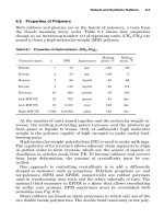
1.2
HOW
DOES
DFMA
WORK?
Let's
follow
an
example
from
the
conceptual
design
stage.
Figure
1.7
represents
a
motor
drive
assembly
that
is
required
to
sense
and
control
its
position
on two
steel
guide
rails.
The
motor
must
be
fully
enclosed
for
aesthetic
reasons
and
have
a
removable
cover
to
provide
access
to
adjustment
of the
position
sensor.
The
principal
requirements
are a
rigid
base
designed
to
slide
up and
down
with
guide
rails
that
will
both
support
the
motor
and
locate
the
sensor.
The
motor
and
sensor
have
wires
connecting
to a
power
supply
and
control
unit,
respectively.
A
proposed
solution
is
shown
in
Fig. 1.8,
where
the
base
is
provided
with
two
bushings
to
provide
suitable
friction
and
wear
characteristics.
The
motor
is
secured
to the
base
with
two
screws
and a
hole
accepts
the
cylindrical
sensor,
which
is
held
in
place
with
a set
screw.
The
motor
base
and
sensor
are the
only
items
necessary
for
operation
of the
device.
To
provide
the
required
covers,
an
end
plate
is
screwed
to two
standoffs,
which
are
screwed
into
the
base.
This
end
plate
is
fitted
with
a
plastic
bushing
through
which
the
connecting
wires
pass.
Finally,
a
box-shaped
cover
slides
over
the
whole
assembly
from
below
the
base
and is
held
in
place
by
four
screws,
two
passing
into
the
base
and two
into
the end
cover.
There
are two
subassemblies,
the
motor
and the
sensor,
which
are
required
items,
and,
in
this
initial
design,
there
are
eight
additional
main
parts
and
nine
screws
making
a
total
of
nineteen
items
to be
assembled.
3.25
'
attached
to
screw
drive
-guide
rails
\\
\\
\\\\\\\A
\
connecting
wires
•*-
nnotor
driven
assembly
inside
cover
controlled
gap
FIG.
1.7
Configuration
of
required
motor
drive
assembly.
When
DFA
began
to be
taken
seriously
in the
early
1980s
and the
consequent
benefits
were
appreciated,
it
became
apparent
that
the
greatest
improvements
arose
from
simplification
of the
product
by
reducing
the
number
of
separate
parts.
In
order
to
give
guidance
to the
designer
in
reducing
the
part
count,
the DFA
methodology
[12]
provides
three
criteria
against
which
each
part
must
be
examined
as it is
added
to the
product
during
assembly.
1.
During
operation
of the
product,
does
the
part
move
relative
to all
other
parts
already
assembled.
Only
gross
motion
should
be
considered—small
motions
that
can be
accommodated
by
integral
elastic
elements,
for
example,
are not
sufficient
for a
positive
answer.
2.
Must
the
part
be of a
different
material
than
or be
isolated
from
all
other
parts
already
assembled?
Only
fundamental
reasons
concerned
with
material
properties
are
acceptable.
3.
Must
the
part
be
separate
from
all
other
parts
already
assembled
because
otherwise
necessary
assembly
or
disassembly
of
other
separate
parts
would
be
impossible.
Application
of
these
criteria
to the
proposed
design
(Fig.
1.8)
during
assembly
would
proceed
as
follows:
1.
Base:
Since
this
is the
first
part
to be
assembled,
there
are no
other
parts
with
which
it can be
combined,
so it is a
theoretically
necessary
part.
COVER
16
gage
I.e.
steel,
painted
soldered
seams
4.5 X
2.75
X 2.4
SET
SCREW
0.06 dia.
X
0.12
COVER
SCREW
(4)
0.12
dia.
X
0.3
END
PLATE
I.e.
steeJ,
painted
4.5x2.25x1.3
BUSH
(2)
brass,
impregnated
powder
metal
0.5
dia.
x
0.8
MOTOR
2.75
dia.
X
4.75
PLASTIC
BUSH
0.7
dia.
x 0.4
MOTOR
SCREW
(2)
0.2
dia.
x 0.6
BASE
aluminum,
machined
4
x 2,2 x 1
SENSOR
0.187
dia.
x1
STAND-OFF
(2)
I.e.
steel,
machined
0.5
dia.
x 2
END
PLATE
SCREW
(2)
-
0.2
dia.
x 0.5
FIG.
1.8
Proposed
design
of
motor
drive
assembly
(dimensions
in
inches).