KẾT CẤU MỚI PRINCIPLES OF CONSTRUCTION FOR WIDESPAN STRUCTURES FROM THE MILLENNIUM DOME
Bạn đang xem bản rút gọn của tài liệu. Xem và tải ngay bản đầy đủ của tài liệu tại đây (2.15 MB, 10 trang )
159
PRINCIPLES
OF
CONSTRUCTION
FOR
WIDE-SPAN
STRUCTURES WITH EXAMPLES
FROM THE MILLENNIUM DOME
Peter W Miller
Watson Steel Limited
SYNOPOSIS
There
are a
number
of key
issues that need
to be
considered
in
planning
the
construction
of any
complicated structure
and the
Millennium Dome
was no
different.
This paper gives
a
brief description
of the
construction
method adapted
for the
Dome
and
then describes
the
major issues that
had to be
dealt with
in the
planning
and
construction
of the
Structural steelwork
and
cable
net
that forms
the
structural framework
for the
Dome.
An
explanation
of the
thought processes leading
to the
eventual construction scheme
is
given
and it
will
be
shown that many
of the
principles described here also
apply
to any
wide-span structure
INTRODUCTION
In late 1996 Watson Steel were invited
to
submit
a
tender
for
the
supply
and
construction
of the
steel
and
cable
frame
for the
Millennium Dome.
In
order
to
begin
to
estimate
the
construction costs
of
such
an
unusual
and
large-scale structure
a
workable
and
economic
construction scheme
had to be
developed.
The
construction scheme produced
at
that time, whilst just
a
series outline sketches,
was
fundamentally
the
same
as
that which
was
eventually used.
A
great amount
of
detailed development post contract award took place
however
and
some
of the
attention
to
detail that
was
required will
be
demonstrated
in the
following pages.
OUTLINE
OF THE
CONSTRUCTION
SCHEME
Each
of
the
12
masts
and the
pyramids that support them
were assembled
and
fully site welded
in an
area adjacent
to
the
permanent site.
The pyramids were carried
to the
site
and
were placed
on
the concrete piled foundations with
a
crawler crane.
The masts were also carried with
the
same crane
and
laid
out adjacent
to
their final position. Whilst there, they
were fitted
out
with
the
temporary erection gear that
was
subsequently used
for the
cable pulling
and
also
had the
restraint cables attached, before being lifted into position
with
a
large
1000
tonne capacity strut jib crane.
WMR/A
Hi
it
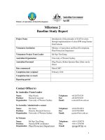
Fig
1 A 90
metere mast
is
reared
up
prior
to
being placed
on
the
pyramid
The masts were guyed
off
with four restraining cables
before
the
crane
was
released.
The
front two
of
the cables
were temporary
but for
the rear two,
the
permanent back-
stay cables, which
ran
directly
to
ground anchors could
be utilised.
In
order
to
restrict
the
movement
of the
masthead under wind loads
the
four restraining cables
were post tensioned
to a
predetermined force
in the
order
of 200KN before
the
crane
was
released. This operation
was further complicated
by the
fact that
the
mast head
position
in
space
was
monitored
and was
required
to be
within 150mm
of
theoretical when
the
stressing
was
completed.
The
mast
was
mounted
on a
rubber bearing
located
on top of the
pyramid which allowed this small
amount
of
rotational movement.
160
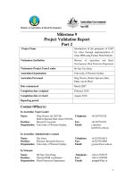
Fig 2 These three sketches show the rearing
procedure for the masts
The cable net, which consisted of over 2600 cables was
assembled and lifted in four main sections. Each section
formed a large concentric circle which when pulled
simultaneously at 36 positions was elevated to its final
height. The missing infill cables between the circular
sections were installed individually using a combination of
abseiling techniques for the higher locations and powered
access equipment where practical.
Fig 3 The second cable net being reared up
with 36 pulling jacks.
When all cables had been installed they were tensioned
to their final design stress by progressively jacking at the
anchor points of the 72 pairs of radial cables. The
stressing operation was carried out in a balanced manner
around the dome in three stages.
The erection of the masts commenced on 15
th
October
1997 and the stressing was completed by the end of
March 1998. A period of only 16 working weeks.
PLANNING
The key to all successful site construction projects is
detailed planning and the more complicated the project
the more important detailed planning becomes.
Inevitably wide-span projects tend to be unique and
challenging where the need for lateral thinking combined
with attention to detail becomes even more important.
On the Dome an internal system for planning and
developing the construction method was established
within Watson's that proved to work very well. This was
based on regular brainstorming sessions where the most
experienced and practical engineers within our business
with both fabrication and erection experience debated
specific topics and put all the ideas on the table. The
project team would go away and examine all the options
and develop the ideas. The project team would then
present their conclusions back to the gathered engineers
for critique. Meetings were held weekly at the outset of
the project when the construction scheme was formed
and thereafter as and when required.
When the options had been narrowed down to a few
options they would all be costed out to determine which
was the most economic.
Fig 4 A full scale trial was carried out on the first
mast section to 'prove' the planned net pulling method
161
Quite often practical trials were required to determine the
best options. When the stage had been reached where the
scheme was finalised on paper it was decided to carry out
a full-scale trial. This was carried out in the Bolton
factory using the first of the mast head sections that was
fabricated in July 1997. This trial proved to be a good
investment.
The outcome of this planning / development stage was a
detailed method statement which was developed
gradually over several months.
PRE-ASSEMBLY
For any construction scheme to be successful it must be: -
a) Safe
b) Economic
c) Fit within programme constraints
d) Comply with specification
One method commonly employed to ensure that these
criteria are met is to pre-assemble as much of the structure at
ground level as possible.
In the case of the Dome this principle was applied to the
pyramids, the main masts and to the erection of the cable net
that forms the structural framework of the Dome and
supports the fabric covering. The final decision on which
elements and to what extent they should be pre-assembled
depends on many factors including cost, availability of large
cranes, programme, height above ground, and the alternative
safe means of man access. In the following paragraphs the
decisions that were taken on the pre-assembly of the
principle elements of the Dome are described.
PRE-ASSEMBLY OF PYRAMIDS
The four-legged pyramids that support the 12 masts are over
8 metres wide and 10 metres high and therefore had to be
constructed on site. The design forces and architectural
requirements meant that site welding of the node joints was
the only feasible option. The overall construction
programme however could not be achieved if the
construction of the pyramids was delayed until the
permanent foundations were available. The solution was to
pre-assembly the pyramids on a temporary foundation in a
separate area away from the main construction zone. The
completed pyramids were then stored and eventually carried
to their permanent location, using a large crane, once the
foundations were released.
The advantage of pre-assembling all the twelve pyramids in
a specific assembly area was that once the assembly jig was
set up and checked it could be used twelve times and all the
pyramids were sure to be identical and therefore
interchangeable. The fact that a large crawler crane in excess
of 200 tonnes nominal capacity was required was not a
disadvantage because the crane was planned to be on site
anyway throughout the period to assemble the mast sections.
Fig 5 One of the completed pyramids being placed
on to the foundations
PRE-ASSEMBLY OF MASTS
It was a fairly obvious solution to build the main 90 metre
masts on the ground and to lift them with a large crane. The
original cross sectional diameter of the masts however was
greater than we could transport on the public roads by
conventional trailers. This would mean that there were either
very expensive transport costs or else only half the mast
cross section was fabricated in the factory and the remaining
fabrication completed on site. Both options were considered
undesirable and following discussions with the Engineers it
was agreed that the overall diameter of the masts could be
reduced in size and the design compensated by increasing
the wall thickness of the eight tubes that made up the
octagonal cross section of the mast.
Fig 6 May 1997 A completed mast section ready for dispatch to
the painters
162
This small structural change had
a
significant effect on the
costs since it was now possible to fabricate the masts almost
entirely within the factory leaving just five joints along the
length to be completed on site in the pre-assembly yard.
Fig
7
A
Fully painted section arrives
in
the site assembly area.
As
in
the case
of
the pyramids described
in
the previous
paragraph, the decision was taken to pre-assemble the masts
away from their permanent location. This was due to the fact
that the foundation works for the masts had to be carried out
in parallel with
the
mast build because
of
the
overall
programme constraints.
The
moving
of
the
completed
masts,
however, which were 90 metres long and weighed 95
tonnes, was
a
much more difficult problem. Various options
were considered and evaluated. These included using special
multi-axial transporters, using a bogey system on a track etc.
The solution which was eventually selected was to pick and
carry the masts with the large 200 tonne capacity crawler
crane. This was only possible
if a
flat and well-compacted
route could be provided and a great deal of investigation was
carried out to select and subsequently prove the route. This
exercise was further complicated because
of
limitations
to
the ground loading pressure that could
be
applied
in
the
region around the Blackwall tunnel that crossed the site.
Fig
8
A full mast being carried from the assembly area on
to the site
PRE-ASSEMBLY OF CABLE NETS
There are over 2600 separate cables that form the 'web'
structure
of the
dome. This presented, perhaps,
the
biggest challenge to the Watson Steel construction team.
The initial objective
in
developing
the
scheme
for
the
installation of the cables was to assemble the complete net at
ground level and lift
it
in to position in one operation. This
would have the massive advantage
of
removing almost all
the risk of the high level work. It is also many times faster to
install a cable in to a net at ground level under zero load, than
it is to install
it
into
a
existing framework of cables at high
level.
This initial objective however was found to be impracticable
and over ambitious
due
to
the
weight,
and the
many
complications, technical difficulties
and
costs that
it
introduced.
It was next considered splitting the net into two sections and
lifting these individually and just mstalling the
72
radial
cables between them at high level. Again
it
was found that
the technical issues were
too
difficult
and
so the
next
preferred option
of
three sections was investigated. This
iterative process was continued until, after much debate, the
eventual decision was
to
opt for the pre-assembly
of
four
separate rings and to complete the infill between these rings
by lifting one cable at
a
time at high level.
This sort
of
compromise
is
necessary
and
indeed often
essential, when developing
any
complicated erection
method. Having
to
satisfy Safety, programme, and budget
considerations inevitably involves compromise.
It was possible using this chosen method to assemble over
75%
of
the
cables
at
ground level under
a
zero load
condition. The difference in terms
of
man-hours between
a
cable laid out on the ground and one installed at high level is
estimated to be at least six-fold. The saving in terms of cost
and time of maximising the pre-assembly of a cable structure
is therefore enormous.
The following figures 9,10,11 show the lifting arrangement
for the first two nets. This was complicated because
the
temporary restraint cables for the masts passed over the top
of the second net where it was pre-assembled on the ground.
The temporary restraint to the masts therefore had to be re-
diverted via the previously erected central cable truss, once
the initial central net was lifted.
Masts
restrained
by
temporary forestays
with first
cable ring ready
for lifting
Fig 9
163
SITE WELDING
NIERNN.
WORMNG
FWFOHM
.MMIfW
JMPowWl
:
\
/IB*OMW\
/\ gwyj ||
' 1HQW'
Central ring
lifted
-
mast restraint
transferred to new tie downs
Figure 10
Temporary forestays
removed
masts now
restrained
by tie downs to central ring
Fig 11
The handling of cables is a key issue that needs careful
consideration. It is very easy to cause accidental damage
during laying out and handling that may necessitate
having to replace the cable. The sequence of the
assembly operation has to be planned in-depth to ensure
that access routes are maintained and that the site
equipment that is being used to handle the cables does
not have to run over previously laid cables. The cables
used on the Dome were of the spiral strand type, which
are highly susceptible to damage caused by kinking or
squashing. And any cables that showed signs of
distortion had to be replaced.
On the Dome, a method for laying out the cables using a
forklift truck and a turntable on a flat wagon was
developed. The cables were delivered in coils of a
standard inside diameter. The coils were placed on a
turntable on the back of a small flat bed wagon. The
loose end of the cable was restrained using the fork lift
truck while the wagon drove slowly away allowing the
cable to unwind on to ground in a predetermined
position. Some of the larger cables which ranged up to
90mm diameter also required auxiliary craneage to assist
in the laying out.
Many engineers tend to avoid site welding wherever
possible. This may be due to preconceptions about
quality, time or cost. In reality site welding can often be
more economic and can provide a better engineering
solution than bolting. The difficulty however is that there
is no golden rule and the only way to determine which is
actually the 'best' method for a particular application is
to carry out a detailed comparison on a job by job basis.
On the Dome, for example, the original specification was
for the mast joints to be site bolted using a pipe flange
detail as it was considered to be the more economic
solution. The architect however preferred a smooth site
welded detail and so an option was included within the
tender for the contractor to specify the 'extra-over' costs
he would require to site weld, grind and paint the 480
joints in-lieu of bolting. When the actual cost of the
options was calculated cost it was cheaper to give the
architect and engineer what they preferred and to site
weld the complete mast! A good example of a win-win
solution!
Fig 12 One of the 480 mast joints being welded on site using a flux
cored wire process.
The reason why site welding is sometimes cheaper is
because it can dramatically simplify the shop fabrication
element of the works. If the site operation is considered
in isolation then welding will always be more expensive
than bolting but when the savings in fabrication and bolts
are taken into account the cost advantage often swings
the other way. There are other aspects to consider as well.
The site programme will often be extended if welding is
involved but in the case of the Dome this was not critical
because the welding was taken off the critical path by
164
pre-assembling the masts away from the main site area in
parallel with the foundation works. Another factor is the
corrosion protection to the welded areas which has to be
applied in site conditions and can also effect the cost and
programme equation.
Fig 13 The semi-automatic welding equipment used on site
For most site welding applications the preferred process is to
use a flux cored wire with a semi-automatic hand held gun.
This system is quite robust, can withstand a reasonable
amount of draught and has a much higher deposition rate
than conventional MMA welding.
One of the major advantages that the wire feed processes has
is that they do not require the baking and control systems that
the MMA electrodes require. The working areas are also a lot
cleaner and there is less waste because there are no leftover
electrode ends.
If site welding is to be considered then it must be well
organised with a professional set-up. There is a significant
cost to estabUshing a well-controlled site environment and
usually there is a minimum scope of work below which it is
not usually economic to introduce site welding. Conversely,
however, once the decision to site weld has been taken, there
are often many other opportunities which present themselves
and site welding becomes the preferred solution for that site.
The important thing to remember is that there is nothing to
be fearful of by introducing site welding. Provided that it is
well organised and controlled it can be a major benefit to the
project.
TEMPORARY ERCTION GEAR
One of the common elements with wide span structures is
that they usually involve complicated and unique erection
methods. Where cables are involved the erection method
also usually demands special equipment for lifting, jacking,
pulling etc. There can be a substantial investment required in
such equipment before the construction can commence, in
the case of the Dome this was in the order of £0.5m.
The major fabricators experienced in such operations often
have large stockpiles of specialist equipment that can be
adapted for future schemes.
JACKS
The attached sketch shows the arrangement of the pulling
equipment that was developed for lifting the nets on the
Dome. Most of the equipment was designed specifically
for this purpose.
Fig 14 Original Sketch of the proposed arrangement for pulling
up the cables
Each mast was equipped with three pull jacks. The jacks
were each capable of pulling a six tonne force. The pulling
wires were then double reeved which increased the pulling
force provided by each jack to almost 12 tonne force. A pull
test carried out in site conditions found that the theoretical 12
tonne force at the clamp position had been reduced to 10.5
tonnes due the friction loss in the system. The friction loss is
a significant factor that should be allowed for in the design
of any lifting arrangement such as the one developed for the
Dome. The friction loss would normally vary between 5-
20%
however it can be reduced by using special low friction
bearings and divertors but this also adds significantly to the
cost of the system. The actual design therefore is a trade off
between the capacity of the jacks used and the sophistication
of the equipment. On the Dome it was found that the most
economic solution was to provide enough jacks so that there
was plenty of spare capacity and hence the relatively high
friction loss did not cause concern.
In total 36 jacks were used which generated a combined
pulling force at the clamps of 375 tonnes.
165
TEMPORARY CLAMPS
The design of the clamps, which attached to the ends of
the permanent cables in order to transfer the pulling
force, was an important issue on the Dome. It was
expected at the outset of the contract that propriety
clamps would be available for each of the 3 different
diameters that required pulling.
It was found however, that due to the necessary
restrictions on the local stresses that could be applied to
the spiral strand cables it was not possible to locate
clamps 'off the
shelf.
It was necessary therefore to
design and fabricate purpose made clamps. The design
was based on limiting the compressive stress to 28
n/mm2 which lead to the clamping length of 500 mm.
Fig 15 The purpose made clamps used to pick up the permanent cables
without damage
The clamps also required a lining material to enhance the
friction capacity. Various pull tests were carried out during
the design period to determine an appropriate lining material.
Initially a rubber-based material was used which was found
to generate the required friction during the trials. During the
first net lift carried out under site conditions however, It was
found that the clamps tended to slip in certain circumstances.
The subsequent investigation resulted in the conclusion that
the friction properties of the rubber material had altered since
the initial tests. This was due to the fact that the test was
carried out in dry warm conditions and the actual conditions
in the middle of winter on site were very different. The
problem was resolved by changing the lining material to a
type similar to that used in the manufacture of car brake
linings. Once the linings had been changed no further
problems were experienced.
Fig 16 The clamps in action at the start of a lifting operation.
STRESSING OF THE CABLES
The final stressing of the cables was carried out at the 72
perimeter adjustment points. Each pair of radial cables
incorporated a pair of turnbuckles that were used to take
up the adjustment. The cable attachment points were
detailed to accommodate a 50 tonne capacity pull jack. A
hydraulic pump that had an accurate oil pressure gauge
operated the pull jack. The force that was being
introduced into the cable was calculated from a
calibrated chart based on the hydraulic pressure reading.
Fig 17 Arrangement of the stressing equipment
166
EXAMPLES OF OTHER STEELWORK
STRUCTURES ON WHICH SIMILAR
CONSTRUCTION PRINCIPLES WERE
ADAPTED.
TGV INTERCHANGE, CHARLES DE GAULLE
AIRPORT, PARIS
Site welding was chosen as the preferred method for
constructing the trusses primarily for aesthetic reasons but
also because of the difficulty achieving the required force
transfer between the members. The 50 metre span trusses
were pre assembled in an assembly yard some 200 metres
away from the construction area and transported by tractor &
trailer.
The unusual features on this completed structure are the
inverted bowstring trusses, which are post tensioned by
pulling down the perimeter cable ties.
Client Aeroports de Paris
Architect Aeroports de Paris
Consulting Engineer R.F.R. Partnership, Paris
Fig 18 One of the Bow string trusses being assembled in the factory.
It was subsequently dismantled for transport to France.
REEBOK STADIUM, BOLTON
The steel roof trusses were pre-assembled by site
welding in to sections up to 20 metres x 20 metres. The
pre-assembly sizes were determined by the size of the
available lifting crane. The trusses were then joined
together by insitu welding at heights of up to 50 metres.
The complete suspended roof was erected on a series of
72 temporary props. The roof trusses were supported
from the propped rafters until all the welding was
completed. The props were then struck and the trusses
allowed to span the full length of 150 metres. Tie rods
from the truss support the front edges of the rafters,
which in turn provide lateral support to the top boom of
the truss in certain circumstances.
Client Bolton Wanderer EC
Architect Lobb Partnership
Steel Designer Watson Steel
Fig 20 View of the south stand under construction. Note the
temporary props to the rafters and the roof truss sections
being prepared for site welding
Fig 21 View on the completed stadium
Fig
19
One of the four separate roofs nearing completion.
167
HULME ARCH ROAD BRIDGE, MANCHESTER
The 52 metre span bridge was constructed on a series of
temporary trestles. The deck sections were pre-
assembled on the adjacent ground and site welded in
sections up to 18 metres square. The arch sections were
also partially pre-assembled and the remaining joints in
the 28 metre high arch were welded insitu and ground
smooth afterwards.
The cables were installed individually once the welding
had been completed and the props removed from the
arch. The cables were then tensioned by jacking before
the remaining temporary trestles were removed from
under the deck.
Client. Manchester City Council
Architect Chris Wilkinson Architects
Engineer Ove Arup & Partners
Fig 22 The bridge was erected over the busy dual carriageway
during a series of road closures
CHEK LAP KOK AIRPORT, HONG KONG.
The 490,000 square metre roof structure was pre-
assembled as 129 large panels up to 36m * 36m square.
Each roof panel was fully site welded and painted and
then carried over one kilometre to the final location
before being lifted and slid in to position.
The overall construction programme could only be
achieved by pre-assembling the roof in parallel with the
concrete substructure.
Massive amounts of temporary works were required to
assemble, transport and place the roof panels into
position.
Client Hong Kong Airport Authority
Architect Sir Norman Foster & Partners
Consulting Engineer Ove Arup & Partners
Fig 24 The first fully welded roof panel in position
Fig 25 Aerial view during construction. The separate modules have
yet to be joined together by site welding.
Fig 23 Note the continuously changing cross section of the plated
box section
168
THE GREAT GLASSHOUSE, LLANARTHNE,
CARMARTHENSHIRE
The steel and glass roof has a total area of 4300 square
metres. The geometry of the complex, doubly curved
roof structure is part of a torus. The roof was constructed
insitu on temporary trestles by site welding. The curved
tubular ribs span up to 55 metres. The site joints were full
strength butt welds and were ground smooth
Client National Botanic Garden of
Wales
Architect Sir Norman Foster & Partners
Consulting Engineer Anthony Hunt Associates
Fig 26 The tubular curved arches were site welded insitu.
Fig 27 The completed Glass house inclined to face the south.
SUMMARY
On Wide-span and complicated structures each and every
erection scheme will have different priorities and
different conditions which have to be taken into account.
The one common and essential factor however is detailed
planning and attention to detail
Also the principles outlined in this paper with regard to
pre-assembly, welding, temporary equipment etc. can be
applied to most structures and will be equally valid.
ACKNOWLEDGEMANTS
Client The New Millennium Experience Ltd
Architects Richard Rogers Architects Ltd
Engineers Buro Happold
Construction Managers McAlpine / Laing J.V.