KẾT CẤU MỚI ENGINEERING AN INTEGRATED ARCHITECTURE FOR WIDE SPAN ENCLOSURES
Bạn đang xem bản rút gọn của tài liệu. Xem và tải ngay bản đầy đủ của tài liệu tại đây (2.21 MB, 11 trang )
218
ENGINEERING AN INTEGRATED ARCHITECTURE FOR
WIDE SPAN ENCLOSURES
Horst Berger
Light Structures Design Consultants, White Plains, N Y, USA
Professor, School of Architecture and Environmental Studies
The City College of the City University of New York
ABSTRACT
This paper deals predominantly with tensile architecture
whose application for permanent buildings has occupied
this writer for the more than 30 years. In tensile
architecture the historic unity of structure and
architecture is maintained and many building functions
are integrated. The fabric membrane acts as structure and
enclosure; reflector and transmitter of light, heat, and
sound; generator of the interior space and the exterior
sculpture. Using the Denver Airport terminal and other
structures in whose design and engineering the writer
played a critical role, this paper mainly presents principal
tensile structure forms and their impact on function and
construction of the building. The examples include the
Hajj Terminal of the Jeddah Airport, Riyadh Stadium,
Canada Place in Vancouver, and the San Diego
Convention Center. Their dramatic forms and spaces
consist primarily of minimal surfaces deriving from their
structural tensile order. Weight of construction material
is drastically reduced, construction time shortened,
energy saved, maintenance simplified, and life cycle cost
improved. Raising technology to an art form lets tensile
architecture add a softer tone to a new vocabulary of
architectural design. The paper ends with the new
UniDome roof structure, which replaced the 25 year old
air-supported roof with a combination of an opaque grid-
dome and a translucent fabric structure in its center.
INTRODUCTION: STRUCTURAL FORM
IN ARCHITECTURE
Architecture has the purpose of creating and enriching
space for human activities. Structure is the means by
which space is spanned and enclosed. Structure, then, is
an integral and inevitable part of architecture, its form,
its function, its economy, and its spirit. Today this simple
relationship is often lost, since, for smaller buildings,
contemporary structural technology can support almost
any chosen form. For large spans structural form is still
important, for tensile solutions it is critical. Yet this is not
always obvious to architectural designers at a time when
new technologies are evolving rapidly and design tools
are not yet user friendly.
We live in a period of transition from the relatively
settled world of the Middle Ages to a New Age whose
outlines are only beginning to become apparent.The last
two centuries were marked by a huge population growth
(six times world wide, three times in my own life time)
and by drastic changes in the way people live as a result
of the innovations of the industrial age and the electronic
age.
The evolving built environment is a critical part of
this changing world in which human activity puts a
burden on the resources of our planet and exerts pressure
on the delicate balance which maintains an environment
friendly to human existence. The consequences could be
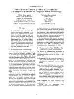
Fig 1 The Jeppeson Terminal, Denver International Airport
Fig 2 American Indian Wigwam Frame
disastrous. Therefore, to survive on this planet may make
it necessary to select order systems in which visual form
and structural form are congruent and which respect the
natural balance of the natural environment.
It is my belief that our ideas and images of what
constitutes architecture were first formed long before the
tiny fraction of the human evolution which we call
'history'. There is evidence that human dwellings of
substantial size and grouped in community settings date
back over 400 000 years. More significantly, the form
and structure of these dwellings was most likely similar
to village houses found in Africa and Asia reaching into
the last century and to the American Indian wigwams
encountered by the European settlers. Their shape
derived from the process of building the shelters using
available natural means. Flexible saplings, would be set
in the ground in a circular or oblong floor pattern.
Bending opposite members inward, lacing them together,
and adding horizontal rings, domes were formed. Two
principle patterns emerged: radial and orthogonal grids.
They are identical with the two principal engineered
dome forms we have today. Thatched with grass, leaves,
or reed, they provided protection against rain and wind,
produced ventilation and modified temperature. These
enclosures were minimal surface lightweight structures
forming comfortable interior spaces and gracious
exterior building forms. The similarity of their geometric
order (Fig.2) to recent air-supported fabric domes (Fig.3)
and the most recent grid domes is amazing.
FABRIC TENSILE STRUCTURES FOR
PERMANENT BUILDINGS
Tensile structures satisfy at least part of this challenge.
The terminal building of the new Denver International
Airport, completed in 1994, illustrates most of the
significant features of a fabric tensile structure. It took
less time to build than a conventional roof system and
provided protection during construction of the spaces
below. It weighs one tenth of any conventional roof
system. Using Teflon coated fiberglass, it cost more than
a conventional opaque
roof,
but less than any roof with
similar translucency. It reduced the cost of supports and
Fig 3 UniDome air-supported roof structure, 1975
foundations, required less mechanical equipment and
simplified the drainage. It saves energy because of the
use of daylight, the reflection of heat from the sun, and
the outward night radiation. And there is less general
maintenance. Therefore, its life cycle cost is lower than
that of any comparable roof system. Above all, the bright
interior (Fig.4 ), with its sweeping tensile shapes offers a
great space for the traveler. And the exterior sculpture is
powerful and distinctive (Fig.l). Architectural form is
identical with structural form. And the structural form I
kept as pure and direct as possible.
It is one of a number of significant public buildings
using tensile structure as the dominating architectural
feature. The roofs of the San Diego Convention Center
and of Canada Place in Vancouver have become
landmarks for these two cities. The roof structure for the
King Fadh Stadium in Riadh is still the largest stadium
cover(despite its large central opening). The Haj
Terminal of the Jeddah International Airport, now
almost 20 years old, is still by far the world's largest roof
cover. Amphitheaters, indoor sports facilities, malls,
stores,
and industrial structures are among the other
frequent areas of application.
These and many structures by other designers indicate
the successful entrance of fabric tensile technology into
the world of permanent architecture and the potential of
a larger role in the future when fabric properties will
advance and their cost will reduce, and when architects
Fig 4 Jeppeson Terminal, Denver International Airport, Interior View
220
and engineers will
be
more familiar with their design,
and when this technology
and its
forms become more
acceptable to both
design professionals
and the
general
public.
PRINCIPAL CONSIDERATIONS:
THE DENVER EXAMPLE
As
a
structural category fabric tensile structures
are a
special form
of
lightweight surface structures which
include shells, grid-domes
and
cable nets.
In
each
of
these
the
continuous spatially curved surface
is a
critical
and integral structural element.
In
tensile structures
the
surface elements, consisting
of
structural fabric
and
high
strength cables,
can
carry load
in
tension only.
The primary advantage
of
tensile members over
compression members
is
that they
can be as
thin
and as
light
as
their tensile strength permits. Consequently
the
weight
of
tensile structures
is
almost
. The
weight
of
the
Denver
roof,
for
instance,
is
10
kg/m2, which
is
one
tenth
the weight
of a
light steel truss
roof,
one
thirtieth
the
weight
of
the most intense snow accumulation which this
roof
is
designed
to
carry.
The
fabric skin
is not
only part
of
the
structure
but
also
the
building's enclosure,
requiring
no
additional dead load
for
cladding.
A further advantage
of
thin, lightweight tensile
components
is
that they
are
easy
to
ship
and
erect. Their
flexibility allows them
to be
coiled, rolled
or
folded into
small packages. Cables
can be a few
hundred meters
long, requiring
no
splices
or
internal connections. They
can
be
raised
and
connected
to
their
end
supports
by*
cranes, winches
or
helicopters, requiring
no
scaffolds.
In
fact,
the
erection time
for a
fabric structure
is
much
shorter than that
for a
conventional structure.
Form
and
prestress, rather than gravity
and
rigidity,
are
the basic means
of
providing
the
stability
and the
strength
to
carry load. Structural form becomes
a
critical
determinant
of
architectural form.
To
make
a
tensile
surface structure work, requires
a
minimum
of
four
support points,
one
more than needed
for a
rigid
structural system.
The
most basic form, therefore,
is a
four point structure. (Fig.5).
If
an
orthogonal grid
is
used,
this
is the
basic module.
One of
the
four points
has to be
Fig
5
Four Point Structure
outside
the
plane defined
by
the
other three
to
achieve
the
double curved surface which gives
the
structure
its
stability
and its
capacity
to
carry load.
The
alternative
geometry
is a
radial tent.
As
long
as
these surfaces
are in
tension
the
structure
is
stable. Under external loads part
of
the
surface
can be
permitted
to go
slack
in one
direction
as
long
as the
stability
of
the
support system
is
not lost
in
this state.
The pattern
of
surface stresses which
is
required
for the
stability
and
load carrying capacity
of the
structure
results
in
horizontal forces
at the
anchors
in
addition
to
the customary vertical forces. This
is the
price
to be
paid
for
the
advantages
of a
tensile structure.
The
skill
and
efficiency with which these horizontal forces
are
A
A
U-Cl—E2U
Fig
6
Denver Section, showing ridge
and
valley cables,
and the
building's horizontal anchor elements
anchored
or
balanced
has
a
large impact
on the
economy
of
the
structural system.
The
Denver
roof,
for
instance,
is
anchored
to the
conventional sub-structure
by
supplementing
the
existing structural frame with
diagonals
to
balance
the
horizontal forces along
the
shortest possible path.(Fig.6).
Because
of the
lack
of
structural weight, there need
to be
elements which resist upward loads from wind suction
in
addition
to the
elements which carry downward loads.
In
order
to
generate
the
structural surface grid which
satisfies
all
these requirements there have
to be
supports
at
the
high points
of
the
surface, others
at
the
low
points,
and still others located around
all
sides
of
the
periphery.
The choice
of
these support points defines
the
shape
of
the structure. Their geometry combined with
the
stress
pattern assigned
to the
surface leads
to the
form
of the
structural surface.
New
forms
can be
explored with
the
help
of
stretch fabric models which simulate
the
actual
shape rather well
and are
easy
to
make.
The
final shape
is determined with
the
help
of a
formfinding computer
program.
It
puts
all the
tensile forces
in all the
elements
in equilibrium.
For one
given configuration
of
supports
and
one
internal stress pattern there
is
only
one
equilibrium shape. Form clearly follows structural
function. Since
the
surface which
is
generated
in
this
way
is
also
the
enclosure,
the
structural form defines
the
sculptural shape
of the
building
on the
outside
and the
form
of the
space
on the
inside. There
is no
longer
any
distinction between engineering
and
architecture.
The shape
of
the Denver roof consists
of
fabric spanning
between alternating ridge
and
valley cables, with
the
periphery defined
by
edge catenaries.
Fig. 7
shows
the
entire form
of the 320 m
long
roof.
This image
is
based
on thee writer's iterative geodesic formfinding system.
Fig
7
Denver membrane grid
The photo
of
Fig.9 shows
the
completed structure.
My
initial proposal
for the
shape
was to
keep
all
interior
fabric units identical
. The
concern
was the
simplicity
and economy
of the
structure.
The
visual impact would
be naturally enriched
by the
deep perspective caused
by
the large scale,
an
effect seen
in
medieval cathedrals.
The
architects' desire
to
emphasize
the two
main entrance
points which also divide
the
terminal into three
functional sections,
led to the use of
four larger units with
higher masts.(
See
Fig.l, Fig.7,
and
Fig.9). This resulted,
of course,
in a
tremendous variation
of
shapes
due to the
continuity
of the
stress pattern.
The
impact
on
cost
was
considerable
but
probably worth
it.
Fabric
as the
surface element
in a
tensile structure
is
critical
in
maintaining
the
hierarchy
of
materials which
makes
the
system compatible. Fabric stretches more than
cables, they stretch more than rigid structural elements.
Rigid surface elements instead
of
fabric cause
compatibility problems unless frequent expansion joints
are provided
or the
surface
is
regarded
a
rigid shell
and
included
as
such
in the
analysis. There
is no
expansion
joint
in the
320m length
of the
Denver
roof.
Fig
8
Clerestory with inflated tube closure.
221
Fig
9
Aerial View
of
Denver terminal roof
Translucent fabrics further define
the
character
of the
spaces they enclose
by
bringing
in
daylight. High
reflectivity
and low
absorption
of
heat greatly moderate
the interior climate.
And the
surface geometry, together
with characteristics
of the
fabric
or of an
inner liner
control
the
acoustics
in the
space.
The
sound dissipating
geometry
of
tent shapes combined with
the
sound
absorbing surface
of the
inner liner acts
as a
"black hole"
for internal sound. Users
of
the Denver airport, which
has
an acoustic inner liner, comment
on the
quiet
atmosphere inside this busy terminal.
A feature
of
critical importance
in a
permanent building
.with
a
fabric structure roof
is the
treatment
of the
connection between
the
flexible membrane
and the
rigid
periphery wall. Clamping
the
components
of the
roof
structure directly
to the top of the
wall requires
the
wall
to
be
designed
for
substantial horizontal forces.
If the
membrane forces
are
anchored separately,
a
connection
has
to be
found which allows
for the
substantial
differential movement between fabric
and
roof
membrane.
In
the
case
of the
Denver roof with
its
high, cable
supported cantilevering glass walls
and the big
fabric
roof overhangs,
a
workable solution
was the
introduction
of
an
inflated fabric tube which allows roof movements
in
the
order
of 0.65 m at the
clerestory windows (Fig.8).
and around
1 m at the
south
and
north walls. Simple
spring operated valves
let the air
escape
and the
tube
flatten
out or
elongate.
A
small pump keeps
the
tube
inflated.
The
inner fabric liner, connected directly
to the
top
of the
periphery glass walls, hides
the
tubes from
the
inside. Fig.8 shows
the
tube before installing
the
inner
liner.
222
Fig 10 Construction of Denver roof
MAST SUPPORTED STRUCTURES
The example of the Denver terminal building shows the
principle structural features of a mast supported tensile
structure. The upper support points are formed by pairs
of masts which are spaced 46 m apart. Ridge cables are
draped over these masts and anchored to the adjacent
lower roofs similar to the main cables of a suspension
bridge. They occur every 18.3 m along the length of the
building and are designed to carry the downward loads,
Fig 11 Denver, main fabric, stressed.
mainly snow in the case of Denver. Valley cables are
placed between any two ridge cables and run parallel,
taking on the form of an arch. They carry the upward
load from wind suction and are tied to lower roof
anchors. The edges of the roof are formed by edge
catenaries outside the window walls which are anchored
against the building. Construction progressed linear
(Fig.
10),
a bay at a time, starting at the north end , and
ending at the south, where external anchors complete the
structure. The exterior fabric was stressed by pulling
down on the main connectors right outside the clerestory
walls.
(Visible in Fig.
11
at the far end of each valley
cable).
This photo shows the main fabric, stressed and
before installation of the inner liner. The cables running
parallel to the fabric seams are redundancy cables which
act as rip stops and as replacement of fabric stresses in
case of a rip or during replacement.
An interesting and integrated part of the Denver
enclosure are the cable supported glass walls around the
entire periphery of the terminal space. The south wall
itself is one of the largest glass walls built, being up to 20
m high and 67m long. The upper edge anchors the inner
liner. The deflection of the top of this wall under wind
load is only 8 cm.
Fig 12 Shoreline Amphitheater, during constrution
A few notes on a number of other mast supported
structures, pointing out features of special interest:
The roof of the Shoreline Amphitheater shows a mast
supported structure in its simplest form and largest scale.
The two masts are 45 m high, spaced 61 m apart,
supporting a roof with
8,000
m
2
of plan area. The front
edge catenary spans 140 m between two pile supported
abutments. The fabric spans between ridge cables and
edge catenaries with only a few internal cables placed
within the fabric surface for sectionalizing the membrane
and reinforcing it along a few critical lines. The fabric
was stressed by jacking the masts at the ground level.
In the roof design for Canada Place (Fig. 13) in
Vancouver the masts are placed at the ends and are
anchored back with external tie-down cables. The tent
units have a 45o skew in plan, orienting them parallel to
the city streets. This arrangement made the patterning
.1-
Fig 13 Canada Place
223
complex. But it gives the building the sail-like character
for which it has become known. The large external
moments created by the position of the high masts at the
ends was balanced by engaging two floor levels of the
building and utilizing the building's structural
components. Pairs of cables are used for the external
anchorage to provide for redundancy and to make it
possible to replace them.
In the earlier design for the Haj Terminal of the Jeddah
Airport, completed in 1982, central mast supports were
avoided by suspending the 46 m span square tent units at
their peaks. Eight suspension cables carry the load of
each unit up to the top of the 46 m high pylons, which
consist of single masts in the interior and of rigid frame
double pylon structures along the periphery of each
module as well as between modules. The roof covers a
total of 420,000 m2 or 105 acres of plan area, by far the
largest roof cover in the world.
The roof's purpose is to moderate the climate by
simulating the functions of a forest in the desert. The
translucent roof provides shade and reduces the effect of
the heat and light from the sun to about 10%. It avoids
the heat storage in the ground and its subsequent
radiating back into the space. It allows warm air to rise
up and escape through the center ring openings.
The construction of this very large project made use of its
repetitive design, which becomes visible in
Fig.
14.
The
210 tent units are arranged in 10 modules, each three
units wide and seven units long. The 21 units of one
module were assembled close to the ground. The support
ring in the center of each ring was split in a top and
bottom section. The top ring, hanging from the main
support cables, contained winches and jacks, which
could be operated from one central control space on the
site.
The winches lifted all 21 units simultaneously
within about one meter of the top ring. Four screw jacks
each were then installed. Again, simultaneously jacking
all 21 units the rings were docked, the structure fully
stressed and the rings bolted to each other. In the photo
the five modules of one side of the structure (Modules A
to E) are completed. The first module of the other side
Fig 14 Jeddah Airport
Roof:
Construction
(Module F) has been raised and is being stressed. Module
G, next to it, is being installed near the ground, soon to
be raised.
It should be noted that this process was tested on two full
scale test modules which were also instrumented with
stress sensors to check the accuracy of the computer
analysis. The test results deviated from the analysis
output by less than 5%, giving us confidence in the
reliability of our analysis process. Because of the
tremendous scale of this nearly 20 year old structure it is
becoming a test for the reliability of fabric tensile
construction.
The Riyadh Stadium extends the concept of mast
supported tent units to create the largest span roof
structure to date. (The design could have been adjusted
without difficulty to cover the area formed by the central
opening which is only one quarter of the total plan area.
Functionally this was not desired). This 247 m diameter
Fig 15 Riyadh Stadium Roof
span is achieved by arranging 24 units in a circle with an
outer diameter of 290 m, covering an area of 49,000 m2.
In each unit a main vertical mast and a smaller sloping
mast combine with triangulated peripheral tie downs to
provide the rigid supports which hold the structure out
and up. On the interior the horizontal forces are balanced
by a large ring cable with 130 m. diameter. Again, ridge
1
' : * :
Fig 16 Riyadh Stadium : start of fabric erection
224
and valley cables form the main elements to which the
fabric membrane is attached with the valleys forming the
downward anchors. The ring cable, suspension and
stabilizing cables provide redundancy and make a simple
erection feasible. Fig. 16 shows one step in the erection
process. The entire cable system is in place. Fabric is laid
out on the ground, ready to slide into position.
Note in both photos that only two fabric panel shapes
were required to make up the entire roof and give it its
dramatic shape.
Fig 17 San Diego Convention Center, exterior
The roof of the San Diego Convention Center provides a
91.5 m clear span by suspending the masts. They rest on
the main suspension cables placed 18.3 m apart, which
carry the load to triangular concrete buttresses whose
dominant forms give the building its character. The roof
structure is again formed by stretching the fabric between
ridge cables, valley cables, and edge catenaries. A
special feature of this roof design is a horizontal flying
pole with forked ends which has the purpose of resisting
the tensile forces of the two open ends.
(Fig.
18) This
makes it possible to keep the end openings totally free of
supports, giving the roof its sense of floating
weightlessness. A visually delightful feature is the so-
called rain-fly, a closure structure on top of the main roof
which covers the ventilation openings of the main
roof.
In 1997, Light Structures!Horst Berger were engaged to
provide an enclosure design for for the area under this
roof.
The schematic design proposed a convertible
enclosure to include a free standing, cable supported
glass wall at the 91.5 m long open end similar to the
south wall at the Denver airport. Movable wall panels
were to convert the space from naturally ventilated to
fully air-conditioned, curtains and fabric baffles from
bright daylight to a shading level permitting video
presentations to 6,500 people. A different scheme by a
design/construct team is presently under construction.
Fig 19 Mitchell Amphitheater, near Houston
A-FRAME SUPPORTED STRUCTURES
Tent shapes require a support at the peak of each tent
unit. Architectural spaces most often need to be free of
interior supports. Of the examples above, at Canada
Place this was resolved by moving the supports to the
edge.
The result is a space which is high at the ends and
low in the center, and a structure which is not very
efficient. At Jeddah the masts were placed at the corners
and extended upward to be able to suspend the tent units
from them, again a structurally inefficient solution. At
San Diego the masts ride on support cable which transfer
the load to the perimeter requiring heavy anchors there.
One way to resolve this problem is to replace the mast by
an A-frame. One of several such structures is the roof of
the Cynthia Woods Mitchell Center of the Performing
Arts at the Woodlands outside of Houston, Texas. It
covers 3000 fixed seats. Three A-frames form the support
system together with the stage house structure.
Horizontal anchors are avoided by introducing
compression struts which link the support columns and
edge cable anchors to the stage house, thereby balancing
the horizontal components of the membrane forces. The
supports of the A-frames form low points of the
membrane which function as drainage locations for the
rain water. The trussed columns supporting the A-frames
contain the rain leaders and support platforms for the
follow spot lighting of the theater.
Fig 18 San Diego Convention Center, interior
225
Fig 20 Mc Clain Practice Facility
ARCH-SUPPORTED STRUCTURES
For spans of rectilinear structures of up to 100 m arch
supported fabric roof systems can be highly efficient.
For domes with circular, elliptic or super-elliptic edge
shapes spans of more than 200 m can be an efficient
solution, as long as the arch components remain within
dimensions which are shippable by trucks.
A number of structures have been built using
prefabricated steel sections, often with a triangular cross
section. The largest one using such prefabricated steel
arches is the McClain Indoor Practice Facility of the
University of Wisconsin in Madison. This building
covers a football practice field. Arches of 67 m length,
spaced 18.3 m apart, span the the full width between
rigid concrete abutments. They are 2.1 m deep. Shop
fabricated in 12 m long sections they were bolted
together in the field to form half-arches. These were
lifted by cranes, pinned in the center and braced against
the adjacent arch, requiring no temporary support
elements. It took 10 days to assemble the entire arch
system. The outer quarters of the roof are covered by
standing seam, stainless steel roofing. Only the middle
half is covered by fabric membrane which spans between
the arches and is held down by valley cables. This
arrangement provides excellent natural lighting
conditions for sports by concentrating vertical light in the
center. Also the combination of the insulated opaque
roof sections with the translucent, reflective fabric roof
help reduce thermal energy consumption. Up-lighting
against the reflective underside of the roof make for good
lighting conditions in the night.
One of the many other arch supported designs was for the
tennis practice facilities of the AELTC in Wimbledon. It
uses exterior, exposed precast concrete arches from
which the fabric is suspended. This provides a neutral
geometry of the translucent ceiling which is essential for
playing tennis. It was completed in 1988.
Fig 21 Bayamon Baseball Stadium Roof Design
STADIUM DOMES
A single arch spanning 168 m was proposed to support
the cover for an existing baseball stadium in Puerto Rico.
This dramatic design illustrates one of many ways of
spanning a full size stadium facility. The arch, rising over
the middle of the field, supports two cable reinforced
fabric membranes, one anchored to a horizontal edge
beam behind the outfield, one connected to two cable
stayed masts located in front of the stadium.
Fabric structures entered the world of permanent
buildings with large and super-large spans. Geiger
Berger's low profile air-supported roof design for the US
Pavilion at the 1970 World's Fair in Osaka led to eight
stadium-size roofs built in the United States and Japan
between 1973 and 1985. All followed David Geiger's
special geometry, consisting of a superelliptic ring and a
cable net with cable lines parallel to the diagonals of the
superscribed rectangle. The economy and speed of
erection of these domes together with the attraction of
high levels of daylight of the new Teflon coated
fiberglass fabric made them win out over conventional
structural systems. They became the engine that drove
the new train of fabric structure technology.
Problems with snow melting and removal, the cost and
inconvenience of operating mechanical devices to
maintain the stability of the roof structures, and the
limitation and expense of a highly pressurized building
led owners to return to static structural systems.
This writer's first opportunity to respond to this
development with a fabric tensile roof came in 1983
with his initial design for the St. Petersburg Sundome, for
which he was the partner in charge. He called the system
cable dome. The main principle of this patented system
came from the idea of spanning suspension cables from
opposite points of the ring beam and supporting sets of
Fig 22 Original Cable Dome system developed
by author for Sundome, 1983
Fig 24 Hybrid Cable Dome system with arches as top chord
members, author, 1985
flying poles on them, similar to the basic arrangement of
the San Diego
roof.
Integrating these elements leads to
this simplest of all cable dome systems, where each cable
carries two poles, each pole is supported by two
intersecting cables. Again, one, two, or several layers can
be used, whereby each layer is added like a cantilever.
Erection needs no temporary supports.
Fig 23 Cable Dome for Sundome by David Geiger, built 1986
In the final design, carried out by David Geiger (after the
dissolution of Geiger Berger Assoc. in 1983), the
configuration was changed to a system consisting of
concentric rings and radial cables. ( Fig. 23). There
fabrication and erection is difficult. A number of other
cable dome structures have been executed, most
prominently the roof of the Georgia dome in Atlanta,
designed by Weidlinger Associates, using a triangulated
configuration.
Cable domes of this type are not efficient in heavy snow
areas because of the multiplying effect which this
geometry has in transferring loads from the center to the
periphery. This leads to very high cable quantities
accompanied by very large deflections. To avoid these
problems this writer's cable dome patent includes a
version with arch-shaped compression members at the
top.
These carry gravity loads in the most direct way to
a peripheral ring. The cable system below the arches
becomes very light as its function is reduced to carrying
part of the unbalanced roof loads, stabilizing the arches
and allowing the roof to be erected without a scaffold and
a minimum of interference with the space below.
In studying the replacement of the air-supported
UniDome roof at the University of Northern Iowa, a
cable-dome proved to be impractical. It was not possible
to adapt its radial configuration to the existing orthogonal
geometry and the first row of flying struts interfered with
the sight lines from the upper seats which is a common
shortcoming of all cable dome structures. It was also not
economical for Iowa's heavy snow loads.
The answer evolved from taking advantage of the special
nature of the existing geometry in which the horizontal
forces from the cable grid are in perfect funicular balance
with the shape of the ring beam. The initial concept was
a grid of compression elements following the same plan
configuration as the existing cable net but located above
it. The compression members were assembled from shop
fabricated, three dimensional truss sections which were
connected by vertical ties to the old cable net re-installed
below. This combination offered the most direct force
flow for downward or upward loads for the 15 000 m2
Fig 25 New UniDome, Arch and cable grid. The
cable net is that of the former air structure
Fig 26 New UniDome Hybrid
roof,
computer image superimposed
on photograph
dome spanning 140 m across the diagonal. The cable net
stabilizes the grid dome and provides sufficient bending
capacity to accommodate eccentric load cases for snow
and wind.
In the final version of the design the center section was
replaced by an arch-supported fabric tensile roof which
reduced the dead load where it is most critical and
provided translucency where it is most desired. The rest
of the roof surface is enclosed with a stainless steel
standing seam roofing on metal deck and bar joists.
Fig.26 shows the roof design in a computer generated
image superimposed on an existing aerial photograph.
The concrete ring beam which on this structure was
made of rather thin precast sections was prestressed with
tendons rapped around its exterior face to give it the
capacity to become a tension ring.
Fig 27 Prestressing tendons applied to the out
side of the existing ring beam
The construction began with the prestressing process in
the winter of 1997/98, while the stadium was in full use.
(The air-supported roof had failed in a sudden snow fall
two winters before and had been repaired with PVC
coated polyester fabric, a process which took Birdair
only weeks to complete). Parallel to prestressing, shop
fabrication of structural components took place.The
stadium remained in use until the middle of March 1998.
The new roof was completed and the first football game
took place in the stadium in October of 1998.
Fig 28 Erection of steel grid dome members.
Fig 29 Beginning of steel erection
Though a support free erection was studied, the use of
four construction masts under the intersection points of
the four continuous arches proved most practical and
economical. (See Figs. 28 and 29). The arch sections
(1.2m X 1.8m ) were shop fabricated in up to 17m
straight lengths, bolted on site into sections ready for
installation. The four long arch sections were
strengthened by tie cables. Bar joists, spanning between
arch ribs, and metal deck, spanning between joists,
followed. Insulation and stainless steel roofing was
installed parallel to the center fabric structure and the
cable net below.
Fig 30 The UniDome with its new roof
228
Under
the new
hybrid roof system,
the
natural light level
remains approximately
the
same
as in the air roof.
Over
sixty percent
of the
roof surface
is
insulated.
Air
pressure
is
no
longer required.
The
resulting energy
and
operating
savings
are
sufficient
to
finance
the
difference
in
cost
of
the
new
roof
as
compared with simply replacing
the
fabric
in the
existing
air
supported system. Above
all, the
risk
of
failure under snow load
is
eliminated.
The construction cost
was
under
$11
million.
In 14
years
time
the
life cycle cost will
be
below
the
cost
of
simply
re-installing
the
air-supported
roof.
CONCLUDING NOTES
This paper looks
at a
variety
of
fabric tensile structures
and
a
large hybrid grid dome
as
examples
of
surface
structures which each form
the
dominating architectural
feature
of a
permanent building. They
are
major projects
out
of
over
40
designs built over
the
last
25
years.
Emphasis
is on the
integrating impact, which does
not
only extend
to the
unity
of
structure
and
enclosure,
but
also
to the
building's main functions
as
control
of
light,
heat,
and
sound. Construction
is
regarded
an
integral
aspect
of the
structure.
While
a
substantial number
of
fabric tensile structures
have been built world wide, this
art and
technology
is
still
on the
fringes
of
architecture
and
building
construction.
And as the
example
of the
UniDome roof
replacement demonstrates, even
for
substantial spans
(the span
is of the
size
of
Madison Square Garden)
conventional materials
in a
grid dome configuration may*
at this time,
be
more cost- effective than
a
pure tensile
fabric structure.
Several things need
to
happen
to
make
the art and
technology
of
fabric structures
a
common component
of
the
new
built environment:
• design tools need
to
become more user friendly
so
that architects
and
engineers will
be
willing
to use
them.
•
the
cost
of
construction needs
to be
reduced. This
requires
a
cheaper, more translucent, longer lasting
fabric which
is
easier
to
handle; simpler, less labor
intensive detailing
and
construction;
and
more
use
of prefabrication.
•
a
broader acceptance
of
these
new
forms
by the
general public.
The Denver airport terminal,
one of the
very
few
tensile
enclosures
of a
regular 24-hour public building
has had
a very positive reaction.
The
Millennia Dome
can be
expected
to
have
an
important impact. Further,
by
measuring
a
building's qualities
by
standards beyond
visual excellence, fabric structures will
be
able
to
prove
themselves
as
highly desirable, when looked
at by the
slightly adjust ancient standards
of
usefulness, stability,
economy, environmental desirability
and
visual delight.
The buildings shown
in
this paper
are,
hopefully, part
of
a development
in
this direction.
It
should
be
mentioned
at
this point that
for
each
of
these buildings there
was a
design team, generally
led by an
architect, sometimes
assisted
by
other engineers. This short paper covers
too
many projects
for
comprehensive credits. They
can be
found
in the the
writers book (Horst Berger: Light
Structures
-
Structures
of
Light), which also covers
additional information
on the
subjects above. Tony
Robbin's book, Engineering
a New
Architecture, tries
to
give
an
overview
of the
potential offered
by new
engineering advances
and
ideas towards
a new
architecture.
And,
finally,
an
attempt
to set up a
broad
scope
of
objectives
for
architecture
and of the
built
environment
in
general
can be
found
in the new
issue
of
American Building.
LITERATURE
Light Structures
-
Structures
of
Light
The
Art and
Engineering
of
Tensile
Architecture
by Horst Berger, Birkhauser,
1996
Engineering
a New
Architecture
by Tony Robbin, Yale University Press
1996
American Building
The environment forces that shape
it
by James Marston Fitch
and
William Bobenhausen
Oxford University Press,
1999