KẾT CẤU MỚI THE MILLENNIUM STADIUM, CARDIFF
Bạn đang xem bản rút gọn của tài liệu. Xem và tải ngay bản đầy đủ của tài liệu tại đây (2.27 MB, 11 trang )
230
THE MILLENNIUM STADIUM, CARDIFF
Mike Otlet
Director of Engineering Design
WS Atkins - Oxford
INTRODUCTION
The Millennium Stadium is located on the site of the
original Cardiff Arms Park stadium in the heart of Cardiff
the capital City of Wales. Conceived as a prominent and
attractive landmark, it received £46 million of lottery
money from the Millennium Commission and became
one of the major projects to mark the new Millennium
(fig 1).
Fig 1
It is the first opening roof stadium in the United
Kingdom and took four and a half years from conception
to completion.
In order to hone the design and refine the details to suit
the Arms Park site, budget and programme, many
structural forms were considered.
The Rugby World Cup was to be hosted by Wales in
October 1999 and this event, provided both a catalyst and
a completion date for the project.
This paper reviews some of the key stages in the work of
the design office and fabrication workshops, which led to
the final spectacular solution. Nowadays, the design
process relies heavily on the use of computers and, in
this,
the Millennium Stadium was no exception. They
were used extensively throughout the design process for
analysis purposes and to express the design proposals.
BACKGROUND
The new stadium, which seats 72,500, was built by John
Laing Construction, over a three year period on the
restricted inner city site of the original Cardiff Arms Park
rugby ground. It has close neighbours on all sides,
including the River
Taff.
In order that the stadium can
host significant events besides rugby or football, two
sections of the roof can be moved across to completely
cover the spectator and pitch areas and form a weather-
tight arena. This closing roof is the first of its kind in the
United Kingdom and the largest in Europe. The quality
of the acoustics ensures that noise breakout is reduced to
a minimum, neighbours are disrupted as little as possible
and there is, within the stadium, an atmosphere that will
attract top performers and large audiences to the venue.
The architect HOK Lobb have balanced a series of
factors to achieve the optimum configuration that will
ensure that the spectators are close to the pitch and have
excellent sight lines, seating comfort and safety. High
quality facilities for all the family have been provided,
including restaurants, shops, bars and fast food outlets.
Behind the scenes, below the entrance concourse level
there are changing rooms with state of the art
physiotherapy and medical facilities, offices, kitchens,
storage and parking.
Unique to the project is a fully palletised system of
interlocking turf modules which can easily be lifted out
and replaced when worn or damaged (fig. 2). The whole
system can also be completely removed to create one of
the largest covered arenas in Europe, capable of hosting
almost any indoor event.
Fig 2
231
In these respects as an advanced technological building
and as a focus of urban activity and renewal, the new
Millennium Stadium can be considered to be one of the
first of the "Fourth Generation" stadia - a stadium for the
new Millennium.
STANDS
In order to hold the required seating capacity and comply
with the space restrictions around the site, the stands rake
outwards as they rise. The interesting structural solution
needed to achieve this, led in turn, to a dramatic
architectural form.
The structure above the entrance, which is at concourse
level, is constructed from 6,500 tonnes of steelwork in
CHS,
RHS, open sections and plate girders. It comprises
a series of frames at typically 7.3 m centres. The frames
are stabilised radially by concrete shear walls and,
although there are only two basic frame types with shear
walls,
either close to the pitch or remote from the pitch,
the shape of the stadium means that virtually every one
of the 76 frames is different.
The steel frames are supported by a reinforced concrete
substructure and piled foundation system (fig. 3).
Fig 3
Pre-cast concrete stepping units sit on raking steel plate
girders around the bowl to form the seating areas. At the
back of the stands, these girders carry not only the seats
but also some of the roof weight and, by means of tie rod
hangers, the extensive level 6 upper concourse. Tubular
steel props assist in limiting bending moments and
deflections in these girders.
Level 5 (Box and Restaurant level) and level 4 below
(Club level) are of pre-cast concrete slabs and are
supported by deep plate girders on steel columns. Holes
are provided in all the horizontal plate girders for
services penetrations.
A horizontally propped raking plate girder supports the
seats for the dramatic middle tier. This cantilevers 14
metres out from the floors at levels 4 and 5.
ROOF DESIGN DEVELOPMENT
The stadium needed to be about 50 metres larger than the
pitch in all directions to accommodate the 72,500 seats
and the opening had to be at least the size of the pitch.
This gave roof dimensions in the order of 220 metres
long and 180 metres wide with an opening of
approximately 120 metres x 80 metres.
At the outset, following discussions with the various
members of the team, a number of design criteria were
decided upon;
1.
To keep the roof as low as possible to reduce the
stadium's impact on adjoining buildings e.g.
Westgate Street flats.
2.
To keep the edge of the opening as low as possible to
reduce the extent of shading on the pitch bearing in
mind the requirement for roof falls for rainwater
drainage
3.
To make any structure around the edge of the opening
as small as possible, also to reduce the effects of
shadows on the pitch.
4.
To make the track for the retractable roof to move
along, as near to flat as possible, again bearing in
mind the roof falls for water run-off and drainage,
and also to assist with making the retractable roof
mechanism simple and therefore less problematic.
5.
It must be a quality design.
THE RETRACTABLE ROOF
The direction and form of the moving roof was an initial
concern. The drive systems however were not considered
to be a significant factor in this decision and have not
unduly affected the structural form since.
Due to the plan shape of the stadium seating bowl, and
the aim to create a roof as flat as possible, dome forms
were dropped in favour of linear "sliding door" style
systems running on straight rails.
Most schemes have involved two sets of 5 similar
sections combined in some manner to form a total unit at
each end of the opening.
Initial ideas centred around methods for concertinaing
sections so that they could be stored in a shorter length,
than the area to be covered, clear of the pitch.
One of the original sketches produced at the time of the
studies is shown (fig. 4). The third scheme (fig 5) was
pursued in the greatest detail and certainly could have
been made to operate successfully but the cost was
232
Fig 4
prohibitively expensive. Instead, the efforts were
concentrated on creating two 55 metre x 76 metre
"doors"
to cover the 110m long opening.
Fig 5
FIXED ROOF AND SUPPORTING
STRUCTURES
Design Evolution
There was insufficient space on the site both at the ends
and each side to allow any arch forms starting at ground
level and it was decided not to follow the tied arch and
deep truss route used on the Ajax stadium in Amsterdam,
due,
again, to the shadows created by such a high
structure. Instead the schemes investigated all made use
of masts and tension systems in an effort to improve
structural efficiency.
Scheme 1
Over the first weekend of the project we sketched some
ideas and started putting rough numbers to the member
sizes and depths, for a two mast solution, picking up 2
large lattice trusses for the retractable roof track to sit-on
(fig. 6). From this we started to get a "feel" for the scale
of the problem and the magnitude of the various elements
involved.
• -
ho„.«.,__
— . | . -V Ktl
T
Fig 6
An initial idea produced in the first two weeks of the
design process, in April 1995, was eventually to bear a
surprising resemblance to the final form.
The first scheme was developed over the following
weeks, ready for the first submission for Millennium
funding, which was made in May 1995. This,
unfortunately, was not successful.
Scheme 2
Following lengthy discussions and the consideration of
alternative sites for the stadium through the summer of
1995,
a new location, partly on the existing Arms Park
site and partly on the site of an existing BT building and
TA centre to the south, looked to be feasible. This had
the advantage of improved access from Park Street.
Again we opted for two masts to support the main
structure and retractable roof track, but this time to the
south of the stadium (fig 7). Effectively, it was the same
as the first scheme but turned through 180°. To avoid the
road, the masts were moved towards the centre line of
the Stadium and transfer structures were incorporated.
This second scheme was submitted for Millennium
funding and following close scrutiny by the Millennium
Commission and its representatives, received £46 million
of lottery money on 23 February 1996.
Fig 7
Scheme 3
Through early 1996 we had been having increasing
difficulties with the foundations and buried services that
would have been too costly to move elsewhere. When
these problems were combined with uncertainty
regarding the availability of the Empire Pool site to the
south, we started to investigate alternative mast
arrangements that did not involve such a large site. By
going back to the beginning again and considering the
options available it became clear that four masts could be
successfully employed, one in each corner at 45°, to lift
the corners of the opening. Being symmetrically loaded,
the ability to offer a more efficient design also became
possible (fig 8). After lengthy discussions with the
client, the architect et al, the four mast scheme was
eventually adopted by all in the summer of 1996 and
developed in conjunction with the contractor John Laing
Construction, through to the signing of a Guaranteed
Maximum Price, in March 1997.
Fig 8
Scheme 4
One or two adjustments in early 1997 lead to the final
arrangement we have today. These were:
i. The seating bowl that originally varied in its row
numbers to the sides of the pitch, and was deeper and
therefore higher to the long sides than at the ends of
the pitch, was rationalised to a constant level. This
deepened the radiused corners and pushed the masts
further outboard at this point requiring large diameter
columns externally to transfer the loads to ground.
ii.
A section of the original North Stand was retained,
cutting into the roof zone adjacent to the Cardiff
Rugby Club. This required structure to spread the
loads onto the existing concrete stand and an
adaptable solution to allow the roof to be extended at
some time in the future if required.
iii.The masts to the north were rotated by approximately
22° to ensure they did not encroach on adjoining
properties' land. Unfortunately the masts to the south
could not be similarly rotated and so a less efficient
asymmetric structure was the only solution.
THE FINAL SOLUTION
The Roof Covering
Both the fixed and retractable roofs are clad in a standing
seam aluminium sheet with about 120 mm of insulation
which is supported by a 128 mm deep profiled
aluminium sheet (fig 9). This was all manufactured by
Hoogevans and installed by Kelsey Roofing Industries
Ltd on-site.
This type of make-up and weight is unusual for a
stadium, but was necessary to comply with the acoustic
criteria noted earlier and allow more concerts to be held
annually.
Fig 9
The top sheet continues from the roof opening out to a
perimeter gutter, which runs practically all the way
around the perimeter of the bowl. A syphonic drainage
system, made by Fullflow, then takes the water away
from the gutters to the ground.
Roof Services
Because the roof is closed completely for special events
which require protection from inclement weather, there
are a greater number of services suspended from the roof
than would otherwise be necessary.
There are two rings of walkways running around the
stadium to access these. The first is located back from
the edge of the opening and the second in the middle of
the fixed
roof,
24 metres back from the edge of the
opening. Both walkways support heavy pitch lights and
speakers weighing up to 165kg each, together with
cabling (fig 10).
Fig 10
234
MAIN STRUCTURES
Purlins
The roof cladding
is
supported
by 14
lines
of
purlins that
run circumferencially around
the
roof
at 4.0
metres
centres.
The
surface created
is
very much like that
of an
egg with varying radii
in
both directions.
As a
consequence,
the
purlins twist from
one bay to the
next
as they pass over
the
structure below.
The
roof deck
provides lateral restraint
at top
boom level
and
small
CHS tubes provide lateral restraint
at
bottom boom level.
These tubes also provide support
to the
metal ductwork
suspended from
the roof.
Tertiary Trusses
The Tertiary trusses support
the
roof deck purlins
and
walkways
for the
fixed area
of
roof
(fig
11). There
are 44
in total generally
at 14.6m
centres around
the
stadium.
With
a
span
up to 50
metres, they
are
supported
at one
end
by the
back
of the
stands
and at the
other
by the
Primary/Secondary trusses which surround
the
opening.
To achieve good sight lines
the
trusses reduce from
4.3
metres deep
at the
junction with
the
Primary/Secondary
Trusses next
to the
opening,
to
only
400 mm
deep
at the
back
of the
stands. Here,
the
trusses
sit, via
individual
sliding bearings,
on a
perimeter truss
(fig 11). The
perimeter truss spreads
the end
weight
of the
Tertiary
Truss uniformly onto
two
adjacent stand frames.
Fig
11
The bearings ensure that differential horizontal
movements between
the
roof
and the
stands will
not
have
an adverse effect
on
either element,
e.g.
under wind loads
and thermal expansion/contraction.
Primary Trusses
Two major pieces
of
structure, known
as the
Primary
trusses,
are
located
on
each side
of the
pitch
in a
north/south orientation.
Rising
35
metres above
the
pitch, these
are
continuous
over
the
full
220
metre length
of the
stadium
(fig 12).
Support
is
provided
at two
intermediate positions
(at the
corners
of the
opening)
via
cables
up to the
corner masts
which
are
then tied down
to
anchors outside
the
stadium.
With
a
1067m diameter
top and
bottom boom,
the
trusses
range
in
depth from
4
metres
at
each
end to 13
metres
in
the centre.
Fig
12
A
778 dia.
middle boom, four metres above
the
bottom
boom, provides
a
connection point
for the
tertiary truss
top booms
and
resists high compression loads from
the
mast structures,
(ref.
analysis)
On
one
side
the
trusses provide
the
support
and
rigidity
for
the
continuous runway beam which support
the
moving
roof. On the
other side they provide support
for
the fixed roofs
on the
east
and
west
of the
opening.
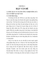
235
Secondary Trusses
The secondary trusses run in an East-West orientation
and trim the North and South edges of the opening. They
traverse the full 180 metres width of the stadium and are
formed from a 915 diameter top boom and 550 diameter
bottom boom (fig 13). Support is provided at each end
by the stand structures, and at the intersection points with
the Primary Trusses, by the corner mast and cable
assemblies. They principally provide support to the pitch
end of the North and South Tertiary Trusses and also by
a lesser extent, to an area of roofing to the corners.
Fig 13
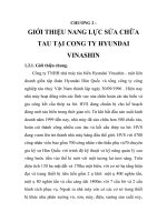
Bracing and Lateral Restraints
The fixed roof is connected together to perform
structurally as one homogeneous unit. The straight,
rectangular, roof areas are braced in both directions on
plan at top and bottom boom level for stability and lateral
restraint purposes (fig 14).
FIXED
POSITKJNS
<RJ.
Fig 14
The purlins perform the role of lateral restraint, at top
boom level, with CHS tubes at bottom boom level.
In addition the bracing holds the track for the moving
roof in position laterally. This requires both levels of
bracing to resist the torsion effects of the moving roof
loads being applied eccentrically to the Primary Truss.
The corner tertiaries are restrained back to the adjacent
parallel roof section (either east-west or north-south).
The total roof is trimmed by a 4060 CHS which supports
an eccentrically applied cladding load and holds the
shallow Tertiary trusses vertical at the bearing positions
on the perimeter trusses.
THE CORNER MASTS
Four corner mast structures are key to both the vertical
support and horizontal stability of the roofs. Each mast
structure is made up of a pair of lower columns (concrete
filled steel tubes 12190) which sit upon a 16000
fabricated steel tensioning chamber which, in turn, rest
on reinforced concrete foundations (fig 15). The
tensioning chamber is connected to an 8m deep
reinforced concrete shear wall via 10 no. 750 Mac Alloy
bars cast into the wall. On top of the pair of lower
columns is a complex series of connections commonly
known as the elbow and knuckle. The elbows form the
link between the roof and the stand structures providing
total stability horizontally to the roof via the eight
elbows, in 4 pairs, and the cross-bracing between them.
Fig 15
The A-frame mast rests on the knuckle and is held down
by the high tensile forces in the cables which on one side
lift the main roof and, on the other, are tied down to the
tensioning chamber at the base of the pair of concrete
filled steel columns.
The high tensile forces in the cables generate
compression in the two horizontal structures. On the
pitch side these are known as the Mast Tertiaries. These
are fabricated units 2.6m deep and are made of 60mm
thick plate to form a Tee-shape section which were then
welded to a 6600 CHS tube at the bottom. Pairs of Mast
236
Tertiaries are braced together for stiffness and buckling
resistance. On the other side of the knuckle outside of
the stadium, is an A-frame outrigger made from 9150
CHS tube. The tubes are restrained by a tensegrity
structure to stop the outrigger from bowing under its own
weight. This also provides buckling resistance.
The A-frame masts rise 40 metres above the edge of the
roof and 70 metres above the surrounding ground level
(74 metres above the pitch). Each leg is a fabricated oval
section 915 x 1415 overall, tapering down to 9150 at the
knuckle. Again, as with the outriggers, the mast A-frame
is restrained by a tensegrity system of McCalls tie rods
and struts.
The tension system, although loosely described as cables,
is in fact a group of 15 mm diameter high tensile steel
strands by PSC Freyssinet inside 6 No. 2730 HDPE
sleeves.
FTOM
iro or mmm
rrrrcs
(70™.
tuxi
Fig 17
MOVING ROOF
There are two moving roof sections that are generally
located one to the north and one to the south of the
opening over the fixed roofs. Both sections are 76 metres
wide and 55 metres long and made up of 5 individual
units,
each 11 metres wide (fig 16). The units are linked
together, principally at the ends with vertically orientated
sliding bearings. Each unit is prismatic in cross section
and 8 metres deep at the centre. The truss curved in
elevation has a single CHS top boom and two CHS
bottom booms. The flat roof deck sits on purlins above
the bottom boom with all diagonals and the top boom*
exposed to the elements. The units are allowed to move
differentially horizontally (fig 17) to accommodate
curvature of the track on plan. Sliding bearings are
provided above the wheels to cater for variations in the
distance between the two retractable roof runway rails.
The retractable roof units were assembled at ground level
and lifted onto the roof in 76 metre sections. Since
positioned and connected, it has functioned well with
few problems.
ttCTXX
THROUOM
WfSt
SK*
THE MECHANISM
The moving roof sections have no power connection to
them whatsoever. The actuating mechanisms are
mounted on the fixed roof between the track and the
Primary Truss (fig 18).
Fig 18
Fig 16
237
These are on each side of the moving roof located at the
four comers of the opening to pull each half of the roof
open or closed via a cable loop (fig 19). This operation
takes 20 minutes in each direction, a speed of only 2.6
metres a minute.
Fig 19
A system of hydraulic motors and gearboxes power the
drums back and forth. Substantial brakes are provided to
each drum. Hydraulic buffers are located at the centre of
the travel and where the units rest at the outer ends of the
track, as end stops (fig 20). The speed and actuation are
all computer controlled such that both sections move at
the same time and at the same rate.
Fig 20
ANALYSIS
The roof was initially broken down into simplified 2D
frames before the assembly of a complete 4349 member
3D roof model (fig 21). The model was developed over
three months in order to reduce the highly loaded and
high displacement/deflection points to acceptable levels.
Fig 21
Wind Tunnel testing was carried out prior to the
commencement of the design to ascertain the most suitable
wind loads to be applied to the roof analysis model. This
also provided an opportunity to check the effects of the new
stadium on the surrounding buildings.
The 3D model was loaded with self-weight, dead load, live
load and wind load cases individually and then with
combined load cases with the retractable roof units in open,
closed and partly closed positions. The output was then
sifted to obtain the worst combination of axial and biaxial
bending stresses for each roof member.
The model was refined to improve structural efficiency and
uniformity in truss boom sizes. The Primary Trusses were
pre-tensioned by varying amounts until the optimum
location and pretension were determined. This showed that
maintaining the theoretical Primary/Secondary truss
intersection node "level" following installation of all the
dead load and retractable roof trusses was the best solution.
This meant that the cable system had to be shortened by
approximately 500 mm at ground level to achieve the
required position.
During the construction period, sections of the model were
deleted to reflect the partially constructed state. Further
analysis was undertaken to ensure that the partial stability
and strength of the roof structure and its various components
during the erection period were satisfactory. These figures
were then used during the tensioning sequence for
comparison purposes with the actual figures measured on
site.
CONSTRUCTION AND CONNECTIONS
All the steelwork for the stadium was manufactured in the
UK by British Steel (now Corus) and shipped to Italy for
fabrication by Costrusioni Cimolai Armando SpA.
Due to the large size of all the trusses it was necessary to
subdivide them into transportable sections no bigger that 5
metres by 17 metres. It is interesting to note that seventy five
percent of the roof structure is there purely to support its own
selfweight.
238
With this in mind it is obviously important to keep the
selfweight to a minimum. Given that the steel was being
transported from Italy to Wales after fabrication it was
important that the connections between each piece were
both small and efficient. During the fabrication drawing
period the Primary truss which was previously a 3-
Dimensional prismatic form was redesigned as a 2-
Dimensional element for ease of transportation and in
particular shipping. Additional lateral restraints were
required as a consequence.
From an early stage it was decided to follow the simple
principle for the connections of:
i. The ends of complete trusses or members would be
emphasised architecturally within the practical
constraints of tolerance, fit-up and economy.
ii.
All intermediate (splice) connections would be
hidden to give the impression of being a continuous
monolithic piece.
In the majority of cases such as the tertiary truss ends and
lateral restraint/bracing member end connections, a
simple tapered tube detail was developed with single
plates protruding. A plate each side with multiple bolts
in a circular arrangement then linked the pieces together.
Tolerances for length and direction were achieved via
four interfaces each with 3mm oversize holes for M27
bolts (fig 22).
Fig 22
The connections for the mast assembles were considered
individually due to their varying requirements of
movement, tolerance and adjustments
The Primary node which connects the Primary,
Secondary and Mast tertiaries together as well as
numerous smaller bracing and lateral tubes is formed
from a single 100mm thick high grade steel plate cut to
the external profile of the overall connection, (fig 23)
The plate is orientated vertically in the direction of the
cables to enable the tube and cable termination housings
to be welded directly to each side. Short stubs for the
incoming truss members were then welded at the
appropriate angle onto the central plate to give sufficient
space for bolted splice connections to be made. Where
forces were prohibitively high in-line butt welds were
made on site, but these were rare.
Fig 23
The mast top cable termination, outrigger end cable
termination and base tensioning chamber all followed the
same principle of the single central plate cut to the
external profile of the connection. All other plates and
tubes were then welded to the sides of this (fig 24). Cover
plates (bent plates) welded outside these have ensured
that the external appearance is as smooth flowing as
possible, within' the budget constraints. The use of a
central plate has ensured that the forces flow more evenly
across the connection and high local bending moments
and shear forces were kept to an absolute minimum.
Fig 24
239
The knuckles which are located at eaves level on 1219 A
tubular columns form the focus and connection point for
the A - frame masts, Outriggers and Mast tertiaries (fig
25).
This central knuckle (or hub) has to resist
approximately 40000 kN axial compression from each
incoming member. During the cable tensioning process
and when the retractable roof sections close, or when it
snows, the forces in the cables (which join the outer ends
of those members) increase, causing them to elongate
significantly. This in turn causes a rotation at the knuckle
necessitating a pivot at the same point.
Fig 25
A 2.4m diameter cylinder 2.4 metres long orientated
horizontally, like the centre of a bicycle wheel has around
it removable steel plates with PTFE and stainless steel
contact surfaces to allow the small rotation to occur (fig
26).
The drum was sized to accommodate the very large
circular end plates from each of the three incoming
members with the low working stresses in the PTFE
material
Figure 26
The splice connections between the Primary and
Secondary trusses required the greatest development
time.
Various options were considered (some of
considerable weight and complexity) before the final
detail was found. Bolted connections were considered to
be essential for speed and ease of construction. Due to
the large diameter of the tubes involved (770 diameter
and above) it was possible to climb inside to make a
hidden bolted connection(fig 27).
Fig 27
The majority of tubes are highly stressed and an
innovative detail was required to solve the problem.
The axial loads are transferred by 4 flat plates bolted to
fabricated tees welded to the inside of the tubes (fig 29).
The tees are of sufficient depth to allow the splice plates
to pass over an internal flange on the ends of each
section. The flanges are bolted together to transfer shear
and torsion.
Where tubes were too small to climb inside, port holes
were formed to gain access to the bolts and flange
plates.
Figure 28
240
The 355 diameter bottom booms of the tertiary trusses
were too small for this detail and instead a steel
cruciform was welded into each transportable section (fig
29).
Flat splice plates were used to link the pieces
together. Cover plates flush with the outside of the tube
hide the splice.
Fig 29
SUMMARY
The 8000 tonnes of roof steelwork was erected and clad
in only 10 months. This was made possible by the design
of practical, workable site connections and the assembly
of large sections (generally 50 metres long) at ground
level lifted into the air with an 1800 tonnes crane. This
avoided the use of scaffolding and minimised work at
high level. To design the first retractable roof stadium in
the UK has been a long and at times difficult process due
to the varying interests of the people involved.
Structurally it has been a wonderful challenge and
opportunity to design to a scale rarely experienced by
most engineers, (fig 30)
The deadlines were achieved and I believe the results
speak for themselves. The next one will be easy!
Figure 30
Client
Welsh Rugby Union in conjunction with South Glamorgan County
Council (later formed into Millennium Stadium Ltd)
Funding
£46 million Millennium Funding
Architect
Lobb Sport (now HOK Lobb)
Civil and Structural Engineers
WS Atkins
Main Contractor
John Laing Construction
Mechanical & Electrical Engineers
Hoare Lea & Partners
(Detail design by Ove Arup and Partners for Drake and Scull)
Steelwork Fabrication
Costrusioni Cimolai Armando SpA
Roof Covering
Kelsey Roofing Ind Ltd