KẾT CẤU MỚI THE DESIGN OF THE ROOFS OF THE BRITISH MUSEUM AND THE MUSIC CENTRE AT GATESHEAD
Bạn đang xem bản rút gọn của tài liệu. Xem và tải ngay bản đầy đủ của tài liệu tại đây (2.72 MB, 11 trang )
276
THE DESIGN OF THE ROOFS OF THE BRITISH MUSEUM
GREAT COURT AND THE MUSIC CENTRE AT GATESHEAD
Spencer de Grey
Architect
Foster and Partners, Architects and Designers
ABSTRACT
This paper provides the background to the design of two
current projects by Foster and Partners. The British Museum
Great Court in London and the Music Centre at Gateshead
have a single major architectural feature in common - both
are covered by lightweight, large-span roof structures. The
complex geometries of the roofs have required cutting-edge
computer models and parametric modelling software to
assist in the design process. Technically, the two roof
structures are amongst the most advanced of their kind.
But the two projects share themes that have more far-
reaching cultural and philosophical ramifications than the
technical virtuosity of their structures. Both create new
democratic urban spaces - public spaces that serve not only
as circulation areas for their respective buildings but also as
internal piazzas for their respective cities at large. Each
project involves 'repairing' its site - the British Museum
Great Court reclaims a space that has been lost to the public
for more than 150 years and the Gateshead Music Centre
makes a major contribution to the cultural redevelopment of
the derelict south bank of the River Tyne. The Great Court
will be completed in November 2000, and the Music Centre
at Gateshead, which is still in design development, will be
completed in late 2002.
Figl
I will begin by outlining the historical background to
each of the projects, focusing on the ways that each of
the buildings deals with broader issues of urban
planning. This will be followed by a description of their
sites and the functional requirements that led to the
development of wide-span structures. I will conclude
with a brief technical description of the structures and
their energy strategies.
Fig 2
277
HISTORICAL BACKGROUND TO THE
PROJECTS
The Music Centre at Gateshead is a central part of the
regeneration of the Tyne riverside. Other key projects
include the new Baltic Centre for Contemporary Art and
a new pedestrian bridge by Chris Wilkinson. The area
will be further enlivened by shops, a hotel and leisure
facilities.
The Music Centre complex will provide accommodation
for three auditoria and the Regional Music School. Each
of the auditoria has been designed to provide acoustic
excellence in relation to the number of seats required. As
such, the exact forms of the three spaces have essentially
generated themselves along functional lines. The largest
hall will seat 1650 people. The second hall is intended for
folk, jazz and blues concerts, including those by the
resident Folkworks, and will have an informal and
flexible seating arrangement with a maximum capacity
of 400 seats. The third hall will be used as a rehearsal
space for the Northern Sinfonia and a major performance
space for the music school. The three auditoria are
conceived as separate enclosures placed alongside each
other on the riverbank.
Fig 4
It would have been possible to leave the auditoria as
three discrete buildings, housing their own foyers and
auxiliary spaces. However, the specific characteristics of
the site and the future development of the quayside
suggested an alternative solution - a large roof structure
enveloping the auditoria. Firstly, the windswept nature of
the site required some kind of common shelter for the
three buildings. Secondly, the building complex needed
to supply its own access routes and infrastructure on
what was a totally derelict site. Both issues suggested the
need for a concourse, in the form of a covered 'street' on
the riverfront, beneath a large roof structure. Below the
concourse is the music school. This concourse becomes
a major public space - a shared foyer for the three
auditoria, a common room for the music school, and a
sheltered environment from which to enjoy the river. It
symbolises the ethos of cultural fusion inherent in the
establishment of the Music Centre - a complex shared by
musicians and audiences of a range of different music,
and a meeting point for students, professional performers
and the public. This integration has been encouraged by
reducing the back-of-house hospitality areas for
performers, so that visiting musicians will meet with
students and their audience in the concourse bars. Lastly,
the roof gives visual cohesion to the project, and
provides the waterfront with a landmark structure that
formally echoes the great arch of the neighbouring Tyne
Bridge.
Fig 5
The Great Court project at the British Museum is, at one
level, a solution to the problems of welcoming visitors to
one of the world's busiest museums and providing a clear
primary circulation route from which they can visit the
many galleries. But it also rescues from obscurity one of
the most impressive public spaces in the capital - a
courtyard the size of the football pitch at Wembley
Stadium.
278
The present British Museum building was designed by
Sir Robert Smirke to house the King's Library and act as
a permanent home for the collections of the museum
founded in 1753. Completed in 1847, Smirke's design
was conceived as four wings of galleries arranged around
a central quadrangle. Measuring 96 x 72m, this courtyard
was to be used as a breathing space at the heart of the
museum - a space to perambulate, relax, talk and think
about the museum's extraordinary collections.
Unfortunately this dramatic space existed for no more
than five years. Almost as soon as the building was
completed, it became clear that there was insufficient
space for the museum's growing collections. The
solution, conceived by the then Keeper of Printed Books,
Antonio Panizzi, was to construct the great circular
Reading Room within the central courtyard. Sydney
Smirke, who had succeeded his brother as the museum's
architect, began construction of the Reading Room in
1852.
Completed in 1857, it is undoubtedly one of the
most impressive and beautiful interiors in London.
Fig 7
The remaining space between the facades of the museum
quadrangle and the drum of the Reading Room was
gradually filled in with buildings to house the ever-
growing collection of books that now constitutes the
British Library. These book stacks were extended
between the wars, partly damaged in the Second World
War and subsequently re-built. As a result, not only was
the central courtyard lost to the public for over 150 years,
but the museum was robbed of a primary circulation
route. This problem became more acute as the museum's
popularity grew. Today it has a worldwide reputation for
the scope, quality and rarity of its collections and for its
role as a centre of education and scholarship. Every year
the museum attracts 5.4 million visitors compared to the
Louvre's 5.7 million and the New York Metropolitan
Museum's 5.2 million.
The museum's entrance hall is a magnificent space but its
plan dimensions are small and contained. It now has to
accommodate seventy times more people than allowed
for by the original design, so that it is constantly packed
with visitors and is a frustrating and disorienting space
from which to move on to the galleries.
The removal of the British Library to a dedicated
building at St Pancras has left the accommodation in the
courtyard empty, freeing approximately 40 per cent of
the museum's area. This has provided the perfect
opportunity to establish the Great Court as the museum's
central orientation space. The undistinguished post-war
buildings that served as bookstacks have been
demolished to recreate the courtyard at the heart of the
Museum. The Reading Room is retained, serving as a
reference library and a multi-media information centre
about the museum's collections. Upon completion of the
project, the Reading Room will be open to the general
public for the first time in its history.
Fig 8
In order that the Great Court can be used by visitors all
year round, it is being covered with a lightweight roof
that spans the space between the facades of Sir Robert
Smirke's original quadrangle and the drum of Sydney
Smirke's Reading Room. The lightweight roof is
designed to let in light and keep out rainwater. This
creates an indoor piazza - the largest of its kind in
Europe - that will be open outside normal museum
hours,
providing London with a dramatic space for
evening events. The courtyard links the main museum
279
entrance on Great Russell Street, via the new gallery in
the North Library, to the rear entrance on Montague
Place, establishing a public thoroughfare directly through
the centre of the museum.
In this respect, the project can be seen in a much wider
context. It offers the opportunity of establishing a new
diagonal route - a cultural route - across London,
perpendicular to the River Thames. This route starts in
the north with the new British Library and the three
major railway stations - Euston, St Pancras and King's
Cross.
It continues through Russell Square, leading to the
extensive area occupied by London University. Opposite
Senate House, the British Museum and Great Court with
its through-route and covered public space is a focal
point. The route then moves south to Covent Garden,
which attracts in excess of 10 million visitors each year.
The improved pedestrian walkways on Hungerford
Bridge, currently under construction, link Covent Garden
with the revitalised South Bank and the international
terminal at Waterloo Station.
Fig 9
Fig 11
280
THE DESIGN OF THE ROOFS
The Gateshead Roof
The starting point for the Gateshead roof was to design a
structure that would shelter the auditoria, the concourse
and the music school beneath the concourse in the most
efficient manner, closely hugging the buildings, and
generating a form that would unify the complex. Initially
a tensile structure was considered, but was abandoned in
favour of a more permanent solution. Three adjacent
shell-forms were generated. Initial these were entirely
free-form shapes - not governed by any geometry.
However, it was clear that it would be necessary to make
the roof conform to geometric rules in order to rationalise
the setting out and the manufacture and construction of
the building components. Parametric modelling was
employed to do this.
GcwMion
of
COM
Section
erntntion
of
Spiral
AA*H
Enclosure Geometry
Fig 12
In long section, east to west, the roof is a series of arcs
that meet tangentially. These arcs are rotated
longitudinally to create a toroidal geometry. The
parametric model allowed the architects to alter the radii
of any of the arcs and immediately generate a new roof
form. This meant that recalculating the information each
time a change was made, which would have taken hours
or days if done conventionally, could be done within
seconds. In response to structural, financial and aesthetic
issues, the design team generated more than 100
alternative roof designs, sometimes mocking up 4 or 5
schemes per day. Such a degree of responsiveness would
have been impossible without the parametric model.
The roof has an area of 10,200 m2, spanning a distance
of 100 metres north to south and 115 metres east to west.
The three shell forms are cut at the rear and cantilever at
the east and west edges to provide entry canopies. As it
swoops down to the riverfront a portion of the roof is
glazed. At the mid-point, the roof varies in height from
22 to 37 metres. The majority of the roof is clad in 2mm
rain-screen stainless steel. This sits 600mm above a
waterproof membrane. The glazed area on the riverside is
1,700 m2, with a 20m2 free area of high-level opening
glass.
The roofing system ensures that all panels, whether
solid, glazed or louvered are interchangeable. The
faceted roofing panels vary in length, but have been
rationalised to only twelve different widths.
Fig 14
The steel structure consists of four primary arches running
north to south, which are 838mm universal beams. These
are supported by sixteen props, which are 457mm circular
hollow sections. There are an additional four props, which
are 323 circular hollow sections, for each of the two
cantilevered entrance canopies at the eastern and western
edges.
The props are set out radially. The secondary arches
run east to west and are 406mm universal beams. The
tertiary members running north to south are 168mm
circular hollow sections. This integrated structural system
is further braced with diagonal rods of 32mm diameter. The
three main sets of structural elements are fixed with bolted
connections, while the diagonal bracing is pinned. The
whole forms a continuous shell structure.
Fig 13
281
The Great Court Roof
The key element of the design for the Great Court is the
glazed
roof.
The underlying strategy is to produce a
canopy that is delicate and unobtrusive, avoiding the
need for columns within the court, which would obscure
the handsome internal facades of Smirke's building.
Geometrically the roof has to negotiate the space
between the Reading Room and the surrounding facades
and is constrained by planning requirements, which limit
its height relative to existing structures. The roof had to
be constructed of components that would be small
enough to be lifted into position by crane, there being no
other access to the construction site. This has resulted in
a geometrical form, generated by a complex
mathematical model, in which, despite its apparent
simplicity, every single triangular glazing panel is
unique.
Fig 15
The roof is 6100m2 and comprises 3312 triangular glass
panels. Only the north-south axis represents a line of
symmetry for the roof because the Reading Room is off-
centre within the Great Court by 5m towards the north
facade. The structure spans lengths varying between 14
and 40 metres. The varying lengths result in the mid-
point heights of the roof varying from 3 to 7 metres in
relationship to the horizontal boundaries. The maximum
distance from the floor level of the Great Court to the
highest point of the roof is approximately 26m. The
triangular glass panels vary in size from 800mm x
1500mm to 2200mm x 3300mm; the average area of the
glass panels is approximately
1.85m2.
Fig 16
The double-glazed units are assembled with an outer
'monolithic' lOmm-thick, toughened-glass panel; a
16mm air-filled cavity and an inner laminate glass,
comprising two panes of clear-float glass and two clear
PVB interlayers. The total thickness of the glazing unit
is 38.76mm.
The roof allows daylight to filter through and illuminate
the court, passing into the Reading Room and, in very
controlled quantities, into the surrounding galleries. In
order to reduce solar heat gain the glazing units combine
body-tinted glass with a white dot-matrix fritting
pattern- over 75% of the sun's heat is prevented from
entering the court - while a high proportion of the visible
spectrum is transmitted.
The glazing panels are supported on a fine lattice made
up of 5162 purpose-made steel box beams that intersect
at 1826 structural six-way nodes, each totally unique in
its x, y and z co-ordinates and rotation angles. The
80mm-wide roof members are both the primary structure
and the supporting frame for the triangular glazing units.
The structure consists of 10 km of steel.
Fig 17
An extruded silicone gasket provides the interface
between the supporting steel frame and the glass panels.
This 15mm-high gasket is not only shaped to cater for the
angles at which each of the panels meet - varying
between nearly 0° and 30° - but also to respond to the
combined system's tolerances. As the steel roof
members and nodes are fabricated through computer-
controlled machining, precise tolerances can be achieved
in the steelwork fabrication.
282
The glazing panels
are
mechanically restrained
by
means
of stainless steel bolts
and
cleats, fixed
to the
steelwork
at approximately 500mm centres around
the
double
glazing units' perimeters.
The
double glazing units
are
manufactured with stepped edges, which provide
the
beaming surface
for the
fixing cleat.
At
its
junction with
the
Reading Room
the
roof
is
supported
on a
ring
of 20
composite steel
and
concrete
columns which align with
the
structural form
of the
original cast-iron frame
of the
Reading Room. These
columns will
be
concealed
by a new
skin
of
limestone
surrounding
the
entire drum
of the
Reading Room,
the
exterior
of
which
was not
designed
to be
seen from
within
the
museum. This skin also provides space
for
vertical services.
At its
perimeter
the
roof
is
supported
by
Smirke's original load-bearing masonry walls.
It is
connected
to the
walls
by a
sliding bearing carried
by a
concrete ring beam surmounting
the
existing walls.
The roof's glazing system
has
been designed
to be
walked
on for
cleaning
and
maintenance.
To
ensure
operatives' safety
200
harness attachment points, linked
by continuous cables, have been provided
in
strategic
locations across
the roof.
Both glass
and
steel have been
designed, fabricated
and
installed with fully tried
and
tested technology
and
rigorously tested before assembly.
Fig
18
Heating
and
Ventilation Stategies
With both projects
we
have attempted
to
rely
as
much
as
possible
on
passive systems
of
cooling.
The
aerodynamic form
of the
Gateshead roof assists
in a
system
of
natural ventilation.
The
south-west wind
is
drawn over
the roof,
creating
an
area
of low
pressure
at
the building's riverside facade. This encourages
air to be
drawn
in
through low-level opening vents.
A
natural
stack effect
is
created
and air is
exhausted through high-
level opening glazed panels. This system
is
augmented
with mechanical ventilation that supplies
air and
warmed
air as
necessary. Heating
to the
concourse
is
provided
by an
under-floor system using hot-water
pipes.
The
auditoria
are
fully air-conditioned.
At
the
British museum
it was
important
to
integrate
modern services with minimal alteration
to the
building's
historical structure. Having sealed
the
Great Court
in
order
to
keep
the
weather
out, it is
necessary
to
bring
fresh
air
into
the new
spaces
and the
Reading Room
at a
rate
of
45m3/
second. This
is
achieved
by the
construction
of
four
new
primary plant rooms
in the
basement
of the
existing buildings
to the
north-east,
south-east, south-west
and
north-west
of the
court. These
perform
the
initial filtering
of the
incoming
air
before
it
is passed
to
four secondary plant rooms beneath
the
court. Within these, full conditioning
of the air
takes
place before
it is
distributed
to the
education centre,
gallery spaces
and the
restored Reading Room.
In
the
Reading Room
the new
systems follow,
in
broad
principle,
the
original strategy
of
Smirke's design
by
using
the
existing 'spider'
- a
series
of
brick
air
ducts
to
carry insulated ductwork beneath
the
floor
to
supply
air
through
the
reading desks.
The
extract system will also
use
the
original routes
in the
structure
of the
dome.
The first level
of
environmental control
is
provided
by
passive, natural ventilation.
Air is
drawn
in
through high-
level openable louvres around
the
perimeter
of the
Great
Court. These, combined with
a
direct fresh-air feed
to the
floor-recessed displacement louvres, produce
a
large
stack effect
and
wind effect
to
self-ventilate
any
internal
heat gains.
The
passive system
can
also
be
used
to
'purge'
the
entire volume
at
night when outside
air is
much cooler. This prevents
the
'heat soak' from which
many large structures
can
suffer
if
they
are not
allowed
to
'breathe'
at
night.
During
the
winter months,
the
Great Court
is
heated
by
an underfloor heating system with
a
network
of
pipes
in
the screed.
To
enhance cooling
in the
galleries
and
auditoria during
the
summer,
the
same pipes
are
used
for
a chilled water system.
At
night, when
the
galleries
are
closed,
the
central chiller plant
is
redundant.
It is
therefore possible
to run
this plant outside
of
occupied
periods, using off-peak electricity
to
feed cold water
to
the slab. This then pre-cools
the
large floor area
to
approximately
18°C in
preparation
for the
following
day.
The chilled slab encourages fresh
air to
remain
at
floor
level rather than being drawn into
the
higher, unoccupied
volume
of the
space.
The
resultant scheme allows
the
Great Court
to be
maintained between
a
minimum
temperature
of 18°C in
winter
and a
maximum
temperature
of
25°C
in the
summer.
283
Engineering
the
British Museum Great Court Roof
Stephen Brown
Parner, Buro Happold
The British Museum
is one of
England's most popular
venues, visited
by
millions
of
tourists, students
and
academic researchers every year.
To
create more space
for
the
Museum's continuing expansion
and
modernisation
of its
visitor facilities,
it is
witnessing
change
on a
scale never before experienced
on
this
tightly populated site
in
Bloomsbury.
THE DESIGN
The architectural scheme proposes spanning
the
Great
Court,
and
encircling
the
grade
one
listed Reading Room,
with
a
graceful streamlined glass roof enclosing
the
court
below, providing
a
sunlit, comfortable space
for
visitors
and museum
staff. To
meet
the
requirements
of
planning
consent,
the
height
of the new
roof construction
is
restricted
and the
support
of the
outer perimeter
on the
quadrangle buildings does
not
visually intrude
on, or
structurally disturbing
the
classical Georgian facades that
face into
the
Great Court.
The roof
is a
fine lattice shell structure spanning
in
three
directions from
the
four sides
of the
quadrangle
on to a
ring
of 20
columns that will surround
the
Reading Room.
The Reading Room
is
actually
not
located
at the
centre
of
the courtyard,
but
some
5m
towards
the
North facade.
These columns carry
the
roof load down
to the
foundations
ensuring that
no
additional load
is
applied
to the
Reading
Room. They will
be of
structural steel composite
construction
to
achieve
the
required fire rating
and
stiffness
to
span from floor level
to the
snow gallery while
remaining slender enough
to be
hidden behind
a new
stone
cladding
of the
Reading Room.
The
columns designed
in
accordance with Eurocode
4
will
be
fabricated using
tubular steel,
an
outer 457mm diameter reinforced with
an
inner 250mm square
and
filled with concrete.
Around
the
Reading Room,
of the
roof will
be
prevented
from spreading laterally
by the
Snow Gallery, which acts
as stiff diaphragm balancing
the
thrusts from opposite
sides
of
the
roof. To
achieve this
the
existing brick arched
snow gallery will
be
demolished
and
replaced with
a new
reinforced concrete construction which will also house
the main extract fans.
On the
other hand, around
the
outer
perimeter
of the roof, to
avoid applying
any
lateral load
to
the
quadrangle buildings,
the
roof
is
supported
on
sliding bearings. These bearings allow
the
roof
to
spread
laterally under load
,
normal
to the
relevant facade,
independent
of the
buildings. This freedom means that
for
the
roof
to
hold
its
form,
the
outer radial members
near
the
perimeter quadrangle must work
in
bending
and
284
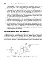
Roof Plan colours show how the stress corres[ponding element size
varies.
The torodail framing of the roof has been generated to
provide an easy transition from the circular form of the
Reading Room to the quadrangle of the surrounding
Museum buildings. The geometry has been defined using
customised form generating computer programme
resolving both the architectural and structural
requirements. Forming a smooth flowing roof that
adheres to the height restrictions while curving over the
stone porticoes in the centre of each of the quadrangle
facades. The high points in the roof are located such that
the lateral forces exerted on the Snow Gallery from
opposing sides of the roof are generally balanced,
minimising the risk of any nett force being applied to the
Reading Rooms iron frame. As a further precaution the
new reinforced concrete snow gallery will be supported
on sliding bearings, so that the stiff ring floats above the
historic frame.
THE STRUCTURAL GRID
The roofs structural grid follows that of the glazing
supporting each panel along its edges minimising the
complexity of the glass fixing. Therefore, the maximum
size of glass available set the final structural grid size.
The grid is formed by radial elements spanning between
the Reading Room and the quadrangle buildings, that are
inter-connected by two opposing spirals so that the roof
works as a shell. While rectangular fabricated hollow
sections are the preferred structural solution for the
structural elements, a alternative slightly finer option
using solid sections has been prepared. For both options
the elements taper to smoothly accommodate their
increasing depth towards the Quadrangle buildings. This
reflects the architecture maintaining the sharp flowing
lines of the structural elements dividing the individual
glass panels. With the roof having only one line of
symmetry, there are individual 1826 structural nodes
where six elements are connected. All connections must
fixed to transfer the forces and bending moments
between the structural elements.
•
TYPICAL
SECTION
NEAR
READING
ROOM:
TYPICAL
SECTION
NEAR
QUADRANGLE:
Section sizes increase from 80 x 80m around the reading Room to 80
x 180mm deep at the extremeties of the Perimeter.
compression. These effects must pass through the joints
in all directions. The size of the steel members therefore
are smallest adjacent to the Reading Room and increase
in size towards the perimeter, being largest at the
corners. The forces generated by the abrupt change in
direction at the corners are large and the structure is
further stiffened in these areas with a tension cable
across each corner.
Design of the roof evolved using a three way lattice of
steel members which add in plane stiffness, creating a
very efficient form. The roof shape itself is curved to a
tight radius of approximately 50m, which means it can
act much in the same way as a dome, while imposing
minimal loads onto the existing surrounding structures.
The curvature of the roof has allowed Buro Happold to
develop a light weight construction relying on arch
compressions. The curvatures of a perfect torodial are
usually steep so that it acts in an arching fashion,
converting vertical loads into compression in radial
members. In this project, the great Court roof is restricted
in height and the outer perimeter is unrestrained laterally.
Wind tunnel tests carried out by Bristol University
provided information on the external and internal
pressures which will influence internal ventilation and air
movement of the great Court once it has been covered
over.
The results showed that wind flow separates at the outer
perimeter of the museum, and does not re-attach over the
new steel and glass roof in the great Court. This means
285
that the wind pressures on the roof will be small and
consistently negative (uplift). On this basis, the net once
in fifty year uplift force does not exceed 0.3kN/m2. This
is well below the total dead weight of the roof with
double glazed cladding.
The roof's outer perimeter is supported at every other
nodal point by a short steel column down to the new
reinforced concrete parapet beam system around the top
of the existing facades. The roof is laterally stabilised
around the perimeter with cross bracing situated behind
each of the porticoes working parallel to the relevant
facade. At the centre of each side of the
roof,
behind the
porticoes, the lateral spreading movement of the roof is
one directional, normal to the line of the facade. At these
locations the roof can be laterally restrained parallel to
the facades sitting the stub columns on one directional
sliding bearings without inducing awkward secondary
effects.
A wide range of materials was considered for the
construction of the structural support for the roof grill
before steel was selected as the most appropriate. Steel
is commonly selected for long span structures for many
reasons, particularly because it provides high strength
and stiffness at low cost. It is easily connected by bolting,
or welding, and with a surface coating, has excellent
weathering characteristics. By suitable selection of
different components to form the whole cross section of
the beam elements, the amount of fabrication can be kept
to a minimum and the efficiency of the section can be
maximised.
The successful connection of the some 6000 individual
members is critical to the integrity of the roof structure.
The high stresses and slenderness of the steel elements
lends itself to welded connections. To minimise the risks
of weld failure, Grade D steel, more often used for
marine, or petro-chemical applications rather than
construction, is to be used. With such a precise project, it
was felt that the impurities present in lower grade steel
may allow too much margin welding error. Buro Happold
sought the advice of The Welding Institute (TWI) when
preparing the structural welding specifications to ensure
that the welded joints will have sufficient ductility to
prevent brittle failure. The specification included a
stringent testing program to ensure that the quality of the
steel and welding will allow the structure to behave as
predicted.
The architects are keen that from the ground, the double
glazed roof has as light and clear an appearance as
possible. This has led to the use of fabricated steel box
beams, with sufficient selfweight to resist any wind
induced uplift, and with enough strength to carry the roof
and its cladding. The steel weight for the entire roof is
approximately 420 tonnes, or 75 kg/sqm. The double
glazed cladding system will add another 60 kg/sqm. This
light weight form of roof minimises additional loads
imposed onto the existing facades.
286
the ladder sections will be craned over the museum
buildings, that will remain open to the public throughout
the construction process, on to a precise system of
temporary props. Adjacent ladders will then be stitched
together using on site welding techniques. The
installation of the glazing will follow the steel erection.
Only when the structural lattice is complete and vast
majority of the glass has been installed will the
temporary props be systematically removed. During this
process the roof will be carefully monitored to ensure
that it is behaving as predicted to achieve the defined
final shape.
Installation of the steel roof structure finished at the
Museum in early 2000, with the project due for
completion this Autumn.
Stephen Brown BE (Civil) CEng MIStructE is Group
Director at Buro Happold.
CREDITS
Architect: Sir Norman Foster & Partners
Structural and Building Services
Engineers, Fire Engineers and PlanningSupervisors:
Buro Happold
Construction Managers: Mace
CONSTRUCTION
It is proposed that the roof will be constructed in a series
of prefabricated ladder beams erected off a crash deck
that will cover the entire court. As there will be only a
very limited degree of repetition in the node types, the
use of steel castings to form the nodes would be
uneconomic. As a result, the star shaped nodes, some
200mm deep, may be cut from single thickness of plate,
the points of each star shape set at the appropriate
relative angles for each and every node. Members
between nodes will be made as a series of straight
elements meeting at the nodes.The prefabricated ladder
beams will be assembled using precise jigs in the steel
fabricators workshop. Because of the cramped congested
site there is no area for storage, the ladder beams will be
trucked to site to meet immediate requirements. On site