HỆ THỐNG ĐIỀU KHIỂN GHẾ ĐIỆN TỬ FRONT POWER SEAT CONTROL SYSTEM (w Memory)
Bạn đang xem bản rút gọn của tài liệu. Xem và tải ngay bản đầy đủ của tài liệu tại đây (3.37 MB, 93 trang )
SEAT – FRONT POWER SEAT CONTROL SYSTEM (w/ Memory)
SE–1
SE
FRONT POWER SEAT CONTROL
SYSTEM (w/ Memory)
PRECAUTION
1. GENERAL PRECAUTION
(a) When using the battery during inspection, do not
bring the positive and negative tester probes too
close to each other as a short circuit may occur.
2. PRECAUTION OF DISCONNECTING BATTERY
TERMINAL
NOTICE:
When disconnecting the negative (-) battery cable,
initialize the following system(s) after the cable is
reconnected.
System Name See Procedure
Lighting System (Adaptive Front-Lighting System) LI-17
Power Window Control System WS-12
Power Back Door System ED-33
Sliding Roof System RF-22 and RF-4
SE–2
SEAT – FRONT POWER SEAT CONTROL SYSTEM (w/ Memory)
SE
PARTS LOCATION
SEAT MEMORY SWITCH
POWER WINDOW REGULATOR SWITCH ASSEMBLY
(POWER WINDOW MASTER SWITCH)
INSTRUMENT PANEL JUNCTION
BLOCK ASSEMBLY
OUTER MIRROR CONTROL ECU ASSEMBLY
(REMOTE CONTROL MIRROR ECU LH)
-P/SEAT FUSE
OUTER MIRROR CONTROL ECU ASSEMBLY
MULTIPLEX TILT AND TELESCOPIC ECU
(TILT AND TELESCOPIC ECU)
(REMOTE CONTROL MIRROR ECU RH)
(DRIVING POSITION MEMORY SWITCH)
W/ MEMORY:
B111865E01
SEAT – FRONT POWER SEAT CONTROL SYSTEM (w/ Memory)
SE–3
SE
FRONT POWER SEAT
LUMBAR SWITCH
FRONT SEAT FRAME WITH ADJUSTER
LUMBAR SUPPORT
ADJUSTER ASSEMBLY
POWER SEAT SWITCH
FRONT SEAT FRAME WITH ADJUSTER
FRONT SEAT FRAME WITH ADJUSTER
FRONT SEAT FRAME
WITH ADJUSTER
FRONT SEAT FRAME WITH ADJUSTER
FRONT SEAT FRAME
WITH ADJUSTER
(FRONT VERTICAL MOTOR)
(FRONT VERTICAL MOTOR)
(RECLINING MOTOR)
(RECLINING MOTOR)
(SLIDE MOTOR)
(SLIDE MOTOR)
(LIFTER MOTOR)
(LIFTER MOTOR)
FRONT SEAT FRAME
WITH ADJUSTER
POWER SEAT SWITCH
FRONT SEAT FRAME WITH ADJUSTER
B111866E01
SE–4
SEAT – FRONT POWER SEAT CONTROL SYSTEM (w/ Memory)
SE
SYSTEM DESCRIPTION
1. GENERAL DESCRIPTION
(a) The power seat control system is equipped with the
following function:
• The front seats are equipped with electric
adjuster slide, reclining, lifter, front vertical and
lumbar support adjustment functions.
(b) The power seat control system (w/ memory) is
equipped with the following functions:
• Individual seat positions for two different drivers
can be stored for the slide, reclining, front vertical
and lifter.
• Similarly, power mirror positions and tilt and
telescopic positions for two different drivers can
be stored. These are stored/restored together
with the seat positions by pushing the seat
memory switch.
• The above operations are performed using the
multiplex communication system.
• As a safety precaution, the system does not
allow seat position restoration unless the ignition
switch is in the on position and the shift lever is in
the P position.
• Manual adjustment of the lumbar support
function can be performed even when the
position control ECU and switch assembly
(power seat control switch and ECU) is not
functional.
When the power seat control switch is operated, a
command signal is sent to the position control ECU
and switch assembly (power seat control switch and
ECU). The position control ECU and switch
assembly (power seat control switch and ECU) then
activates the appropriate seat motor as needed.
This memory system does not use a seat position
sensor. The seat position is detected by counting
pulses that are output when the motor turns. The
position control ECU and switch assembly (power
seat control switch and ECU) is designed so that a
malfunction of the seat memory system will not
interfere with seat control. The seat memory switch
also sends signals to the position control ECU and
switch assembly (power seat control switch and
ECU) to memorize a given seat position. Two seat
positions can be memorized. The seat memory
switch is later used to send signals to the position
control ECU and switch assembly (power seat
control switch and ECU) to return the seat to either
of the memorized positions.
SEAT – FRONT POWER SEAT CONTROL SYSTEM (w/ Memory)
SE–5
SE
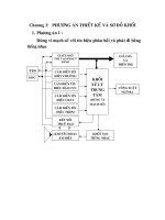
2. FUNCTION OF MAIN COMPONENT (w/ MEMORY)
(a) The following functions are available.
3. SYSTEM OPERATION
(a) The front power seats adjustment and position
memory are shown in the chart below.
In the memory function, the memory switch
operation signal is transferred from the power
window regulator switch assembly (power window
master switch) to the position control ECU and
switch assembly (power seat control switch and
ECU) via the multiplex communication line. Then,
either the seat position is stored in memory or the
previously stored seat position is recalled to set the
appropriate seat position.
Components Function
Seat slide motor
Slides the driver side seat back and forth based on signals from the position control ECU and switch
assembly (power seat control switch and ECU).
Seat reclining motor
Reclines the driver side seat back and forth based on signals from the position control ECU and switch
assembly (power seat control switch and ECU).
Seat front vertical motor
Moves the front part of the driver side seat cushion up and down based on signals from the position
control ECU and switch assembly (power seat control switch and ECU).
Seat lifter motor
Moves the driver side seat cushion up and down based on signals from the position control ECU and
switch assembly (power seat control switch and ECU). This motor operates, and driver side seat rear
vertical raises and lowers, and driver side seat rear vertical raises and lowers.
Set switch
Memory switch
When the set and memory switches are pressed simultaneously, SET, 1 or 2 switch signal is input to the
power window regulator switch assembly (power window master switch) and sends the seat memory
switch signal via the multiplex communication system.
When only the memory switch is pressed, SET, 1 or 2 switch signal is input to power window regulator
switch assembly (power window master switch) and driver side seat position changes according to
memory.
Seat Adjustment Function Driver Side Front Passenger Side
Slide Power and memory Power
Reclining Power and memory Power
Front Vertical Power and memory Power
Lifter Power and memory Power
Lumbar Support Power -
SE–6
SEAT – FRONT POWER SEAT CONTROL SYSTEM (w/ Memory)
SE
HOW TO PROCEED WITH
TROUBLESHOOTING
HINT:
• Use this procedure to troubleshoot the front power seat
control system.
• The intelligent tester should be used in steps 3 and 5.
NEXT
NEXT
(a) Use the intelligent tester to check for normal function of
the multiplex communication system.
(1) (Position control ECU and switch assembly (power
seat control switch and ECU) not connected,
communication line malfunctioning) If no code is
output, proceed to A.
(2) (Position control ECU and switch assembly (power
seat control switch and ECU) not connected,
communication line malfunctioning) If any code is
output, proceed to B.
B
A
(a) If the fault is not listed on the problem symptoms table,
proceed to A.
(b) If the fault is listed on the problem symptoms table,
proceed to B.
B
A
(a) DATA LIST/ACTIVE TEST (See page SE-11).
(1) Inspection with the intelligent tester (DATA LIST).
1
VEHICLE BROUGHT TO WORKSHOP
2
CUSTOMER PROBLEM ANALYSIS CHECK AND PROBLEM SYMPTOM CHECK
3
CHECK COMMUNICATION FUNCTION OF MULTIPLEX COMMUNICATION SYSTEM
(BEAN)
Go to MULTIPLEX COMMUNICATION
SYSTEM
4
PROBLEM SYMPTOMS TABLE
Go to step 6
5
OVERALL ANALYSIS AND TROUBLESHOOTING
SEAT – FRONT POWER SEAT CONTROL SYSTEM (w/ Memory)
SE–7
SE
(2) Inspection with the intelligent tester (ACTIVE
TEST).
(b) Terminals of ECU (See page SE-8).
(c) Inspection.
NEXT
NEXT
NEXT
6
ADJUST, REPAIR OR REPLACE
7
CONFIRMATION TEST
END
SE–8
SEAT – FRONT POWER SEAT CONTROL SYSTEM (w/ Memory)
SE
PROBLEM SYMPTOMS TABLE
HINT:
• Inspect the fuse and relay before confirming the suspected
areas in the table below.
• Inspect each suspected area in numerical order for the
corresponding symptom.
If the malfunction still exists after checking and confirming
that all circuits and components are normal, replace the ECU.
1. FRONT POWER SEAT CONTROL SYSTEM (w/o MEMORY)
2. FRONT POWER SEAT CONTROL SYSTEM (w/ MEMORY)
Symptom Suspected area See page
Power seat does not operate (slide, front vertical, lifter,
reclining).
1. P/SEAT fuse -
2. Power seat switch SE-75
3. Wire harness or connector -
Slide operation function only does not operate.
1. Power seat switch SE-75
2. Front seat frame with adjuster (LH side slide motor) SE-77
3. Front seat frame with adjuster (RH side slide motor) SE-78
4. Wire harness or connector -
Front vertical operation function only does not operate.
1. Power seat switch SE-75
2. Front seat frame with adjuster (LH side front vertical motor) SE-77
3. Front seat frame with adjuster (RH side front vertical motor) SE-78
4. Wire harness or connector -
Lifter operation function only does not operate.
1. Power seat switch SE-75
2. Front seat frame with adjuster (LH side lifter motor) SE-77
3. Front seat frame with adjuster (RH side lifter motor) SE-78
4. Wire harness or connector -
Reclining operation function only does not operate.
1. Power seat switch SE-75
2. Front seat frame with adjuster (LH side reclining motor) SE-77
3. Front seat frame with adjuster (RH side reclining motor) SE-78
4. Wire harness or connector -
Lumbar support operation function only does not
operate (Driver side only).
1. Front power seat lumbar switch SE-80
2. Lumbar support adjuster assembly SE-81
3. Wire harness or connector -
Symptom Suspected area See page
Power seat does not operate (manual or memorized
position).
1. ECU power source circuit SE-24
2. Position control ECU and switch assembly (power seat
control switch and ECU)
SE-39
One of the power seat functions does not operate
(manual or memorized position).
1. Power seat motor circuit SE-16
2. Position control ECU and switch assembly (power seat
control switch and ECU)
SE-39
One or all manual seat functions do not operate
(memorized positions OK).
1. Position control ECU and switch assembly (power seat
control switch and ECU)
SE-39
Memory function does not operate.
1. Memory switch circuit SE-20
2. Multiplex communication system MP-6
3. Position control ECU and switch assembly (power seat
control switch and ECU)
SE-39
No memory functions operate or all memory functions
operate briefly and then stop (manual functions OK).
1. ECU power source circuit SE-24
2. Position control ECU and switch assembly (power seat
control switch and ECU)
SE-39
One memory function does not operate or operates
briefly and then stops (manual functions OK).
1. Front seat frame with adjuster (power seat motor) SE-77
2. Position control ECU and switch assembly (power seat
control switch and ECU)
SE-39
SEAT – FRONT POWER SEAT CONTROL SYSTEM (w/ Memory)
SE–9
SE
TERMINALS OF ECU
1. POSITION CONTROL ECU AND SWITCH ASSEMBLY
(POWER SEAT CONTROL SWITCH AND ECU)
(a) Disconnect the P32 and P33 connectors.
(b) Check the voltage of each terminal of the wire
harness side connectors.
If the result is not as specified, there may be a
malfunction in the wire harness side.
(c) Check the resistance of each terminal of the wire
harness side connectors.
If the result is not as specified, there may be a
malfunction in the wire harness side.
(d) Reconnect the P32 and P33 connectors.
(e) Check the voltage of each terminal of the
connectors.
Connector Front View:
P33
P32
B066387E01
Symbols (Terminal No.) Wiring Color Terminal Description Condition Specified Condition
IG(P32-4) - GND(P33-1) Y - W-B Ignition switch
Ignition switch off →
ignition switch on
Below 1 V → 10 to 14 V
SYSB(P32-8) - GND(P33-
1)
GR - W-B Power source Always 10 to 14 V
+B(P33-5) - GND(P33-1) LG - W-B Battery Always 10 to 14 V
Symbols (Terminal No.) Wiring Color Terminal Description Condition Specified Condition
GND(P33-1) - Body
ground
W-B - Body ground Ground Always Below 1 Ω
Symbols (Terminal No.) Wiring Color Terminal Description Condition Specified Condition
MPX1(P32-1) - GND(P33-
1)
W - W-B
Multiplex communication
signal circuit
Ignition switch on Pulse generation
SLD+(P33-2) - GND(P33-
1)
L - W-B
Sliding motor signal
(Forward)
Seat moving forward using
sliding switch → Other
conditions
10 to 14 V → Below 1 V
SLD-(P33-3) - GND(P33-
1)
Y - W-B
Sliding motor signal
(Rearward)
Seat moving rearward
using sliding switch →
Other conditions
10 to 14 V → Below 1 V
FRV-(P33-4) - GND(P33-
1)
B - W-B
Front vertical motor signal
(Downward)
Seat cushion front portion
lowering using front
vertical switch → Other
conditions
10 to 14 V → Below 1 V
FRV+(P33-6) - GND(P33-
1)
G - W-B
Front vertical motor signal
(Upward)
Seat cushion front portion
rising using front vertical
switch → Other conditions
10 to 14 V → Below 1 V
LFT+(P33-7) - GND(P33-
1)
W - W-B
Lifter motor signal
(Upward)
Seat rising using lifter
switch → Other conditions
10 to 14 V → Below 1 V
SE–10
SEAT – FRONT POWER SEAT CONTROL SYSTEM (w/ Memory)
SE
If the result is not as specified, the position control
ECU and switch assembly may be malfunctioning.
2. POWER WINDOW REGULATOR SWITCH ASSEMBLY
(POWER WINDOW MASTER SWITCH)
(a) Disconnect the P22 connector.
(b) Check the voltage of each terminal of the wire
harness side connectors.
If the result is not as specified, there may be a
malfunction in the wire harness side.
(c) Check the resistance of each terminal of the wire
harness side connector.
If the result is not as specified, there may be a
malfunction in the wire harness side.
(d) Reconnect the P22 connector.
(e) Check the voltage of each terminal of the
connectors.
RCL+(P33-8) - GND(P33-
1)
P - W-B
Reclining motor signal
(Forward)
Seatback moving forward
using reclining switch →
Other conditions
10 to 14 V → Below 1 V
LFT-(P33-9) - GND(P33-1) V - W-B
Lifter motor signal
(Downward)
Seat lowering using lifter
switch → Other conditions
10 to 14 V → Below 1 V
RCL-(P33-10) - GND(P33-
1)
BR - W-B
Reclining motor signal
(Rearward)
Seatback moving
rearward using reclining
switch → Other conditions
10 to 14 V → Below 1 V
Symbols (Terminal No.) Wiring Color Terminal Description Condition Specified Condition
19
20 12 11
18 17 16 15 14 13
9
10 2 1
876543
Connector Front View:
P22
B115721E02
Symbols (Terminal No.) Wiring Color Terminal Description Condition Specified Condition
CPUB(P22-9) - GND(P22-
2)
L-B - W-B Power source Always 10 to 14 V
BDR(P22-10) - GND(P22-
2)
G - W-B
Power window motor
power source
Always 10 to 14 V
SIG(P22-20) - GND(P22-
2)
BR - W-B Ignition switch signal
Ignition switch off →
ignition switch on
Below 1 V → 10 to 14 V
Symbols (Terminal No.) Wiring Color Terminal Description Condition Specified Condition
GND(P22-2) - Body
ground
W-B - Body ground Ground Always Below 1 Ω
Symbols (Terminal No.) Wiring Color Terminal Description Condition Specified Condition
MM(P22-3) - GND(P22-2) LG - W-B SET switch signal
SET switch is not pushed
→ pushed
10 to 14 V → Below 1 V
M1(P22-13) - GND(P22-2) G - W-B SW1 switch signal
SW1 switch is not pushed
→ pushed
10 to 14 V → Below 1 V
M2(P22-17) - GND(P22-2) V - W-B SW2 switch signal
SW2 switch is not pushed
→ pushed
10 to 14 V → Below 1 V
SEAT – FRONT POWER SEAT CONTROL SYSTEM (w/ Memory)
SE–11
SE
If the result is not as specified, the power window
regulator switch assembly may be malfunctioning.
SE–12
SEAT – FRONT POWER SEAT CONTROL SYSTEM (w/ Memory)
SE
DIAGNOSIS SYSTEM
1. DESCRIPTION
(a) Front power seat control system data can be read
through the Data Link Connector 3 (DLC3) of the
vehicle. When the system seems to be
malfunctioning, use the intelligent tester to check for
malfunctions and perform repairs.
2. CHECK DLC3
(a) The vehicle uses ISO 15765-4 communication
protocol. The terminal arrangement of the DLC3
complies with SAE J1962 and matches the ISO
15765-4 format.
If the result is not as specified, the DLC3 may have
a malfunction. Repair or replace the wire harness
and connector.
HINT:
Connect the cable of the intelligent tester to the
DLC3, turn the ignition switch on and attempt to use
the tester. If the screen displays a communication
error message, a problem exists on the vehicle side
or the tester side.
• If communication is normal when the tester is
connected to another vehicle, inspect the DLC3
of the original vehicle.
• If communication is still not possible when the
tester is connected to another vehicle, the
problem is probably in the tester itself. Consult
the Service Department listed in the tester's
instruction manual.
3. INSPECT BATTERY VOLTAGE
(a) Check the battery voltage.
Voltage:
11 to 14 V
If the voltage is below 11 V, recharge or replace the
battery before proceeding.
12345678
910111213 1514 16
CG
SG
SIL
BAT
A082779E09
Symbols (Terminal No.) Terminal Description Condition Specified Condition
SIL(7) - SG(5) Bus "+" line During transmission Pulse generation
CG(4) - Body ground Chassis ground Always Below 1 Ω
SG(5) - Body ground Signal ground Always Below 1 Ω
BAT(16) - Body ground Battery positive Always 11 to 14 V
SEAT – FRONT POWER SEAT CONTROL SYSTEM (w/ Memory)
SE–13
SE
DATA LIST / ACTIVE TEST
1. DATA LIST
HINT:
Using the intelligent tester's DATA LIST allows the status
of a switch, sensor, actuator and other items to be read
without removing any parts. Reading the DATA LIST
early in troubleshooting is one way to save time.
(a) Connect the intelligent tester (with CAN VIM) to the
DLC3.
(b) Turn the ignition switch on.
(c) Read the DATA LIST.
D_SEAT (Position control ECU and switch assembly)
Item
Measurement Item/Range
(Display)
Normal Condition Diagnostic Note
RECLIN SW REAR
Reclining switch signal
(Rearward)/ ON or OFF
ON: Reclining switch (Rearward) is ON
OFF: Reclining switch (Rearward) is OFF
-
RECLIN SW FRONT
Reclining switch signal (Forward)/
ON or OFF
ON: Reclining switch (Forward) is ON
OFF: Reclining switch (Forward) is OFF
-
F VTCL SW DOWN
Front vertical switch signal
(Downward)/ ON or OFF
ON: Front vertical switch (Downward) is ON
OFF: Front vertical switch (Downward) is
OFF
-
F VTCL SW UP
Front vertical switch signal
(Upward)/ ON or OFF
ON: Front vertical switch (Upward) is ON
OFF: Front vertical switch (Upward) is OFF
-
LIFTER SW DOWN
Lifter switch signal (Downward)/
ON or OFF
ON: Lifter switch (Downward) is ON
OFF: Lifter switch (Downward) is OFF
-
LIFTER SW UP
Lifter switch signal (Upward)/ ON
or OFF
ON: Lifter switch (Upward) is ON
OFF: Lifter switch (Upward) is OFF
-
SLIDE SW REAR
Sliding switch signal (Rearward)/
ON or OFF
ON: Sliding switch (Rearward) is ON
OFF: Sliding switch (Rearward) is OFF
-
SLIDE SW FRONT
Sliding switch signal (Forward)/
ON or OFF
ON: Sliding switch (Forward) is ON
OFF: Sliding switch (Forward) is OFF
-
POWER VOLTAGE
Power supply for position control
ECU and switch assembly/ MIN:
0 V, MAX: 19.89 V
Within range from 11 to 14 V -
IG SW
Ignition switch position/ ON or
OFF
ON: Ignition switch is ON
OFF: Ignition switch is OFF
-
KEY UNLOCK SW
Key unlock warning switch signal/
ON or OFF
ON: Key is in ignition key cylinder
OFF: Key is not in ignition key cylinder
-
D-DOOR WARN SW
Door courtesy light switch signal/
ON or OFF
ON: Driver side door is open
OFF: Driver side door is closed
-
PNP SW
Shift lever position P signal/ ON
or OFF
ON: Shift lever in P position
OFF: Shift lever in any position except P
-
M2 SW
Seat memory M2 switch signal/
ON or OFF
ON: Seat memory M2 switch is ON
OFF: Seat memory M2 switch is OFF
-
M1 SW
Seat memory M1 switch signal/
ON or OFF
ON: Seat memory M1 switch is ON
OFF: Seat memory M1 switch is OFF
-
SET SW
Seat memory set switch signal/
ON or OFF
ON: Seat memory set switch is ON
OFF: Seat memory set switch is OFF
-
SLIDE POS
Seat sliding position/ MIN: -4096,
MAX: 4096
Within range from -4096 to 4096 -
RECLIN POS
Seatback position/ MIN: -4096,
MAX: 4096
Within range from -4096 to 4096 -
F VTCL POS
Seat front vertical position/ MIN: -
4096, MAX: 4096
Within range from -4096 to 4096 -
LIFTER POS
Seat lifter position/ MIN: -4096,
MAX: 4096
Within range from -4096 to 4096 -
SE–14
SEAT – FRONT POWER SEAT CONTROL SYSTEM (w/ Memory)
SE
MEM M1 SW
Driving position memorized with
seat memory switch M1/ MEM or
NOT MEM
MEM: Memorized
NOT MEM: Not memorized
-
MEM M2 SW
Driving position memorized with
seat memory switch M2/ MEM or
NOT MEM
MEM: Memorized
NOT MEM: Not memorized
-
SEAT MEM M1
Seat position memorized with
seat memory switch M1/ MEM or
NOT MEM
MEM: Memorized
NOT MEM: Not memorized
-
SEAT MEM M2
Seat position memorized with
seat memory switch M2/ MEM or
NOT MEM
MEM: Memorized
NOT MEM: Not memorized
-
D-MIRR MEM 1
Driver side mirror position
memorized with seat memory
switch M1/ MEM or NOT MEM
MEM: Memorized
NOT MEM: Not memorized
-
D-MIRR MEM 2
Driver side mirror position
memorized with seat memory
switch M2/ MEM or NOT MEM
MEM: Memorized
NOT MEM: Not memorized
-
P-MIRR MEM 1
Front passenger side mirror
position memorized with seat
memory switch M1/ MEM or NOT
MEM
MEM: Memorized
NOT MEM: Not memorized
-
P-MIRR MEM 2
Front passenger side mirror
position memorized with seat
memory switch M2/ MEM or NOT
MEM
MEM: Memorized
NOT MEM: Not memorized
-
SLIDE MEM POS 1
Seat sliding position memorized
with seat memory switch M1/
MIN: -4096, MAX: 4096
Within range from -4096 to 4096 -
RECLN MEM POS 1
Seatback position memorized
with seat memory switch M1/
MIN: -4096, MAX: 4096
Within range from -4096 to 4096 -
F VTCL MEM POS 1
Front vertical position memorized
with seat memory switch M1/
MIN: -4096, MAX: 4096
Within range from -4096 to 4096 -
LIFTER MEM POS 1
Lifter position memorized with
seat memory switch M1/ MIN: -
4096, MAX: 4096
Within range from -4096 to 4096 -
SLIDE MEM POS 2
Seat sliding position memorized
with seat memory switch M2/
MIN: -4096, MAX: 4096
Within range from -4096 to 4096 -
RECLN MEM POS 2
Seatback position memorized
with seat memory switch M2/
MIN: -4096, MAX: 4096
Within range from -4096 to 4096 -
F VTCL MEM POS 2
Front vertical position memorized
with seat memory switch M2/
MIN: -4096, MAX: 4096
Within range from -4096 to 4096 -
LIFTER MEM POS 2
Lifter position memorized with
seat memory switch M2/ MIN: -
4096, MAX: 4096
Within range from -4096 to 4096 -
D-MIRR MEM POS 1
Driver side mirror position
memorized with seat memory
switch M1/ MIN: 0, MAX: 65535
Within range from 0 to 65535 -
P-MIRR MEM POS 1
Front passenger side mirror
position memorized with seat
memory switch M1/ MIN: 0, MAX:
65535
Within range from 0 to 65535 -
D-MIRR MEM POS 2
Driver side mirror position
memorized with seat memory
switch M2/ MIN: 0, MAX: 65535
Within range from 0 to 65535 -
Item
Measurement Item/Range
(Display)
Normal Condition Diagnostic Note
SEAT – FRONT POWER SEAT CONTROL SYSTEM (w/ Memory)
SE–15
SE
2. ACTIVE TEST
HINT:
Using the intelligent tester's ACTIVE TEST allows the
relay, VSV, actuator, and other items to be operated
without removing any parts. Reading the ACTIVE TEST
early in troubleshooting is one way to save time. The
DATA LIST can be displayed during the ACTIVE TEST.
(a) Connect the intelligent tester (with CAN VIM) to the
DLC3.
(b) Turn the ignition switch on.
(c) Perform the ACTIVE TEST by following the
directions on the tester screen.
D_SEAT (Position control ECU and switch assembly)
P-MIRR MEM POS 2
Front passenger side mirror
position memorized with seat
memory switch M2/ MIN: 0, MAX:
65535
Within range from 0 to 65535 -
Item
Measurement Item/Range
(Display)
Normal Condition Diagnostic Note
Item Test Details Diagnostic Note
RECLINING
Test detail: reclining operation FRONT/REAR
Vehicle condition: stopped
-
F VERTICAL
Test detail: front vertical operation UP/DOWN
Vehicle condition: stopped
-
LIFTER
Test detail: lifter operation UP/DOWN
Vehicle condition: stopped
-
SLIDE
Test detail: sliding operation UP/DOWN
Vehicle condition: stopped
-
SE–16
SEAT – FRONT POWER SEAT CONTROL SYSTEM (w/ Memory)
SE
ON-VEHICLE INSPECTION
1. CHECK POWER SEAT FUNCTION
(a) Check the basic functions.
(1) Operate the power seat switches and check the
following seat functions:
• Sliding
• Reclining
• Front vertical
•Lifter
• Lumbar support (Driver side seat only)
2. CHECK POWER SEAT MOTOR ASSEMBLY (SLIDING,
FRONT VERTICAL, LIFTER AND RECLINING
FUNCTIONS)
(a) Inspect the PTC operation inside the power seat
motor.
NOTICE:
The inspection should be performed with the
seat installed in the vehicle.
(1) Move the seat to any of the maximum position
by operating the power seat switch, and keep
the seat there for approximately 60 seconds.
(2) Try to move the power seat beyond the
maximum position using the power seat switch.
Measure the time needed for shutting off the
electrical current after the lumbar support stops
moving. (motor operation sound will stop,
inspection of current shut-off).
Standard:
4 to 90 seconds
(3) Release the power seat switch, and wait for
approximately 60 seconds.
(4) Operate the power seat switch to move the
seat to the opposite position and check that the
motor operates.
3. CHECK LUMBAR SUPPORT ADJUSTER ASSEMBLY
(a) Inspect the PTC operation inside the power seat
motor.
NOTICE:
The inspection should be performed with the
seat installed in the vehicle.
(1) Move the lumbar support to either the foremost
or rearmost position by operating the lumbar
support switch, and keep it there for
approximately 60 seconds.
(2) Try to move the lumbar support beyond the
maximum position using the switch. Measure
the time needed for shutting off the electrical
current after the lumbar support stops moving.
(motor operation sound will stop, inspection of
current shut-off).
Standard:
4 to 90 seconds
Reclining Function
Sliding Function
Lifter Function
Lumbar support
Function
Front Vertical
Function
B113023E01
SEAT – FRONT POWER SEAT CONTROL SYSTEM (w/ Memory)
SE–17
SE
(3) Release the lumbar support switch, and wait for
approximately 60 seconds.
(4) Operate the lumbar support switch to move the
lumbar support to the opposite position and
check that the motor operates.
4. CHECK MEMORY AND REACTIVATION FUNCTION
(w/ MEMORY)
(a) Turn the ignition switch on and move the shift lever
into the P position.
(b) Move the seat into the foremost position and
uppermost position using each seat switch.
(c) Check that the buzzer sounds for 0.5 seconds. The
seat position is recorded when the SW1 switch is
pressed while also pressing the SET switch.
(d) Move the seat out of the foremost position and
uppermost position using each seat switch.
(e) Check that the buzzer sounds for 0.5 seconds. The
seat position is recorded when the SW2 switch is
pressed while also pressing the SET switch.
(f) Check that the buzzer sounds for 0.1 seconds and
the seat automatically moves into the foremost
position and uppermost position (SET positions)
when the SW1 switch is pressed.
(g) Check that the buzzer sounds for 0.1 seconds and
the seat automatically moves out of the foremost
position and uppermost position (SET positions)
when the SW2 switch is pressed.
(h) Check that the seat automatically moves into the
SET position when the SW1 or SW2 switch is
pressed within 30 seconds after the ignition switch
is turned off, the key is pulled out from the key
cylinder and the driver side door is opened.
(i) Move the seat either forward or back as far as the
seat will move, and disconnect the negative terminal
of the battery while the memory switch is pressed.
Then leave the seat at the position for 3 minutes to
erase the seat position memory.
(j) Move the seat into all the maximum positions (front/
rear and up/down) using each seat switch.
(k) Check that the seat does not move (the seat
position is not recorded) by performing the following
steps while pressing the SET switch. Press either
the SW1 switch or the SW2 switch after pressing
SW1 and SW2 at the same time.
Seat Memory
Switch
SW1
SW2
SET
B068338E01
SE–18
SEAT – FRONT POWER SEAT CONTROL SYSTEM (w/ Memory)
SE
DESCRIPTION
When the power seat control switch is operated, a command signal is sent to the position control ECU
and switch assembly (power seat control switch and ECU). The front power seat switch then controls the
appropriate seat motor as needed. This memory system does not use a seat position sensor. The seat
position is detected by counting pulses that are output when the motor turns. If there is no pulse output
from the motor, the motor will stop operating. The position control ECU and switch assembly (power seat
control switch and ECU) is designed so that any malfunction of the seat memory system will not interfere
with manual seat control.
If the position control ECU and switch assembly (power seat control switch and ECU) detects a low motor
speed, abnormal activity, or sudden motor current fluctuation, the system will stop the motor. If the motor
operates continuously for 120 seconds or more, the system will stop the motor until the switch is turned on
again.
Power Seat Motor Circuit
SEAT – FRONT POWER SEAT CONTROL SYSTEM (w/ Memory)
SE–19
SE
WIRING DIAGRAM
(a) Connect the intelligent tester (with CAN VIM) to the
DLC3.
(b) Turn the ignition switch on.
(c) Perform the ACTIVE TEST by following the directions on
the tester screen.
D_SEAT (Position control ECU and switch assembly)
1
PERFORM ACTIVE TEST BY INTELLIGENT TESTER
C
Power Seat Motor (Slide Control)
SLD+
SLD-
LFT+
LFT-
RCL+
FRV+
FRV-
RCL-
Power Seat Motor (Lifter Control)
Power Seat Motor (Reclining Control)
Power Seat Motor (Front Vertical Control)
(Power Seat Control
Switch and ECU)
Position Control ECU
and Switch Assembly
B111872E01
Item Test Details Diagnostic Note
RECLINING
Test detail: reclining operation FRONT/REAR
Vehicle condition: stopped
-
SE–20
SEAT – FRONT POWER SEAT CONTROL SYSTEM (w/ Memory)
SE
OK:
Each power seat motor operates.
NG
OK
(a) Inspect the power seat motor (See page SE-77).
OK:
The power seat motor operates.
NG
OK
F VERTICAL
Test detail: front vertical operation UP/DOWN
Vehicle condition: stopped
-
LIFTER
Test detail: lifter operation UP/DOWN
Vehicle condition: stopped
-
SLIDE
Test detail: sliding operation UP/DOWN
Vehicle condition: stopped
-
Item Test Details Diagnostic Note
Go to step 2
PROCEED TO NEXT CIRCUIT INSPECTION SHOWN IN PROBLEM SYMPTOMS TABLE
2
INSPECT FRONT SEAT ADJUSTER SUB-ASSEMBLY (POWER SEAT MOTOR)
REPLACE FRONT SEAT ADJUSTER SUB-
ASSEMBLY (POWER SEAT MOTOR)
SEAT – FRONT POWER SEAT CONTROL SYSTEM (w/ Memory)
SE–21
SE
(a) Disconnect the position control ECU and switch
assembly connector and power seat motor connectors.
(b) Measure the resistance according to the value(s) in the
table below.
Resistance
NG
OK
3
CHECK HARNESS AND CONNECTOR (POSITION CONTROL ECU AND SWITCH
ASSEMBLY - POWER SEAT MOTOR)
Position Control ECU and Switch
Assembly Connector
Wire Harness Rear View:
Power Seat Motor Connector
P34
Wire Harness Front View:
P35
P37 P38
P33
2(SLD+)
3(SLD-)
4(FRV-)
6(FRV+)
7(LFT+)
8(RCL+)
9(LFT-)
10(RCL-)
B112268E01
Tester Connection Condition Specified Condition
P33-2(SLD+) - P38-1 Always Below 1 Ω
P33-3(SLD-) - P38-2 Always Below 1 Ω
P33-4(FRV-) - P34-2 Always Below 1 Ω
P33-6(FRV+) - P34-1 Always Below 1 Ω
P33-7(LFT+) - P35-2 Always Below 1 Ω
P33-9(LFT-) - P35-1 Always Below 1 Ω
P33-8(RCL+) - P37-2 Always Below 1 Ω
P33-10(RCL-) - P37-1 Always Below 1 Ω
P33-2(SLD+) - Body
ground
Always 10 kΩ or higher
P33-3(SLD-) - Body
ground
Always 10 kΩ or higher
P33-4(FRV-) - Body
ground
Always 10 kΩ or higher
P33-6(FRV+) - Body
ground
Always 10 kΩ or higher
P33-7(LFT+) - Body
ground
Always 10 kΩ or higher
P33-9(LFT-) - Body
ground
Always 10 kΩ or higher
P33-8(RCL+) - Body
ground
Always 10 kΩ or higher
P33-10(RCL-) - Body
ground
Always 10 kΩ or higher
REPAIR OR REPLACE HARNESS OR
CONNECTOR
PROCEED TO NEXT CIRCUIT INSPECTION SHOWN IN PROBLEM SYMPTOMS TABLE
SE–22
SEAT – FRONT POWER SEAT CONTROL SYSTEM (w/ Memory)
SE
DESCRIPTION
The seat memory switch sends signals to the power window regulator switch assembly (power window
master switch) via the multiplex communication system to memorize a given seat position. This memory
system does not use a position sensor. The seat position is detected by counting pulses that are output
when the motor turns. If there is no pulse output from the motor, the motor will stop operating. The seat
memory switch is later used to send signals to the front power seat switch to return the seat to one of the
memorized positions.
The power seat memory operation can be performed only when the ignition switch is on and the shift lever
is in the P position.
WIRING DIAGRAM
(a) Connect the intelligent tester (with CAN VIM) to the
DLC3.
(b) Turn the ignition switch on.
Driving Position Memory Switch Circuit (w/ Memory)
1
READ VALUE OF INTELLIGENT TESTER
C
Position Control ECU
and Switch Assembly
Power Window Regulator
Switch Assembly
Multiplex Network
Communication Circuit
(Power Window
Master Switch)
(Power Seat Control
Switch and ECU)
(Driving Position
Memory Switch)
Seat Memory Switch
MPX1
MPX1
MPX2
MMRY
1
2
E
M1
MM
M2
B111873E01
SEAT – FRONT POWER SEAT CONTROL SYSTEM (w/ Memory)
SE–23
SE
(c) Read the DATA LIST.
D_SEAT (Position control ECU and switch assembly)
OK:
Condition status can be displayed.
NG
OK
(a) Remove the seat memory switch.
(b) Measure the resistance according to the value(s) in the
table below.
Resistance
NG
OK
Item
Measurement Item/Range
(Display)
Normal Condition Diagnostic Note
M2 SW
Seat memory M2 switch signal/
ON or OFF
ON: Seat memory M2 switch is
ON
OFF: Seat memory M2 switch is
OFF
-
M1 SW
Seat memory M1 switch signal/
ON or OFF
ON: Seat memory M1 switch is
ON
OFF: Seat memory M1 switch is
OFF
-
SET SW
Seat memory set switch signal/
ON or OFF
ON: Seat memory set switch is
ON
OFF: Seat memory set switch is
OFF
-
Go to step 2
PROCEED TO NEXT CIRCUIT INSPECTION SHOWN IN PROBLEM SYMPTOMS TABLE
2
INSPECT SEAT MEMORY SWITCH (DRIVING POSITION MEMORY SWITCH)
SW1
Seat Memory Switch:
1
2
E
SW2
SET
MMRY
B068340E01
Tester Connection Switch Position Specified Condition
1(E) - 2(MMRY)
SET switch ON
(pushed)
Below 1 Ω
1(E) - 2(MMRY)
SET switch OFF (not
pushed)
10 kΩ or higher
1(E) - 4(1)
SW1 switch ON
(pushed)
Below 1 Ω
1(E) - 4(1)
SW1 switch OFF (not
pushed)
10 kΩ or higher
1(E) - 3(2)
SW2 switch ON
(pushed)
Below 1 Ω
1(E) - 3(2)
SW2 switch OFF (not
pushed)
10 kΩ or higher
REPLACE SEAT MEMORY SWITCH
(DRIVING POSITION MEMORY SWITCH)
SE–24
SEAT – FRONT POWER SEAT CONTROL SYSTEM (w/ Memory)
SE
(a) Measure the voltage according to the value(s) in the
table below.
Voltage
NG
OK
(a) Disconnect the power window regulator switch assembly
connector.
(b) Measure the resistance according to the value(s) in the
table below.
Resistance
NG
3
CHECK HARNESS AND CONNECTOR (SEAT MEMORY SWITCH CIRCUIT)
Wire Harness Rear View:
D15
1(E)
3(2)
4(1)
2(MMRY)
B111886E01
Tester Connection Switch Position Specified Condition
D15-2(MMRY) - D15-1(E) Ignition switch on 10 to 14 V
D15-3(2) - D15-1(E) Ignition switch on 10 to 14 V
D15-4(1) - D15-1(E) Ignition switch on 10 to 14 V
Go to step 4
PROCEED TO NEXT CIRCUIT INSPECTION SHOWN IN PROBLEM SYMPTOMS TABLE
4
CHECK HARNESS AND CONNECTOR (POWER WINDOW REGULATOR SWITCH
ASSEMBLY - SEAT MEMORY SWITCH)
1(E)
3(2)
4(1)
D15
2(MMRY)
Seat Memory Switch Connector
Wire Harness Rear View:
Power Window Regulator
Switch Connector
Wire Harness Rear View:
P22
3(MM)
17(M2)
13(M1)
B111885E01
Tester Connection Switch Position Specified Condition
D15-1(E) - Body ground Always Below 1 Ω
D15-2(MMRY) - P22-
3(MM)
Always Below 1 Ω
D15-3(2) - P22-17(M2) Always Below 1 Ω
D15-4(1) - P22-13(M1) Always Below 1 Ω
D15-2(MMRY) - Body
ground
Always 10 kΩ or higher
D15-3(2) - Body ground Always 10 kΩ or higher
D15-4(1) - Body ground Always 10 kΩ or higher
REPAIR OR REPLACE HARNESS OR
CONNECTOR
SEAT – FRONT POWER SEAT CONTROL SYSTEM (w/ Memory)
SE–25
SE
OK
REPLACE POWER WINDOW REGULATOR SWITCH ASSEMBLY (POWER WINDOW MASTER
SWITCH)