Nghiên cứu điều khiển động cơ IPM
Bạn đang xem bản rút gọn của tài liệu. Xem và tải ngay bản đầy đủ của tài liệu tại đây (4.42 MB, 10 trang )
IEEE
TRANSACTIONS
ON
INDUSTRY
APPLICATIONS,
VOL.
IA-22,
NO.
4,
JULY/AUGUST
1986
Interior
Permanent-Magnet
Synchronous
Motors
for
Adjustable-Speed
Drives
THOMAS
M.
JAHNS,
MEMBER,
IEEE,
GERALD
B.
KLIMAN,
SENIOR
MEMBER,
IEEE,
AND
THOMAS
W.
NEUMANN
Abstract-Interior
permanent-magnet
(IPM)
synchronous
motors
possess
special
features
for
adjustable-speed
operation
which
distinguish
them
from
other
classes
of
ac
machines.
They
are
robust
high
power-
density
machines
capable
of
operating
at
high
motor
and
inverter
efficiencies
over
wide
speed
ranges,
including
considerable
ranges
of
constant-power
operation.
The
magnet
cost
is
minimized
by
the
low
magnet
weight
requirements
of
the
IPM
design.
The
impact
of
the
buried-
magnet
configuration
on
the
motor's
electromagnetic
characteristics
is
discussed.
The
rotor
magnetic
circuit
saliency
preferentially
increases
the
quadrature-axis
inductance
and
introduces
a
reluctance
torque
term
into
the
IPM
motor's
torque
equation.
The
electrical
excitation
requirements
for
the
IPM
synchronous
motor
are
also
discussed.
The
control
of
the
sinusoidal
phase
currents
in
magnitude
and
phase
angle
with
respect
to
the
rotor
orientation
provides
a
means
for
achieving
smooth
responsive
torque
control.
A
basic
feedforward
algorithm
for
executing
this
type
of
current
vector
torque
control
is
discussed,
including
the
implications
of
current
regulator
saturation
at
high
speeds.
The
key
results
are
illustrated
using
a
combination
of
simulation
and
prototype
IPM
drive
measure-
ments.
I.
INTRODUCTION
A.
Background
pERMANENT-magnet
(PM)
synchronous
motors
are
attracting
growing
international
attention
for
a
wide
variety
of
industrial
applications,
ranging
from
general-
purpose
line-start
pump/fan
drives
[1]
to
high-performance
machine
tool
servos
[2].
The
attractive
power-density
and
efficiency
characteristics
exhibited
by
these
motors
as
a
class
are
major
factors
responsible
for
generating
this
interest.
The
recent
announcements
of
more
powerful
and
cost-effective
permanent
magnet
materials
are
serving
to
accelerate
these
motor
development
efforts
[3].
The
large
majority
of
commercially
available
PM
synchro-
nous
motors
are
constructed
with
the
permanent
magnets
mounted
on
the
periphery
of
the
steel
rotor
core,
exposing
their
surfaces
magnetically,
and
sometimes
physically,
to
the
Paper
IPCSD
85-51,
approved
by
the
Fractional
and
Integral
Horse
Power
Subcommittee
of
the
Industrial
Drives
Committee
of
the
IEEE
Industry
Applications
Society
for
presentation
at
the
1985
Industry
Applications
Society
Annual
Meeting,
Toronto,
ON,
October
6-11.
Manuscript
released
for
publication
December
21,
1985.
T.
M.
Jahns
is
with
the
General
Electric
Company,
Corporate
Research
and
Development
Center,
P.O.
Box
43,
Room
37-325,
Schenectady,
NY
12301.
G.
B.
Kliman
is
with
the
General
Electric
Company,
Corporate
Research
and
Development
Center,
P.O.
Box
43,
Room
37-380,
Schenectady,
NY
12301.
T.
W.
Neumann
was
with
the
General
Electric
Company,
Corporate
Research
and
Development
Center,
Schenectady,
NY.
He
is
now
with
the
General
Electric
Company
Motor
Technology
Department,
Commercial
and
Industrial
Product
Engineering,
2000
Taylor
Street,
P.O.
Box
2205,
Fort
Wayne,
IN
46801.
IEEE
Log
Number
8608169.
air
gap.
These
motors,
referred
to
here
as
surface
PM
synchronous
motors,
are
also
known
as
brushless
dc
motors,
inside-out
motors,
electronically
commutated
motors,
as
well
as
by
a
wide
variety
of
manufacturer-specific
trade
names.
This
range
of
terminology
obscures
the
fact
that,
in
most
cases,
they
are
variations
of
the
same
class
of
machines.
Several
interesting
characteristics
arise
when
the
permanent
magnets
are
mounted
inside
the
steel
rotor
core.
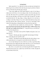
A
sample
geometry
for
this
type
of
machine,
known
as
the
interior
permanent
magnet
(IPM)
synchronous
motor,
is
shown
in
Fig.
1.
Although
this
may
at
first
seem
to
be
a
relatively
modest
variation
of
the
surface
PM
geometry,
the
process
of
covering
each
magnet
with
a
steel
pole
piece
in
the
IPM
geometry
produces
several
significant
effects
on
the
motor's
operating
characteristics.
For
example,
burying
the
magnets
inside
the
rotor
provides
the
basis
for
a
mechanically
robust
rotor
construction
capable
of
high
speeds
since
the
magnets
are
physically
contained
and
protected.
In
electromagnetic
terms
the
introduction
of
steel
pole
pieces
fundamentally
alters
the
machine
magnetic
circuits,
changing
the
motor's
torque
production
characteristics.
The
nature
of
these
changes
and
their
beneficial
consequences
will
be
discussed
at
length
in
the
body
of
this
paper.
The
basic
IPM
rotor
configuration
has
been
known
for
many
years.
The
introduction
of
Alnico
magnets
nearly
50
years
ago
created
a
considerable
interest
in
PM
alternator
development
using
interior
PM
motor
geometries
[4],
[5].
Soft
iron
pole
shoes
in
these
alternators
provided
a
means
of
concentrating
the
flux
of
the
thick
Alnico
magnets.
Improve-
ments
in
PM
materials
in
following
years
turned
attention
to
integral-horsepower
applications
for
PM
synchronous
motors.
A
combination
of
an
induction
motor
squirrel
cage
and
the
interior
PM
geometry
provided
possibilities
for
efficient
steady-state
operation
as
well
as
robust
line
starting
[6].
Work
in
this
area
accelerated
during
the
past
decade,
following
dramatic
increases
in
the
cost
of
energy
[7].
Reports
of
variable-speed
applications
of
interior
PM
synchronous
motors
also
began
to
appear
during
the
past
decade.
Most
of
this
published
work
has
originated
in
Europe,
with
Lajoie-Mazenc
and
his
colleagues
in
France
among
the
most
active
investigators
[8],
[9].
The
IPM
synchronous
motor
has
also
been
explored
in
Europe
for
electric
vehicle
traction
applications
[10].
B.
Scope
of
the
Present
Work
The
purpose
of
this
paper
is
to
investigate
the
potential
for
achieving
high-performance
adjustable-speed
operation
by
0093-9994/86/0700-0738$01.00
©
1986
IEEE
738
JAHNS
et
al.:
INTERIOR
PERMANENT-MAGNET
SYNCHRONOUS
MOTORS
Non-magnetic
Spacers
Fig.
1.
Typical
IPM
synchronous
motor
lamination
configuration.
combining
an
IPM
synchronous
motor
with
a
transistorized
inverter.
Rather
than
describe
a
particular
drive
system,
the
objective
of
this
paper
is
to
identify
and
discuss
more
broadly
the
distinguishing
features
of
the
IPM
synchronous
motor
for
adjustable-speed
operation.
In
the
process
the
paper
will
draw
on
the
collective
experience
of
the
authors
with
various
motor
designs
and
prototype
drive
systems
tested
to
date.
Despite
a
desire
to
be
as
general
as
possible,
the
scope
of
the
paper
will
be
limited
in
at
least
two
ways.
First,
the
discussion
will
address
IPM
synchronous
motors
with
radially
oriented
magnets
based
on
the
sample
configuration
in
Fig.
1.
Alternative
buried-magnet
motor
designs,
in
which
the
mag-
nets
are
mounted
in
the
interpolar
regions
with
circumferential
magnetization
[11],
[12],
share
many
generic
characteristics
but
will
not
be
specifically
addressed
in
this
paper.
Second,
the
discussion
will
be
limited
to
IPM
synchronous
motor
drive
systems
supplied
from
voltage
sources
with
regulation
of
the
instantaneous
motor
phase
currents,
appropriate
for
high-
performance
applications.
The
implications
of
IPM
synchro-
nous
motor
operation
with
a
classic
current
source
inverter
(i.e.,
ASCI-type)
will
be
discussed
only
indirectly.
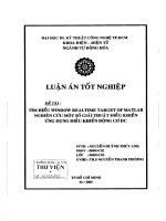
A
sketch
of
a
typical
IPM
synchronous
motor
drive
power
stage
is
provided
in
Fig.
2,
consisting
of
a
six-switch
full
bridge
inverter
which
develops
adjustable-frequency
three-
phase
excitation
from
a
dc
voltage
source
(e.g.,
a
line
rectifier
output
or
battery
bank).
The
switches
are
illustrated
as
bipolar
transistors,
but
any
other
bipolar-
or
MOS-based
power
switch
device,
which
can
be
turned
off
as
well
as
on
from
low-level
gating
commands,
can
also
fill
this
role.
Each
switch
is
combined
with
a
parallel
freewheeling
rectifier
to
provide
circulation
paths
for
the
motor
reactive
phase
currents.
As
shown
in
Fig.
2,
it
is
assumed
that
the
drive
control
electronics
is
provided
with
sensor
feedback
information
from
the
three
stator
phase
currents
and
the
rotor
position.
II.
MOTOR
ELECTROMAGNETIC
CHARACTERISTICS
A.
IPM
Rotor
Magnetic
Circuit
Saliency
In
order
to
understand
the
operating
characteristics
of
an
IPM
synchronous
motor
drive,
it
is
necessary
first
to
appreciate
the
distinguishing
electromagnetic
properties
of
the
interior
PM
motor
itself.
In
particular,
it
is
important
to
recognize
that
burying
the
magnets
inside
the
rotor
introduces
saliency
into
the
rotor
magnetic
circuit
which
is
not
present
in
other
types
of
PM
machines.
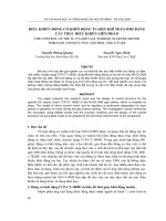
By
using
the
sample
four-pole
rotor
geometry
shown
in
Fig.
1,
the
magnetic
flux
induced
by
the
magnets
defines
a
direct
or
d
axis
radially
through
the
centerline
of
the
magnets;
see
Fig.
3(a).
In
the
process
an
orthogonal
quadrature
or
q
axis
is
defined
through
the
interpolar
region
separated
from
the
d
axis
by
45
mechanical
degrees
(i.e.,
90
electrical
degrees
for
a
four-pole
design)
as
shown
in
Fig.
3(b).
As
sketched
in
Fig.
3(a)
and
(b),
the
magnetic
flux
passing
through
the
d-axis
magnetic
circuit
must
cross
two
magnet
thicknesses
in
addition
to
two
air-gap
crossings
required
in
both
the
d
and
q
axes.
Since
the
incremental
permeability
of
ceramic
and
rare-earth
magnet
materials
is
nearly
that
of
free
space,
the
magnet
thicknesses
appear
as
large
series
air
gaps
in
the
d-axis
magnetic
flux
paths.
Since
the
q-axis
magnetic
flux
in
Fig.
3(b)
can
pass
through
the
steel
pole
pieces
without
crossing
the
magnet
air
gaps,
the
stator
phase
inductance
is
noticeably
higher
with
q-axis
rotor
orientation.
The
elevated
permeance
of
the
rotor
q-axis
magnetic
circuit
can
be
employed
to
enhance
the
adjustable-
speed
operating
characteristics
of
IPM
synchronous
motors.
For
example,
the
additional
inductance
can
be
useful
for
depressing
the
required
inverter
switching
frequency
with
the
IPM
synchronous
motor
compared
to
other
types
of
ac
machines,
as
demonstrated
in
Fig.
4.
The
relative
magnitudes
of
the
d-
and
q-axis
inductance
values
depend
on
the
details
of
the
rotor
geometry,
and
measured
inductance
ratios
of
three
or
higher
have
been
reported
in
the
literature
[13].
The
torque
production
in
the
IPM
motor
is
altered
as
a
result
of
the
rotor
saliency,
providing
design
flexibility
which
can
be
exercised
to
shape
the
motor
output
characteristics
benefi-
cially.
Note
that
the
q-axis
inductance
of
the
IPM
synchronous
motor
(Lq)
typically
exceeds
the
d-axis
inductance
(Ld),
a
feature
which
distinguishes
the
IPM
motor
from
conventional
wound-rotor
salient-pole
synchronous
motors
for
which
Ld
>
Lq.
This
reversal
in
the
relative
inductance
values
for
the
two
axes
has
a
direct
effect
on
the
torque
production
and
excitation
requirements
for
the
IPM
motor
which
will
be
discussed
in
the
following
sections.
B.
Motor
Equivalent
Circuit
and
Torque
Production
The
magnetic
saliency
of
the
IPM
synchronous
motor
rotor
dictates
that
the
electrical
equivalent
circuit
be
developed
in
the
rotor
reference
frame.
Standard
assumptions
regarding
the
sinusoidal
stator
winding
distribution
and
the
absence
of
iron
saturation
are
made
in
order
to
carry
out
this
develop-
ment.
By
adopting
the
same
orthogonal
d
and
q
axes
defined
in
the
preceding
section,
Park's
transformation
yields
the
classic
two-axis
equivalent
circuit
for
a
salient-pole
synchronous
motor
[14]
shown
in
Fig.
5.
This
is
the
same
basic
coupled-
circuit
pair
used
to
model
conventional
wound-rotor
salient-
pole
synchronous
motors.
Although
the
derivation
of
this
model
is
not
included
here,
the
significance
of
some
of
the
important
equivalent
circuit
elements
deserves
discussion.
The
rotor
field
excitation
739
IEEE
TRANSACTIONS
ON
INDUSTRY
APPLICATIONS,
VOL.
IA-22,
NO.
4,
JULY/AUGUST
1986
SHAFT
ANGLE
TRANSDUCER
Fig.
2.
Simplified
schematic
of
IPM
synchronous
motor
drive.
d
Axis
(a)
(b)
Fig.
3.
Principal
IPM
magnetic
flux
paths.
(a)
d
axis.
(b)
q
axis.
Rqr
Fig.
4.
Simulation
results
comparing
IPM
and
induction
motor
phase
current
for
equally
rated
3-hp
motors
under
identical
load
and
supply
test
conditions
with
hysteresis-band
current
regulation.
xds
(Ld
+
Lmd
)
id
+
Lmd
idr
+
Lmd
If
qs=
(L
tq
+Lmq
)
q
+Lmq
1qr
Fig.
5.
IPM
synchronous
motor
equivalent
circuit
in
rotor
reference
frame.
DC
SOURCE
740
JAHNS
et
al.:
INTERIOR
PERMANENT-MAGNET
SYNCHRONOUS
MOTORS
produced
by
the
permanent
magnets
is
modeled
by
an
equivalent
constant
current
source
If,
providing
magnetizing
flux
"mag
=
LmdIf
in
the
d
axis.
The
higher
permeance
of
the
q-axis
magnetic
circuit
is
reflected
in
the
distinct
inductance
elements
in
the
two
axis
circuits
such
that
Lq(
=
Llq
+
Lmq)
is
larger
than
Ld(
=
Lld
+
Lmd).
For
completeness,
the
damper
winding
elements
Ldr,
Rdr
and
Lqr,
Rqr
are
included
in
each
of
the
axis
circuits.
These
elements
can
be
used
to
model
discrete
damper
circuits
purposely
included
in
the
rotor
design
[15]
as
well
as
distributed
rotor
eddy-current
effects
when
deemed
appropriate.
For
steady-state
operation
when
the
damper
transients
have
decayed
to
negligible
levels,
the
average
torque
Te
developed
by
the
IPM
synchronous
motor
can
be
expressed
in
terms
of
the
Fig.
5
equivalent
circuit
d-q
currents
as
Te
=
15P[Iqslmag
+
(Ld-Lq)IqsIdsl
(1)
where
*fmag
permanent
magnet
flux
linkage
(=LmdIf),
Ld,
Lq
total
d
axis
(=
Lmd
+
Lid)
and
q-axis
(LLmq
+
Llq)
stator
inductances,
p
number
of
pole
pairs,
Iqsj
Ids
steady-state
q-axis
and
d-axis
stator
currents.
Each
of
the
two
terms
in
this
equation
reflects
an
important
aspect
of
the
torque
production
in
an
IPM
synchronous
motor.
First,
the
magnet
flux
oriented
along
the
rotor
d
axis
interacts
with
the
q-axis
stator
current
to
produce
a
field-alignment
torque
proportional
to
the
('I'mag
Iqs)
product.
This
is
the
same
process
by
which
torque
is
produced
in
a
conventional
surface
PM
synchronous
motor.
In
addition,
the
current-induced
magnetic
fluxes
along
the
two
axes
LdIds
and
LqIqs
interact
with
the
orthogonal
current
components
to
contribute
a
second
torque
term.
The
rotor
saliency
is
clearly
responsible
for
the
presence
of
this
reluctance
torque
term,
which
is
proportional
to
the
axis
inductance
difference
(Ld
-
Lq).
Thus
the
torque
equation
suggests
that,
for
purposes
of
conceptualization,
the
IPM
motor
can
be
interpreted
as
a
hybrid
combination
of
the
conventional
synchronous-reluctance
and
surface
PM
ma-
chines.
The
IPM
drive
system
performance
characteristics
can
be
influenced
by
adjusting
the
IPM
rotor
design
parameters
to
control
the
relative
contributions
of
the
field-alignment
and
reluctance
torque
tertns.
For
example,
overexcitation
condi-
tions
in
a
PM
synchronous
motor
drive
pose
potential
dangers
to
the
drive
electronics
when
the
magnet-generated
motor
back
EMF
significantly
exceeds
the
source
voltage
at
high
speeds.
The
rotor
saliency
can
be
employed
to
reduce
the
PM
excitation
flux
requirements
in
the
IPM
motor
in
order
to
achieve
extended-speed
operating
ranges
while
proportionally
reducing
the
overexcitation
amplitude
and
its
attendant
risks.
From
an
economic
standpoint,
rotor
saliency
provides
oppor-
tunities
for
reducing
the
volume
of
magnet
material
in
the
IPM
motor
which
would
othetwise
be
required
to
achieve
a
desired
motor
power
rating.
C.
Effect
of
Iron
Saturation
The
nonlinear
performance
effects
introduced
by
iron
saturation
in
any
ac
machine
are
further
complicated
in
the
IPM
synchronous
motor
by
the
salient
rotor
magnetic
circuits.
When
the
MMF
contributions
of
the
rotor
magnets
and
the
d-
and
q-axis
stator
current
components
are
summed,
the
resulting
unsaturated
air-gap
flux
distribution
shown
in
Fig.
6
has
a
distinctly
nonsinusoidal
waveshape
[16].
The
elevated
magnetic
permeance
of
the
rotor
q
axis
provides
conditions
for
high
magnetic
flux
densities
at
the
edges
of
the
iron
pole
pieces.
As
a
result,
the
stator
teeth
opposite
the
leading
edges
of
these
poles
are
particularly
vulnerable
to
iron
saturation
as
the
current
excitation
level
is
raised.
The
saturation
of
these
segments
of
the
stator
teeth
has
the
effect
of
reducing
the
fundamental
spatial
component
of
the
air-gap
flux
density
for
a
given
stator
current
and
shifting
it
toward
the
center
of
the
pole.
From
the
terminals
of
the
motor
this
air-gap
flux
reduction
appears
as
a
reduction
in
the
stator
inductances,
particularly
in
the
higher
permeance
q-axis
circuit.
The
inherent
nonlinear
nature
of
these
saturation
effects,
combined
with
the
salient
rotor
structure,
creates
cross-coupling
effects
in
the
two
flux
axes,
which
pose
difficult
modeling
problems
beyond
the
scope
of
this
paper
[16],
[17].
However,
it
is
clear
that
iron
saturation
typically
serves
to
linearize
the
torque
versus
stator
current
relationship
at
higher
currents,
compared
to
the
ideal
case
without
saturation
as
shown
in
Fig.
7.
D.
Motor
Losses
and
Efficiency
An
attractive
performance
characteristic
which
the
IPM
synchronous
motor
shares
with
other
types
of
permanent
magnet
ac
motors
is
its
high
electrical
efficiency.
The
rotor
losses
in
the
IPM
motor
are
significantly
lower
than
in
a
comparable
induction
motor,
since
no
current-carrying
wind-
ings
exist
on
the
rotor
to
accumulate
resistive
I2R
losses.
The
reductions
in
the
rotor
losses
are
particularly
valuable
since
losses
are
almost
always
more
difficult
to
thermally
extract
from
a
spinning
rotor
than
from
the
surrounding
stator.
Tests
with
prototype
IPM
synchronous
motors
have
con-
firmed
their
very
attractive
power
density
and
loss
characteris-
tics
compared
to
other
types
of
ac
machines.
For
example,
a
3-
hp
prototype
IPM
synchronous
motor
tested
at
its
rated
speed
of
4800
r/min
has
demonstrated
a
full-load
efficiency
in
excess
of
94
percent.
Since
ferrite
magnets
are
used
in
this
particular
machine,
confidence
exists
that
such
efficiency
numbers
will
be
pushed
still
higher
in
future
motors
designed
with
new
generations
of
high-energy-product
neodymium-iron
magnets
[3].
III.
IPM
ADJUSTABLE-FREQUENCY
EXCITATION
ISSUES
A.
Basis
of
Instantaneous
Torque
Control
A
prerequisite
for
high-performance
velocity
or
position
control
in
all
adjustable-speed
ac
drives
is
responsive
control
of
the
instantaneous
torque.
In
particular,
it
is
vital
to
minimize
the
sources
of
pulsating
torque
in
order
to
prevent
undesired
pulsations
in
the
rotor
speed.
This
requirement
has
a
significant
effect
on
the
techniques
for
achieving
instantaneous
torque
control
in
an
IPM
synchronous
motor.
The
torque
production
in
any
ac
motor
can
be
interpreted
as
resulting
from
the
interaction
of
the
air-gap
magnetic
flux
density
distribution
and
the
stator
current
MMF
distribution
741
IEEE
TRANSACTIONS
ON
INDUSTRY
APPLICATIONS,
VOL.
IA-22,
NO.
4,
JULY/AUGUST
1986
d
q
Axis
Axis
0
Fig.
6.
Nominal
IPM
air-gap
magnetic
flux
density
distribution.
Saturation
Effect
8
O
Equivalent
CirGuit
I'
6
>
Prediction
asured
Data
e
L
4.
F
t
2
I8b
5
1
15
28
25
38
35
Line
Curent
-
Amps
xM
Fig.
7.
Comparison
of
linear
equivalent
circuit
model
steady-state
torque
prediction
with
measured
test
results
for
3-hp
prototype
IPM
drive.
along
the
stator
air-gap
surface.
As
shown
in
Fig.
6,
the
air-gap
flux
density
distribution
in
the
IPM
motor
is
distinctly
nonsinusoidal.
Under
these
conditions
the
most
convenient
way
of
producing
a
smooth
constant
torque
is
to
generate
a
synchronously
rotating
stator
current
MMF
wave
which
is
fixed
in
space
relative
to
the
rotor
surface.
This
requirement
for
a
uniform
traveling
MMF
wave
strongly
suggests
balanced
sinusoidal
excitation
of
the
three-phase
stator
windings
which,
by
assumption,
are
sinusoidally
distributed.
Conversely,
square
wave
excitation
will
not
meet
the
conditions
for
smooth
torque
generation
in
the
IPM
motor,
since
the
square
waves
will
produce
an
MMF
wave
which
discretely
shifts
along
the
air
gap
only
at
the
switching
instants.
This
unacceptability
of
square
wave
excitation
distinguishes
the
IPM
synchronous
motor
from
its
surface-
magnet
counterpart
which
can
be
designed
for
sinusoidal
or
square-wave
excitation
[18].
The
control
of
the
instantaneous
phase
currents
provides
a
direct
means
of
controlling
the
instantaneous
torque
developed
by
the
motor.
This
becomes
particularly
apparent
when
the
motor
is
designed
to
minimize
all
rotor
damper
effects
(see
Fig.
2),
because
without
dampers
the
torque
equation
(1)
applies
for
instantaneous
values
of
the
torque
and
current
as
well
as
for
the
average
values.
That
is,
the
removal
of
the
damper
effects
causes
the
torque
to
respond
immediately
to
changes
in
the
stator
current
components
id
and
iq
without
dynamic
terms
associated
with
the
damper
transients.
Since
the
absence
of
these
dynamics
permits
valuable
simplifications
of
the
torque
control
algorithm
described
in
the
following
sections,
it
will
be
assumed
that
rotor
damper
effects
are
negligible
for
the
remainder
of
this
paper.
Several
pulsewidth
modulation
(PWM)
techniques
have
been
developed
to
provide
control
of
the
instantaneous
phase
currents
for
any
polyphase
ac
machine
[19],
[20].
Although
these
algorithms
will
not
be
described
here,
it
must
be
noted
that
sinusoidal
control
of
the
three-phase
currents
typically
requires
current
sensors
in
series
with
the
individual
phase
windings.
In
addition,
the
sinusoidal
excitation
of
the
IPM
synchronous
motor
requires
rotor
angle
feedback
with
suffic-
ient
resolution
to
synchronize
the
sinusoidal
references
prop-
erly
with
the
rotor
position.
These
requirements
are
generally
more
demanding
than
for
comparable
six-step
square-wave
current
excitation
configurations
for
which
the
rotor
angle
information
is
necessary
only
in
600
increments.
B.
Stator
Current
Vector
Control
The
relationships
between
the
stator
phase
current
ampli-
tudes
and
the
instantaneous
torque
can
be
conveniently
described
with
the
aid
of
vector
notation.
Fig.
8(a)
shows
the
three
stator
phase
axes
defined
at
1200
intervals,
with
two
motor
poles
assumed
for
simplicity.
If
each
scalar
phase
current
is
depicted
as
a
magnitude-scaled
vector
along
its
appropriate
axis
(or
negative
axis
for
negative
current
values),
the
three
component
phase
current
vectors
can
be
vectorially
summed
to
form
the
resultant
stator
current
vector
is
shown
in
Fig.
8(a).
Note
that
all
of
the
currents
are
instantaneous
values.
For
steady-state
balanced
excitation,
vector
is
will
have
a
constant
amplitude
and
rotate
at
the
excitation
angular
frequency
We.
Fig.
8(b)
shows
how
this
stator
current
vector
is
can
be
usefully
related
to
the
rotor.
The
instantaneoujs
position
of
the
rotor
d
axis
defined
by
the
rotor
magnet
flux
(see
Fig.
3)
is
at
an
angle
Or
with
respect
to
the
phase
A
stator
axis.
At
every
instant
the
stator
current
vector
can
be
decomposed
into
its
two
orthogonal
components
id
and
iq
along
the
rotor
d
and
q
axes
as
shown
in
Fig.
8(b).
For
a
fixed
stator
current
magnitude,
id
and
i,
become
constant
values
when
the
angular
velocity
of
the
current
vector
is
forced
to
match
that
of
the
rotor.
This
synchronization
of
excitation
and
rotor
speeds
satisfies
a
necessary
condition
for
smooth
instantaneous
torque
produc-
tion
in
a
synchronous
machine.
Fig.
9
shifts
the
viewpoint
from
the
stator
reference
frame
depicted
in
Fig.
8
to
the
rotor
reference
frame
fixed
to
the
rotor
d
and
q
axes.
Assuming
that
the
damper
effects
are
made
negligible
by
design,
the
relationship
betweeni
the
instantane-
ous
stator
current
components
(id
and
iq)
and
the
torque
Te
is
expressed
by
(1).
Within
the
limits
of
iron
saturation,
this
equation
defines
a
hyperbola
of
(id,
iq)
couples
in
the
rotor
reference
frame
for
every
value
of
torque.
Fig.
9
shows
the
resulting
curve
for
one
particular
value
of
positive
torque
along
with
three
of
the
infinite
number
of
stator
current
vectors
which
would
deliver
this
same
torque.
A
closer
examination
of
(1)
reveals
that
useful
insights
can
be
gained
from
normalization
as
follows:
Ten
=
iqn(l-idn)
(2)
742
JAHNS
et
al.:
INTERIOR
PERMANENT-MAGNET
SYNCHRONOUS
MOTORS
B
Axis
A
Axis
A
ic
iA
+
i
B
+
ic
=
°
Axi
s
(a)
(b)
Fig.
8.
Instantaneous
current
vector
definition.
(a)
In
terms
of
stator
phase
currents.
(b)
In
rotor
reference
frame,
including
id
-
iq
decomposition.
q
Axis
/
/
d
Axis
Fig.
9.
Typical
constant
torque
locus
for
IPM
synchronous
motor
in
rotor
reference
frame
showing
three
sample
stator
current
vectors
delivering
same
electromagnetic
torque.
where
I'l
-
3.
*=¾.=
-3.0
2
0
Fig.
10.
Constant
torque
loci
for
IPM
synchronous
motor
in
terms
of
normalized
phase
current
and
torque
variables.
Current
vector
trajectory
for
maximum
torque/ampere
is
also
plotted.
several
different
values
of
normalized
torque.
Normalization
allows
these
curves
to
apply
to
any
combination
of
IPM
motor
parameter
values
within
the
linearity
limits
imposed
by
iron
saturation,
etc.
In
addition
to
the
symmetry,
note
that
Ten
is
positive
throughout
the
second
quadrant
(motoring
torque
for
counterclockwise
(CCW)
rotation)
and
negative
in
the
third
quadrant
(braking
torque
for
CCW
rotation).
Since
a
particular
value
of
torque
can
be
developed
with
an
infinite
set
of
distinct
(idn,
iqn)
combinations,
a
question
naturally
arises
regarding
the
optimal
choice
of
idn
and
iqn
as
Ten
varies.
If
motor
efficiency
is
an
important
performance
characteristic,
one
attractive
optimization
criteria
is
maximum
torque
per
stator
current
ampere.
Fig.
10
includes
the
idn,
iqn
trajectory
of
maximum
torque/ampere
for
positive
and
nega-
tive
torque
values.
Note
that
each
trajectory-torque
curve
intersection
represents
the
point
on
that
particular
curve
which
is
closest
to
the
origin,
corresponding
to
a
minimum
stator
current.
Fig.
11
provides
plots
of
the
idn
and
iqn
coordinates
for
the
maximum
torque/ampere
trajectory
as
a
function
of
the
normalized
torque.
These
trajectories
are
defined
(using
primed
variables)
by
the
following
equations:
Ten
=AiTn
(
~idn
1
j
(3)
Id
Idn
=
ib
en
[1+
l+4(iqn)2]
*b=
mag
(Lq-Ld)
Teb=
1P5Pmagib-
All
of
the
motor
parameters
are
eliminated
from
the
resulting
normalized
torque-current
relationship.
Fig.
10
provides
a
family
of
curves
in
the
normalized
iqn,
idn
plane
for
Some
interesting
insights
into
the
IPM
synchronous
motor
torque
production
are
found
by
examining
the
details
of
this
maximum
torque/ampere
trajectory.
First,
note
that
the
trajectory
in
Fig.
10
is
tangent
to
the
q
axis
at
the
origin
and
asymptotes
to
450
trajectories
in
both
the
second
and
third
quadrants.
This
clearly
reflects
the
hybrid
nature
of
torque
production
in
the
IPM
motor,
since
the
q
axis
represents
the-
Te
Ten
=-
Teb
Iq
iqn
=
.
ib
743
(4)
IEEE
TRANSACTIONS
ON
INDUSTRY
APPLICATIONS,
VOL.
IA-22,
NO.
4,
JULY/AUGUST
1986
t
2.0
01
1.5
q
.~0.5
-t
IZS
_
ldn
-t.5_
_2.0.
Normalized
Torque,
Ten
+
Fig.
11.
Calculated
normalized
stator
current
components
as
function
of
normalized
torque
for
maximum
torque/ampere
trajectory.
Iron
saturation
effects
neglected.
optimal
trajectory
for
the
field-alignment
torque
alone
while
the
450
asymptotes
correspond
to
the
reluctance
torque
term
(Lq
>
Ld).
As
the
torque
is
increased,
the
reluctance
torque
term,
proportional
to
the
square
of
the
current,
increasingly
dominates
the
field-alignment
torque
term,
which
is
only
linearly
proportional
to
current.
This
hybrid
quality
is
also
reflected
in
(4)
where
Te'
i',
for
low
current
values
and
Ten
(i
')2
for
high
currents.
Although
the
preceding
discussion
is
idealized
since
it
strictly
applies
only
for
constant
motor
parameters,
further
study
has
indicated
that
all
of
the
key
observations
hold
in
the
presence
of
moderate
iron
saturation.
As
a
result
of
the
localized
stator
teeth
saturation
associated
with
the
Fig.
6
flux
distribution,
the
maximum
torque/ampere
trajectory
tends
to
shift
toward
the
q
axis
as
the
stator
current
is
increased.
In
addition,
the
iron
saturation
tends
to
linearize
the
torque-
current
relationship
at
high
currents
as
shown
in
Fig.
7.
C.
Feedforward
Torque
Control
Configuration
At
this
point
all
of
the
key
concepts
necessary
to
design
a
high-performance
torque
controller
for
the
IPM
synchronous
motor
have
been
introduced.
Although
a
wide
range
of
alternative
designs
might
be
proposed,
a
simple
feedforward
torque
controller
configuration
will
be
discussed
for
illustra-
tion
purposes.
Besides
simplicity,
the
feedforward
controller
shown
in
Fig.
12
has
the
advantage
of
requiring
only
phase
current
and
rotor
position
feedback.
However,
the
feed-
forward
nature
of
the
controller
demands
that
the
motor
characteristics
be
directly
reflected
in
the
function
blocks
f,(Te*)
and
f2(Te*).
(The
asterisks
denote
the
commanded
values.)
As
discussed
in
preceding
sections,
minimizing
the
rotor
damper
effects
results
in
the
elimination
of
the
dynamic
terms
from
the
stator
current-torque
relationship.
Thus
the
function
blocks
f,
and
f2,
which
convert
the
incoming
torque
requests
into
the
required
stator
current
component
commands
id
and
i
,
can
be
simple
time-independent
function
generators.
Although
an
infinite
number
of
candidates
exist
for
fi
and
f2,
the
curves
in
Fig.
11
provide
attractive
choices
if
high
motor
efficiency
with
maximum
torque/ampere
is
important.
The
vector
rotator
stage
converts
the
i
d
and
i
*
commands
d
q
into
equivalent
phase
current
commands
i*
i*
*
and
iC*
A'
B'
C
requiring
a
coordinate
transformation
from
the
rotor
reference
frame
to
the
stator
frame.
This
operation
requires
information
on
the
instantaneous
rotor
position
0r
to
ensure
proper
synchronization
at
all
times.
By
using
rotor
position
sensor
feedback
to
perform
this
synchronization,
no
danger
exists
of
pole
slippage
between
the
excitation
and
rotor
position
regardless
of
loading
conditions.
The
defining
trigonometric
relations
are
given
by
iA
=
id
cos
(Or)-
i
sin
(0,)
i*
=
id
cos
(fOr-120
)-
i
sin
(0r,-
120
)
ic=id
cos
(Or+
120')-i
*
sin
(0,+
1200).
(5)
(6)
(7)
These
instantaneous
phase
current
commands
are
then
ampli-
fied
and
applied
to
the
motor
phase
windings
by
means
of
the
power
converter
stage,
using
phase
current
feedback
to
provide
PWM
closed-loop
current
regulation.
The
dynamic
response
characteristics
of
the
IPM
synchro-
nous
motor
drive
with
this
type
of
feedforward
torque
control
scheme
are
compatible
with
the
requirements
of
many
high-
performance
applications.
The
digital
simulation
results
pre-
sented
in
Fig.
13
illustrate
a
typical
IPM
drive
system
response
to
a
large-signal
step
in
the
torque
request.
The
motor
parameters
for
this
simulation
have
been
drawn
from
a
prototype
5-hp
2200
r/min
prototype
IPM
synchronous
motor.
Fig.
13
indicates
that
the
rise
time
for
the
instantaneous
torque
is
less
than
I
ms
for
these
typical
conditions.
The
residual
high-frequency
pulsations
in
the
currents
and
torque
are
associated
with
the
PWM
switching
which
executes
the
current
regulation.
Note
that
the
d-axis
stator
current
id
responds
more
rapidly
than
the
q-axis
current
iq,
which
is
consistent
with
the
lower
d-axis
inductance
value.
Although
rotor
dampers
might
be
introduced
to
accelerate
these
re-
sponses,
the
adverse
damper
effects
on
the
inverter
switching
frequency
and
losses
demand
special
trade-off
considerations
which
will
not
be
discussed
here.
All
of
the
important
variable
responses
in
Fig.
13
are
well-behaved,
as
confirmed
by
laboratory
tests.
D.
Six-Step
Saturated
Regulator
Operation
The
finite
dc
bus
voltage
is
responsible
for
imposing
limits
on
the
drive
system
torque-speed
operating
envelope
at
high
speeds.
The
nature
of
this
limit
can
be
understood
by
noting
that
for
any
given
values
of
the
stator
current
components
id
and
iq
(and
thus
torque),
the
stator
voltage
vector
amplitude
is
nearly
proportional
to
speed.
When
the
resulting
line-to-line
terminal
voltage
approaches
the
fixed
dc
bus
voltage
as
the
speed
is
increased,
the
driving
voltage
necessary
to
force
the
stator
currents
to
their
commanded
values
decays
to
zero.
Under
these
conditions
the
current
regulators
saturate,
the
pulses
in
the
phase
voltage
waveforms
drop
out
as
the
PWM
current
control
is
lost,
and
the
system
eventually
reverts
to
six-
step
voltage
excitation.
Fig.
14
presents
some
typical
IPM
motor
phase
voltage
and
current
waveforms
measured
during
the
six-step
voltage
744
JAHNS
et
at.:
INTERIOR
PERMANENT-MAGNET
SYNCHRONOUS
MOTORS
745
PHASE
CURRENT
FEEDBACK
SHAFT
ANGLE
TRANSDUCER
Fig.
12.
Feedforward
torque
control
block
diagram
for
IPM
synchronous
motor
drive.
Time,
t
[s]
i
(a)
12.
q
4.
0.
.
id
-4._
-8.
000.
0
'.
0:01
0.0
O
.'03
0.0d
Time,
t
[s]
(b)
12.'
"10.
F<U18
.
4.
Er6.
S-
0.
0.01
0.02
0.03
0.04
Time,
t
[SI
-
(c)
Fig.
13.
Transient
response
simulation
of
IPM
drive
using
feedforward
torque
controller
to
large-signal
torque
command
step.
Parameters
from
5-
hp
prototype
drive
operating
at
1000
r/min,
V,
325-V
dc,
fPwM
3
kHz.
Fig.
14.
Measured
six-step
excitation
phase
current
and
phase
voltage
waveforms
for
3-hp
prototype
IPM
drive
at
4100
r/min.
Upper:
iA
-
10
A/div.
Lower:
VA,
-
50
V/div.
Horizontal:
t
-
2
ms/div.
excitation
of
a
3-hp
prototype
drive
system.
Although
the
phase
currents
are
no
longer
regulated
to
follow
the
sinusoidal
references,
the
elevated
phase
inductances
of
the
IPM
motor
serve
the
useful
purpose
of
filtering
the
six-step
voltage
harmonic
components,
thereby
limiting
the
periodic
current
peaks.
These
current
peaks
are
undesirable
because
of
the
their
adverse
effects
on
the
peak
current
ratings
of
the
inverter
switches,
inverter
switching
losses,
and
pulsating
torque
components.
The
saturation
of
the
current
regulators
with
the
onset
of
six-step
voltage
excitation
requires
the
nature
of
the
IPM
drive
torque
control
to
change
from
current
control
to
voltage
control.
This
transition
typically
entails
some
degradation
in
the
torque
control
characteristics,
since
only
the
voltage
vector
angle
and
not
the
amplitude
can
be
adjusted
during
six-step
excitation.
The
availability
of
rotor
position
feedback
at
all
speeds
makes
it
possible
to
control
this
voltage
vector
flexibly
angle
during
six-step
operation
without
any
danger
of
pole
slippage
(pullout),
just
as
during
regulated-current
operation.
Although
this
voltage
control
mode
will
not
be
discussed
in
detail
in
this
paper,
note
that
six-step
voltage
excitation
can
significantly
expand
the
achievable
torque-speed
operating
envelope
of
the
IPM
drive.
Considerable
ranges
of
constant-
.
E
0
U
4,
c
3
IEEE
TRANSACTIONS
ON
INDUSTRY
APPLICATIONS,
VOL.
IA-22,
NO.
4.
JULY/AUGUST
1986
horsepower
output
characteristics
can
be
developed
in
the
process.
Such
features
make
the
IPM
synchronous
motor
an
attractive
alternative
for
many
ac
drive
applications
presently
served
by
squirrel-cage
induction
motors.
IV.
CONCLUSION
As
described
in
this
paper,
burying
the
magnets
inside
the
rotor
of
the
IPM
synchronous
motor
has
several
important
effects
on
the
machine's
electromagnetic
characteristics-
some
rather
obvious
and
others
more
subtle.
The
key
to
understanding
these
effects
is
recognition
that
covering
each
magnet
with
an
iron
pole
piece
creates
high-permeance
paths
for
the
magnetic
flux
across
these
poles
and
orthogonal
to
the
magnet
flux.
The
effects
of
this
saliency
show
up
directly
in
the
IPM
torque
equation
where,
in
addition
to
the
field-
alignment
term
common
to
the
surface-magnet
synchronous
motor,
a
second
reluctance
torque
term
exists
which
is
dependent
on
the
magnetic
permeance
difference
in
the
two
orthogonal
rotor
axes.
Furthermore,
the
IPM
motor
is
distinguished
from
conventional
wound-rotor
salient
synchro-
nous
machines
by
the
fact
that
the
IPM
stator
phase
inductance
with
direct-axis
(magnet)
alignment
Ld
is
less
than
the
quadrature-axis
inductance
Lq.
The
same
six-switch
full-bridge
inverter
used
to
excite
the
induction
motor
and
surface
PM
synchronous
motor
can
also
be
used
to
achieve
high-performance
adjustable-frequency
operation
with
an
IPM
synchronous
motor.
Key
insights
and
observations
regarding
the
adjustable-frequency
performance
characteristics
of
the
IPM
motor
include
the
following.
1)
The
basis
of
high-performance
instantaneous
torque
control
with
the
IPM
motor
is
control
of
the
angular
orientation
of
the
stator
phase
excitation
with
respect
to
the
rotor
position
at
all
times.
Rotor
position
transducer
feedback
is
the
standard
means
of
providing
this
self-synchronization
function,
ensuring
that
excitation
pole
slippage
(pullout)
will
never
occur.
This
basic
angle
control
of
the
IPM
synchronous
motor
should
be
distinguished
from
the
frequency
control
(i.e.,
slip
frequency)
incorporated
into
familiar
induction
motor
control
algorithms.
2)
In
particular,
closed-loop
regulation
of
the
motor
phase
currents
provides
an
attractive
means
of
achieving
responsive
instantaneous
torque
control
with
the
IPM
synchronous
motor.
By
exciting
the
motor
with
balanced
sinusoidal
current
waveforms
synchronized
with
the
rotor,
torque
pulsations
will
be
eliminated
at
all
speeds
in
spite
of
nonlinearities
in
the
spatial
air-gap
magnetic
flux
distribution.
3)
A
wide
spectrum
of
alternative
algorithms
can
be
developed
for
executing
torque
control
in
the
IPM
motor
by
means
of
phase
current
regulation.
One
particularly
straight-
forward
candidate
has
been
described
which
uses
feedforward
control
to
convert
directly
an
incoming
torque
command
into
rotor-referenced
stator
current
commands
id
and
iq,
according
to
predefined
functions.
Simulation
(Fig.
13)
and
measured
prototype
results
have
confirmed
that
responsive
torque
control
is
achievable
with
the
IPM
synchronous
motor
using
only
rotor
position
and
phase
current
feedback.
The
adoption
of
these
excitation
control
principles
makes
it
possible
to
achieve
high-performance
adjustable-speed
drive
characteristics
with
the
IPM
synchronous
motor.
As
described
in
the
body
of
this
paper,
the
attractive
features
of
the
IPM
drive
include
high
motor
and
inverter
efficiency,
high
motor
power
density,
low
magnet
weight,
fast
dynamic
response,
and
flexible
torque-speed
envelopes,
including
high-speed
constant-horsepower
operation.
These
features
make
the
IPM
drive
an
appealing
candidate
for
a
wide
variety
of
applications,
ranging
from
high-performance
machine
tool
servos
and
robot
actuators
to
high-power
traction
and
spindle
drives
demanding
wide
speed
operation.
ACKNOWLEDGMENT
The
authors
wish
to
acknowledge
the
contributions
of
present
and
former
colleagues
to
the
development
of
IPM
motor
drive
technology
at
General
Electric.
In
particular,
A.
B.
Plunkett
is
credited
for
major
contributions
and
innovations
derived
from
his
initial
investigations
of
IPM
drive
controls.
We
also
acknowledge
E.
Richter
and
T.
J.
E.
Miller
for
their
valuable
contributions
to
the
IPM
motor
electromagnetic
analysis.
Finally,
we
thank
V.
B.
Honsinger
who
provided
inspiration
for
this
work
through
his
early
investigations
of
IPM
configurations.
REFERENCES
[1]
T.
J.
E.
Miller,
T.
W.
Neumann,
and
E.
Richter,
"A
permanent
magnet
excited
high
efficiency
synchronous
motor
with
line-start
capability,"
in
Conf.
Rec.
18th
Ind.
Appl.
Soc.
Annu.
Meeting,
1983,
pp.
455-461.
[2]
P.
Zimmerman,
"Electronically
commutated
dc
feed
drives
for
machine
tools,"
Drives
Contr.
Int.,
vol.
2,
pp.
13-20,
Oct./Nov.
1982.
[3]
T.
W.
Neumann
and
R.
E.
Tompkins,
"Line
start
motors
designed
with
Nd-Fe-B
permanent
magnets,"
in
Proc.
8th
Int.
Workshop
Rare-
Earth
Magnets,
1985,
pp.
77-89.
[41
F.
Strauss,
"Synchronous
machines
with
rotating
permanent-magnet
fields,"
AIEE
Trans.,
vol.
71,
pt.
III,
pp.
887-893,
Oct.
1952.
[5]
D.
J.
Hanrahan
and
D.
S.
Toffolo,
"Permanent
magnet
generators,
Part
I-Theory,"
AIEE
Trans.,
vol.
76,
pt.
III,
pp.
1098-1103,
Dec.
1957.
[6]
M.
A.
Rahman,
"Design
and
analysis
of
large
permanent
magnet
synchronous
motors,"
in
Proc.
8th
Int.
Workshop
Rare-Earth
Magnets,
1985,
pp.
67-75.
[7]
V.
B.
Honsinger,
"Permanent
magnet
machines:
Asynchronous
operation,"
IEEE
Trans.
Power
App.
Syst.,
vol.
PAS-99,
pp.
1503-
1509,
July/Aug.
1980.
[8]
M.
Lajoie-Mazenc
et
al.,
"An
electrical
machine
with
electronic
commutation
using
high
energy
ferrite,"
in
Proc.
Inst.
Elec.
Eng.
Small
Electrical
Machines
Conf.,
1976,
pp.
31-34.
[9]
M.
Lajoie-Mazenc,
C.
Villanueva,
and
J.
Hector,
"Study
and
implementation
of
hysteresis
controlled
inverter
on
a
PM
synchronous
machine,"
IEEE
Trans.
Ind.
Appl.,
vol.
IA-21,
pp.
408-413,
Mar./
Apr.
1985.
[10]
B.
Sneyers,
G.
Maggetto,
and
J.
L.
Van
Eck,
"Inverter
fed
PM
synchronous
motor
for
road
electric
traction,"
in
Proc.
Int.
Conf.
Electrical
Machines,
1982,
pp.
550-553.
[l1]
V.
B.
Honsinger,
"The
fields
and
parameters
of
interior
type
ac
permanent
magnet
machines,"
IEEE
Trans.
Power
App.
Syst.,
vol.
PAS-101,
pp.
867-875,
Apr.
1982.
[121
W.
Volkrodt,
"Machines
of
medium-high
rating
with
a
ferrite-magnet
field,"
Siemens
Rev.,
vol.
43,
pp.
248-254,
1976.
[13]
M.
Lajoie-Mazenc,
P.
Mathieu,
and
B.
Davat,
"Utilisation
des
aimants
permanents
dans
les
machines
a
commutation
electronique,"
Rev.
Gen.
Elec.,
pp.
605-612,
Oct.
1984.
[14]
R.
H.
Park,
"Two-reaction
theory
of
synchronous
machines:
Part
II,"
AIEE
Trans.,
vol.
52,
pp.
352-355,
June
1933.
[15]
A.
Weschta,
"Damper
windings
of
a
PM
synchronous
servomotor,"
in
Proc.
Int.
Conf.
Electrical
Machines,
1982,
pp.
636-640.
[16]
E.
Richter
and
T.
W.
Neumann,
"Saturation
effects
in
salient
pole
synchronous
motors
with
permanent
magnet
excitation,"
in
Proc.
Int.
746
JAHNS
et
aL.:
INTERIOR
PERMANENT-MAGNET
SYNCHRONOUS
MOTORS
Conf.
Electrical
Machines,
1984,
pp.
603-612.
[17]
B.
Sneyers,
D.
W.
Novotny,
and
T.
A.
Lipo,
"Field
weakening
in
buried
permanent
magnet
ac
motor
drives,"
IEEE
Trans.
Ind.
AppL,
vol.
IA-21,
pp.
398-407,
Mar./Apr.
1985.
[18]
T.
M.
Jahns,
"Torque
production
in
PM
synchronous
motor
drives
with
rectangular
current
excitation,"
IEEE
Trans.
Ind.
App!.,
vol.
IA-20,
pp.
803-813,
July/Aug.
1984.
[19]
A.
B.
Plunkett,
"A
current-controlled
PWM
transistor
inverter
drive,"
in
Conf.
Rec.
14th
Ind.
Appl.
Soc.
Annu.
Meeting,
1979,
pp.
785-
792.
[20]
D.
M.
Brod
and
D.
W.
Novotny,
"Current
control
of
VSI-PWM
inverters,"
IEEE
Trans.
Ind.
Appl.,
vol.
IA-21,
pp.
562-570,
May/
June
1985.
Thomas
M.
Jahns
(S'73-M'78)
received
the
S.B.
and
S.M.
degrees
in
1974
and
the
Ph.D.
degree
in
1978
from
the
Massachusetts
Institute
of
Technol-
ogy,
Cambridge,
all
in
electrical
engineering.
Following
a
year's
employment
by
Alexander
Kusko,
Inc.,
Needham
Heights,
MA,
as
a
power
engineering
consultant,
he
joined
Gould
Laborato-
ries,
Rolling
Meadows,
IL,
in
1979.
At
Gould
he
worked
to
develop
new
ac
drive
systems
for
both
land
and
marine
propulsion
applications
as
well
as
leading
development
projects
in
high-performance
ac
drives
for
industrial
applications.
He
joined
General
Electric
Corporate
Research
and
Development,
Schenectady,
NY,
in
1983
where
he
is
pursuing
new
ac
drive
development
activities
as
a
Staff
Member
in
the
Power
Electronics
Controls
Program.
His
recent
technical
efforts
have
been
focused
on
applying
high-performance
PM
servo
drives
to
aircraft
actuator
and
accessory
applications.
Dr.
Jahns
is
serving
as
an
officer
of
the
Industrial
Drives
Committee
and
is
the
recipient
of
four
IEEE
Industry
Applications
Society
prize
paper
awards.
747
Gerald
B.
Kliman
(S'52-M'55-SM'76)
received
the
S.B.,
S.M.,
and
Sc.D.
degrees
at
the
Massachu-
setts
Institute
of
Technology,
Cambridge,
in
1955,
1959,
and
1965,
respectively.
From
1965
to
1971
he
was
Assistant
Professor
of
Electrical
Engineering
at
Rensselaer
Polytechnic
Institute,
Troy,
NY.
Since
1971
he
has
been
with
the
General
Electric
Company.
From
1971
to
1975
he
worked
on
linear
induction
motor
research
and
on
propulsion
drives
at
the
Transportation
Systems
Division,
Erie,
PA.
From
1975
to
1977,
he
was
Principal
Electromagnetic
Engineer
on
the
development
of
the
world's
largest
electromagnetic
pump
at
the
Fast
Breeder
Reactor
Department,
Sunnyvale,
CA.
Since
1977
he
has
been
at
Corporate
Research
and
Development,
Schenectady,
NY,
working
on
linear
induction
and
synchronous
motor
research,
advanced
drive
systems,
electric
propulsion,
advanced
materials
applications,
and
induction
motor
fault
detection
and
harmonic
behavior.
Dr.
Kliman
is
a
member
of
Sigma
Xi,
Tau
Beta
Pi,
and
Eta
Kappa
Nu.
Thomas
W.
Neumann
received
the
B.S.
and
M.S.
degrees
in
electrical
engineering
from
Northeastern
University,
Boston,
MA.
He
joined
General
Electric's
Corporate
Research
and
Development
Center,
Schenectady,
NY,
in
1978.
His
initial
work
at
GE
focused
on
high-speed
high-performance
electrical
machines
for
aero-
space,
military,
transportation,
and
energy
storage
applications.
In
1980
he
began
work
on
the
develop-
ment
of
a
cost-effective
line-start
permanent-magnet
motor
for
constant
frequency
application.
He
was
successful
in
designing,
building,
and
testing
25-hp
cobalt
samarium,
ferrite,
and
neodymium
iron
magnet
motors.
This
effort
was
then
extended
to
interior
magnet
inverter
driven
motors
for
servo,
spindle,
electric
vehicle,
and
industrial
applications.
In
1985
he
joined
GE's
Motor
Business
Group
in
Fort
Wayne,
IN
as
a
Senior
Development
Engineer.
His
current
responsibilities
include
the
optimization
of
induction
motors
and
the
development
of
permanent-magnet
motors
for
consumer,
commercial,
and
industrial
applica-
tions.
He
has
authored
several
papers
on
permanent-magnet
motors.