Đề Olympic quốc tế 2011 - Thực hành môn vật lý
Bạn đang xem bản rút gọn của tài liệu. Xem và tải ngay bản đầy đủ của tài liệu tại đây (433.45 KB, 6 trang )
Experimental Competition: 14 July 2011
Problem 1 Page 1 of 4
1. Electrical Blackbox: Capacitive Displacement Sensor
For a capacitor of capacitance
C
which is a component of a relaxation oscillator whose frequency
of oscillation is
f
, the relationship between
f
and
C
is as follows:
S
f
CC
where is a constant and
S
C
is the stray capacitance of our circuits. The frequency
f
can be
monitored using a digital frequency meter.
The electrical blackbox given in this experiment is a parallel plate capacitor. Each plate consists of
a number of small teeth of the same geometrical shape. The value of
C
can be varied by displacing
the upper plate relative to the lower plate, horizontally. Between the two plates there is a sheet of
dielectric material.
Equipment: a relaxation oscillator, a digital multimeter for measuring frequency of the relaxation
oscillator, a set of capacitors of known capacitances, an electrical blackbox and a
battery.
Caution: Check the voltage of the battery and ask for a new one if the voltage is less than 9 V.
Do not forget to switch on.
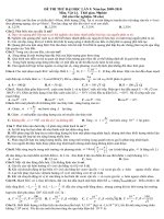
FIGURE 1
Connectors to capacitor
Electrical blackbox:
Parallel plate capacitor
Relaxation oscillator
Sliding upper plate
Battery
Switch
Frequency output
Electrical connectors to
the plates
Experimental Competition: 14 July 2011
Problem 1 Page 2 of 4
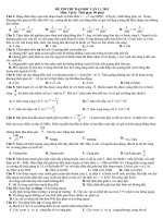
FIGURE 2 Capacitors
FIGURE 3 Digital multimeter for measuring frequency
TABLE 1 Nominal Capacitance values
Code
Capacitance value
(pF)
33J
34 1
68
68 1
82J
84 1
151
150 1
The position for frequency
measurements
Experimental Competition: 14 July 2011
Problem 1 Page 3 of 4
Part 1. Calibration
Perform the measurement of
f
using the given capacitors of known capacitances. Draw appropriate
graph to find the value of and
S
C
. Error analysis is not required. [3.0 points]
Part 2. Determination of geometrical shape of a parallel plate capacitor [6.0 points]
Given the three possible geometrical shapes as Pattern I, Pattern II and Pattern III as follows:
Pattern I
upper plate
lower plate
slide in and out
Pattern II
upper plate
lower plate
slide in and out
Top view
Top view
Experimental Competition: 14 July 2011
Problem 1 Page 4 of 4
For each pattern, draw qualitatively an expected graph of
C
versus the positions of the upper plate
but label the x-axis. Then, perform the measurement of
f
versus the positions of the upper plate.
Plot graphs and, from these graphs, deduce the pattern of the parallel plate capacitor and its
dimensions (values of
andbw
). The separation
d
between the upper and lower plates is 0.20 mm.
The dielectric sheet between the plates has a dielectric constant
1.5K
. The permittivity of free
space
12 -1
0
8.85 10 Fm
. Error analysis is not required.
Part 3. Resolution of digital calipers [1.0 point]
As the relative position of the parallel plates is varied, the capacitance changes with a pattern. This
set-up may be used as digital calipers for measuring length. If the parallel plate capacitor in this
experiment is to be used as digital calipers, estimate from the experimental data in Part 2 its
resolution: the smallest distance that can be measured for the frequency value
5 kHzf
. An error
estimate for the final answer is not required.
Pattern III
upper plate
lower plate
slide in and out
Top view
Experimental Competition: 14 July 2011
Problem 2 Page 1 of 2
2. Mechanical Blackbox: a cylinder with a ball inside
A small massive particle (ball) of mass
m
is fixed at distance
z
below the top of a long hollow
cylinder of mass
M
. A series of holes are drilled perpendicularly to the central axis of the cylinder.
These holes are for pivoting so that the cylinder will hang in a vertical plane.
Students are required to perform necessary nondestructive measurements to determine the numerical
values of the following with their error estimates:
i. position of centre of mass of cylinder with ball inside.
Also provide a schematic drawing of the experimental set-up for measuring the centre of
mass. [1.0 points]
ii. distance
z
[3.5 points]
iii. ratio
M
m
. [3.5 points]
iv. the acceleration due to gravity,
g
. [2.0 points]
Equipment: a cylinder with holes plus a ball inside, a base plate with a thin pin, a pin cap, a ruler, a
stop watch, thread, a pencil and adhesive tape.
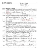
CM
x
is the distance from the top of the cylinder to the
centre of mass.
R
is the distance from the pivoting point to the centre of
mass.
Thin pin
for pivoting
Base plate
to be clamped
to a table top
pivot
M
O
CM
CM
x
L
R
z
m
Experimental Competition: 14 July 2011
Problem 2 Page 2 of 2
Caution: The thin pin is sharp. When it is not in use, it should be protected with a pin cap for safety.
Useful information:
1. For such a physical pendulum,
2
2
2
CM
d
M m R I g M m R
dt
, where
CM
I
is
the moment of inertia of the cylinder with a ball about the centre of mass and is the angular
displacement.
2. For a long hollow cylinder of length
L
and mass
M
, the moment of inertia about the centre of
mass with the rotational axis perpendicular to the cylinder can be approximated by
2
1
32
L
M
.
3. The parallel axis theorem:
2
centre of mass
I I x
M
, where
x
is the distance from the rotation
point to the centre of mass, and
M
is the total mass of the object.
4. The ball can be treated as a point mass and it is located on the central axis of the cylinder.
5. Assume that the cylinder is uniform and the mass of the end-caps is negligible.
Cylinder with holes
plus ball inside
Base plate
Stop
watch
Adhesive
tape
Thread
(for balancing)
Ruler
Pin cap