HƯỚNG DẪN SỬA CHỮA XE NISSAN GTR ĐỜI 2013
Bạn đang xem bản rút gọn của tài liệu. Xem và tải ngay bản đầy đủ của tài liệu tại đây (11.15 MB, 356 trang )
A
B
D
E
F
G
H
I
J
K
L
M
N
P
O
C
QUICK REFERENCE INDEX
A
GENERAL INFORMATION
GI
General Information
B ENGINE
EM
Engine Mechanical
LU
Engine Lubrication System
CO
Engine Cooling System
EC
Engine Control System
FL
Fuel System
EX
Exhaust System
STR
Starting System
ACC
Accelerator Control System
C ELECTRIC POWER TRAIN
HBC
Hybrid Control System
HBB
Hybrid Battery System
HBR
Hybrid Brake System
EVC
EV Control System
TMS
Traction Motor System
EVB
EV Battery System
VC
Vehicle Charging System
HCO
High Voltage Cooling System
D TRANSMISSION & DRIVELINE
CL
Clutch
TM
Transaxle & Transmission
DLN
Driveline
FAX
Front Axle
RAX
Rear Axle
E SUSPENSION
FSU
Front Suspension
RSU
Rear Suspension
SCS
Suspension Control System
WT
Road Wheels & Tires
F BRAKES
BR
Brake System
PB
Parking Brake System
BRC
Brake Control System
G STEERING
ST
Steering System
STC
Steering Control System
H RESTRAINTS
SB
Seat Belt
SBC
Seat Belt Control System
SR
SRS Airbag
SRC
SRS Airbag Control System
I VENTILATION, HEATER & AIR
CONDITIONER
VTL
Ventilation System
HA
Heater & Air Conditioning System
HAC
Heater & Air Conditioning Control System
J BODY INTERIOR
INT
Interior
IP
Instrument Panel
SE
Seat
ADP
Automatic Drive Positioner
K BODY EXTERIOR, DOORS,
ROOF & VEHICLE SECURITY
DLK
Door & Lock
SEC
Security Control System
GW
Glass & Window System
PWC
Power Window Control System
RF
Roof
HD
Hood
EXT
Exterior
BRM
Body Repair
L DRIVER CONTROLS
MIR
Mirrors
EXL
Exterior Lighting System
INL
Interior Lighting System
WW
Wiper & Washer
DEF
Defogger
HRN
Horn
VSP
Approaching Vehicle Sound for Pedestrians (VSP)
M ELECTRICAL & POWER CON-
TROL
PWO
Power Outlet
BCS
Body Control System
LAN
LAN System
PCS
Power Control System
CHG
Charging System
PG
Power Supply, Ground & Circuit Elements
N DRIVER INFORMATION &
MULTIMEDIA
MWI
Meter, Warning Lamp & Indicator
WCS
Warning Chime System
SN
Sonar System
AV
Audio, Visual & Navigation System
O CRUISE CONTROL &
DRIVER ASSISTANCE
CCS
Cruise Control System
DAS
Driver Assistance System
DMS
Drive Mode System
P MAINTENANCE
MA
Maintenance
All Rights Reserved. No part
of this Service Manual may
be reproduced or stored in a
retrieval system, or transmit-
ted in any form, or by any
means, electronic, mechani-
cal, recording or otherwise,
without the prior written per-
mission of NISSAN MOTOR
CO., LTD.
Edition: November 2012
Publication No. SM4E-1R35U1
FOREWORD
This manual contains maintenance and repair procedure for the 2014
NISSAN R35.
In order to assure your safety and the efficient functioning of the vehicle,
this manual should be read thoroughly. It is especially important that the
PRECAUTIONS in the GI section be completely understood before starting
any repair task.
All information in this manual is based on the latest product information
at the time of publication. The right is reserved to make changes in specifi-
cations and methods at any time without notice.
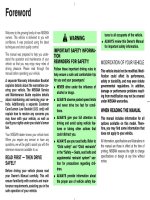
IMPORTANT SAFETY NOTICE
The proper performance of service is essential for both the safety of
the technician and the efficient functioning of the vehicle.
The service methods in this Service Manual are described in such a
manner that the service may be performed safely and accurately.
Service varies with the procedures used, the skills of the technician
and the tools and parts available. Accordingly, anyone using service
procedures, tools or parts which are not specifically recommended
by NISSAN must first be completely satisfied that neither personal
safety nor the vehicle’s safety will be jeopardized by the service
method selected.
Some works can be performed by GT-R certified NISSAN dealer only.
Check the works able to be performed at your dealership by refering
“Always read befor works”.
Your comments are important to NISSAN and will help us to improve our Service Manuals.
Use this form to report any issues or comments you may have regarding our Service Manuals.
Please print this form and type or write your comments below. Mail or fax to:
Nissan North America, Inc.
Technical Service Information
39001 Sunrise Drive, P.O. Box 9200
Farmington Hills, MI USA 48331
FAX: (248) 488-3880
SERVICE MANUAL: Model: Year:
PUBLICATION NO. (Refer to Quick Reference Index ):
Please describe any Service Manual issues or problems in detail:
Page number(s)
Note: Please include a copy of each page, marked with your comments.
Are the trouble diagnosis procedures logical and easy to use? (circle your answer) YES NO
If no, what page number(s)?
Note: Please include a copy of each page, marked with your comments.
Please describe the issue or problem in detail:
Is the organization of the manual clear and easy to follow? (circle your answer) YES NO
Please comment:
What information should be included in NISSAN Service Manuals to better support you in servicing or
repairing customer vehicles?
DATE: YOUR NAME: POSITION:
DEALER: DEALER NO.: ADDRESS:
CITY: STATE/PROV./COUNTRY: ZIP/POSTAL CODE:
QUICK REFERENCE CHART GT-R
QUICK REFERENCE CHART GT-R PFP:00000
ENGINE TUNE-UP DATA (VR38DETT) ELS0003W
Engine model VR38DETT
Firing order 1-2-3-4-5-6
Idle speed
(In “P” or “N” position)
rpm
825 ± 50
Ignition timing
(BTDC at idle speed)
27° ± 5°
Tensions of drive belt Auto adjustment by auto tensioner
Reservoir tank cap relief pressure
kPa (kg/cm
2
, psi)
Standard 122.3 - 151.7 (1.2 - 1.5, 18 - 22)
Limit 107 (1.1, 16)
Cooling system leakage testing pressure
kPa (kg/cm
2
, psi)
157 (1.6, 23)
Compression pressure
kPa (kg/cm
2
, psi)/rpm
Standard 970 (9.89, 141)/200
Minimum 800 (8.16, 116)/200
Differential limit between cylinders 100 (1.02, 14.5)/200
Spark plug
(Iridium-tipped type)
Make NGK
Standard type DILKAR8A8
Gap (Nominal) mm (in) 0.7 - 0.8 (0.028 - 0.031)
2014
QUICK REFERENCE CHART GT-R
FRONT WHEEL ALIGNMENT
EXCEPT TRACK PACK-SPECIFIC SUSPENSION
CAMBER, TOE-IN
Setting guide depending on the customer’s driving
• Adjust wheel alignment to the customer’s driving style.
• Never set to toe-out.
- Always adjust to toe-in. If the wheels change to toe-out, tire partial wear is accelerated and local heating may
be accelerated in the inner side of tires.
- Always adjust toe-in to 1.5 mm (0.059 in) or less because too much toe-in may promote local heat genera-
tion.
- For the above reasons, always adjust to toe-in for the vehicle of a customer who drives on a racetrack.
- Engaging in performance driving on a racetrack and ultra-high-speed driving, be sure to adjust toe-in to 1.5
mm (0.059 in) or less. If used beyond this range, it is not covered by the warranty.
• When driving on a racetrack, recommend to adjust the alignment to the “Performance driving on a racetrack”
setting. If the negative camber angle is insufficient driving on a technical course including many tight turns
may result in wear on the outside of the tire and this can cause an accident. [To avoid uneven wear, servicing
the vehicle after performance driving (at the customer's expense) is recommended to result the alignment to
the original setting.]
• Wheel alignment can be changed in process of time and mileage, as suspension parts do not adjust to each
other up to the mileage of about 1,000 miles or 2,000 km.
• Remarks for up to the mileage of 1,000 miles or 2,000 km
- Camber angle NG zone (positive side): −1°20′ (−1.33°)
- Toe angle of one-side wheel: See reference value.
JSEIA0633GB
2014
QUICK REFERENCE CHART GT-R
CASTER, KINGPIN INCLINATION
Measure value under unladen
*
conditions.
*: Fuel, engine coolant and lubricant are full. Jack, hand tools and mats are in designated positions.
• Wheel alignment can be changed in process of time and mileage, as suspension parts do not adjust to each
other up to the mileage of about 1,000 miles or 2,000 km.
TRACK PACK-SPECIFIC SUSPENSION
CAMBER, TOE-IN
Setting guide depending on the customer’s driving
• Adjust wheel alignment to the customer’s driving style.
• Never set to toe-out.
- Always adjust to toe-in. If the wheels change to toe-out, tire partial wear is accelerated and local heating may
be accelerated in the inner side of tires.
- Always adjust toe-in to 1.5 mm (0.059 in) or less because too much toe-in may promote local heat genera-
tion.
- For the above reasons, always adjust to toe-in for the vehicle of a customer who drives on a racetrack.
- Engaging in performance driving on a racetrack and ultra-high-speed driving, be sure to adjust toe-in to 1.5
mm (0.059 in) or less. If used beyond this range, it is not covered by the warranty.
• Insufficient negative camber during hard cornering on a racetrack may result in tire wear. Therefore, recom-
mend the customer to adjust negative camber angle in the negative direction when driving on a racetrack.
[To avoid uneven wear, recommend the customer to have the camber angle aligned in the positive direction
at an inspection after performance driving (at customer's expense).]
• Wheel alignment can be changed in process of time and mileage, as suspension parts do not adjust to each
other up to the mileage of about 1,000 miles or 2,000 km.
Item Standard
Caster
Degree minute (Decimal degree)
Minimum 5° 40′ (5.67°)
Nominal 6° 00′ (5.00°)
Maximum 6° 40′ (6.66°)
Left and right difference 0° 30′ (0.50°) or less
Kingpin inclination
Degree minute (Decimal degree)
Minimum 9° 20′ (9.34°)
Nominal 9° 30′ (9.50°)
Maximum 9° 40′ (9.66°)
JSEIA0634GB
2014
QUICK REFERENCE CHART GT-R
• Remarks for up to the mileage of 1,000 miles or 2,000 km
- Toe angle of one-side wheel: See reference value.
• Each part of the suspension may not conform during a normal driving because of the adoption of a hard rate
coil spring and a high damping shock absorber.
CASTER, KINGPIN INCLINATION
Measure value under unladen
*
conditions.
*: Fuel, engine coolant and lubricant are full. Jack, hand tools and mats are in designated positions.
• Wheel alignment can be changed in process of time and mileage, as suspension parts do not adjust to each
other up to the mileage of about 1,000 miles or 2,000 km.
• Each part of the suspension may not conform during a normal driving because of the adoption of a hard rate
coil spring and a high damping shock absorber.
Item Standard
Caster
Degree minute (Decimal degree)
Minimum 5° 45′ (5.75°)
Nominal 6° 05′ (6.08°)
Maximum 6° 45′ (6.75°)
Left and right difference 0° 30′ (0.50°) or less
Kingpin inclination
Degree minute (Decimal degree)
Minimum 9° 30′ (9.50°)
Nominal 9° 40′ (9.67°)
Maximum 9° 50′ (9.83°)
2014
QUICK REFERENCE CHART GT-R
REAR WHEEL ALIGNMENT
EXCEPT TRACK PACK-SPECIFIC SUSPENSION
CAMBER, TOE-IN
Setting guide depending on the customer’s driving
• Adjust wheel alignment to the customer’s driving style.
• Never set to toe-out.
- Always adjust to toe-in. If the wheels change to toe-out, tire partial wear is accelerated and local heating may
be accelerated in the inner side of tires.
- For the above reasons, always adjust to toe-in for the vehicle of a customer who drives on a racetrack.
- Engaging in performance driving on a racetrack and ultra-high-speed driving, be sure to adjust toe-in to 2.0
mm (0.079 in) or less. If used beyond this range, it is not covered by the warranty.
• When driving on a racetrack, recommend to adjust the alignment to the “Performance driving on a racetrack”
setting. If the negative camber angle is insufficient driving on a technical course including many tight turns
may result in wear on the outside of the tire and this can cause an accident. [To avoid uneven wear, servicing
the vehicle after performance driving (at the customer's expense) is recommended to result the alignment to
the original setting.]
• Wheel alignment can be changed in process of time and mileage, as suspension parts do not adjust to each
other up to the mileage of about 1,000 miles or 2,000 km.
• Remarks for up to the mileage of 1,000 miles or 2,000 km
- Toe angle of one-side wheel: See reference value.
JSEIA0487GB
2014
QUICK REFERENCE CHART GT-R
TRACK PACK-SPECIFIC SUSPENSION
CAMBER, TOE-IN
Setting guide depending on the customer’s driving
• Adjust wheel alignment to the customer’s driving style.
• Never set to toe-out.
- Always adjust to toe-in. If the wheels change to toe-out, tire partial wear is accelerated and local heating may
be accelerated in the inner side of tires.
- For the above reasons, always adjust to toe-in for the vehicle of a customer who drives on a racetrack.
- Engaging in performance driving on a racetrack and ultra-high-speed driving, be sure to adjust toe-in to 2.0
mm (0.079 in) or less. If used beyond this range, it is not covered by the warranty.
• Insufficient negative camber during hard cornering on a racetrack may result in tire wear. Therefore, recom-
mend the customer to adjust negative camber angle in the negative direction when driving on a racetrack.
[To avoid uneven wear, recommend the customer to have the camber angle aligned in the positive direction
at an inspection after performance driving (at customer's expense).]
• Wheel alignment can be changed in process of time and mileage, as suspension parts do not adjust to each
other up to the mileage of about 1,000 miles or 2,000 km.
• Remarks for up to the mileage of 1,000 miles or 2,000 km
- Toe angle of one-side wheel: See reference value.
• Each part of the suspension may not conform during a normal driving because of the adoption of a hard rate
coil spring and a high damping shock absorber.
JSEIA0635GB
2014
QUICK REFERENCE CHART GT-R
BRAKE PEDAL
Unit: mm (in.)
FRONT DISC BRAKE
Unit: mm (in.)
REAR DISC BRAKE
Unit: mm (in.)
REFILL CAPACITIES ELS00040
Item Standard
Brake pedal height 169.0 – 179.0 (6.65 – 7.05)
Clearance between the stop lamp switch and ASCD brake switch threaded end and
the stopper rubber
0.2 – 1.96 (0.008 – 0.0772)
Brake pedal play 3.0 – 11.0 (0.118 – 0.433)
Depressed brake pedal height
[Depressing 490 N (50 kg, 110 lb) while turning the engine ON]
100 (3.94) or more
Item Limit
Brake pad Wear thickness 4.5 (0.177)
Disc rotor Wear thickness 30.6 (1.205)
Item Limit
Brake pad Wear thickness 4.5 (0.177)
Disc rotor Wear thickness 28.0 (1.102)
UNIT Liter US measure
Fuel tank 73.8 19-1/2 gal
Engine Coolant (With reservoir tank at MAX level) 11.3 12 qt
Engine oil
Drain and refill
With oil filter change 5.0 5-1/4 qt
Without oil filter change 4.5 4-3/4 qt
Dry engine (Overhaul) 6.2 6-4/8 qt
Transmission 9.4 9-7/8 qt
Final drive
Front 0.65 1-3/8 pt
Rear 1.35 2-7/8 pt
Power steering system 1.0 1-1/8 qt
Air conditioning system
Compressor oil 0.15 5.07 fl oz
Refrigerant 0.5 kg 1.1 lb
2014
IP-1
BODY INTERIOR
C
D
E
F
G
H
I
K
L
M
SECTION IP
A
B
IP
N
O
P
CONTENTS
INSTRUMENT PANEL
PRECAUTION 2
PRECAUTIONS 2
Precaution for Supplemental Restraint System
(SRS) "AIR BAG" and "SEAT BELT PRE-TEN-
SIONER" 2
Precautions Necessary for Steering Wheel Rota-
tion After Battery Disconnection 2
Precaution for Battery Service 3
Precaution 3
PREPARATION 4
PREPARATION 4
Special Service Tools 4
Commercial Service Tools 4
CLIP LIST 5
Clip List 5
SYMPTOM DIAGNOSIS 6
SQUEAK AND RATTLE TROUBLE DIAG-
NOSES 6
Work Flow 6
Inspection Procedure 8
Diagnostic Worksheet 10
REMOVAL AND INSTALLATION 12
INSTRUMENT PANEL ASSEMBLY 12
Exploded View 12
Removal and Installation 13
CENTER CONSOLE ASSEMBLY 23
Exploded View 23
Removal and Installation 23
Disassembly and Assembly 25
Revision: 2012 November 2014 GT-R
IP-2
< PRECAUTION >
PRECAUTIONS
PRECAUTION
PRECAUTIONS
Precaution for Supplemental Restraint System (SRS) "AIR BAG" and "SEAT BELT
PRE-TENSIONER" INFOID:0000000009162785
The Supplemental Restraint System such as “AIR BAG” and “SEAT BELT PRE-TENSIONER”, used along
with a front seat belt, helps to reduce the risk or severity of injury to the driver and front passenger for certain
types of collision. This system includes seat belt switch inputs and dual stage front air bag modules. The SRS
system uses the seat belt switches to determine the front air bag deployment, and may only deploy one front
air bag, depending on the severity of a collision and whether the front occupants are belted or unbelted.
Information necessary to service the system safely is included in the “SRS AIR BAG” and “SEAT BELT” of this
Service Manual.
WARNING:
Always observe the following items for preventing accidental activation.
• To avoid rendering the SRS inoperative, which could increase the risk of personal injury or death in
the event of a collision that would result in air bag inflation, all maintenance must be performed by
an authorized NISSAN/INFINITI dealer.
• Improper maintenance, including incorrect removal and installation of the SRS, can lead to personal
injury caused by unintentional activation of the system. For removal of Spiral Cable and Air Bag
Module, see “SRS AIR BAG”.
• Never use electrical test equipment on any circuit related to the SRS unless instructed to in this Ser-
vice Manual. SRS wiring harnesses can be identified by yellow and/or orange harnesses or harness
connectors.
PRECAUTIONS WHEN USING POWER TOOLS (AIR OR ELECTRIC) AND HAMMERS
WARNING:
Always observe the following items for preventing accidental activation.
• When working near the Air Bag Diagnosis Sensor Unit or other Air Bag System sensors with the
ignition ON or engine running, never use air or electric power tools or strike near the sensor(s) with
a hammer. Heavy vibration could activate the sensor(s) and deploy the air bag(s), possibly causing
serious injury.
• When using air or electric power tools or hammers, always switch the ignition OFF, disconnect the
battery, and wait at least 3 minutes before performing any service.
Precautions Necessary for Steering Wheel Rotation After Battery Disconnection
INFOID:0000000009162786
CAUTION:
Comply with the following cautions to prevent any error and malfunction.
• Before removing and installing any control units, first turn the ignition switch to the LOCK position,
then disconnect both battery cables.
• After finishing work, confirm that all control unit connectors are connected properly, then re-connect
both battery cables.
• Always use CONSULT to perform self-diagnosis as a part of each function inspection after finishing
work. If a DTC is detected, perform trouble diagnosis according to self-diagnosis results.
For vehicle with steering lock unit, if the battery is disconnected or discharged, the steering wheel will lock and
cannot be turned.
If turning the steering wheel is required with the battery disconnected or discharged, follow the operation pro-
cedure below before starting the repair operation.
OPERATION PROCEDURE
1. Connect both battery cables.
NOTE:
Supply power using jumper cables if battery is discharged.
2. Turn the ignition switch to ACC position.
(At this time, the steering lock will be released.)
3. Disconnect both battery cables. The steering lock will remain released with both battery cables discon-
nected and the steering wheel can be turned.
Revision: 2012 November 2014 GT-R
PRECAUTIONS
IP-3
< PRECAUTION >
C
D
E
F
G
H
I
K
L
M
A
B
IP
N
O
P
4. Perform the necessary repair operation.
5. When the repair work is completed, re-connect both battery cables. With the brake pedal released, turn
the ignition switch from ACC position to ON position, then to LOCK position. (The steering wheel will lock
when the ignition switch is turned to LOCK position.)
6. Perform self-diagnosis check of all control units using CONSULT.
Precaution for Battery Service INFOID:0000000009162787
Before disconnecting the battery, lower both the driver and passenger windows. This will prevent any interfer-
ence between the window edge and the vehicle when the door is opened/closed. During normal operation, the
window slightly raises and lowers automatically to prevent any window to vehicle interference. The automatic
window function will not work with the battery disconnected.
Precaution INFOID:0000000009162788
• Disconnect battery negative terminal in advance.
• Disconnect air bag system line in advance.
• Never tamper with or force air bag lid open, as this may adversely affect air bag performance.
• Be careful not to scratch pad and other parts.
• When removing or disassembling any part, be careful not to damage or deform it. Protect parts that may get
in the way with a shop cloth.
• When removing parts with a screwdriver or other tool, cover the tool surface by using vinyl tape to protect
parts.
• Keep removed parts protected with a shop cloth.
• If a clip is deformed or damaged, replace it.
• If an unreusable part is removed, replace it with a new one.
• Tighten bolts and nuts firmly to the specified torque.
• After reassembly is complete, check that each part functions correctly.
• Remove stains in the following way.
Water-soluble stains:
Dip a soft cloth in warm water, and then squeeze it tightly. After wiping the stain, wipe with a soft dry cloth.
Oil stain:
Dissolve a synthetic detergent in warm water (density of 2 to 3%), dip the cloth, then clean off the stain with
the cloth. Next, dip the cloth in fresh water and squeeze it tightly. Then clean off the detergent completely.
Finally, wipe the area with a soft dry cloth.
• Never use any organic solvent, such as thinner or benzine.
Revision: 2012 November 2014 GT-R
IP-4
< PREPARATION >
PREPARATION
PREPARATION
PREPARATION
Special Service Tools INFOID:0000000009162789
The actual shapes of Kent-Moore tools may differ from those of special service tools illustrated here.
Commercial Service Tools INFOID:0000000009162790
Tool number
(Kent-Moore No.)
Tool name
Description
(J-39570)
Chassis ear
Locates the noise
(J-43980)
NISSAN Squeak and Rattle Kit
Repairs the cause of noise
SIIA0993E
SIIA0994E
Tool name Description
Engine ear Locates the noise
Remover tool Removes clips, pawls, and metal clips
Power tool
SIIA0995E
JMKIA3050ZZ
PIIB1407E
Revision: 2012 November 2014 GT-R
CLIP LIST
IP-5
< PREPARATION >
C
D
E
F
G
H
I
K
L
M
A
B
IP
N
O
P
CLIP LIST
Clip List INFOID:0000000009162791
JMJIA3734GB
Revision: 2012 November 2014 GT-R
IP-6
< SYMPTOM DIAGNOSIS >
SQUEAK AND RATTLE TROUBLE DIAGNOSES
SYMPTOM DIAGNOSIS
SQUEAK AND RATTLE TROUBLE DIAGNOSES
Work Flow INFOID:0000000009162792
CUSTOMER INTERVIEW
Interview the customer if possible, to determine the conditions that exist when the noise occurs. Use the Diag-
nostic Worksheet during the interview to document the facts and conditions when the noise occurs and any of
customer's comments; refer to IP-10, "Diagnostic Worksheet". This information is necessary to duplicate the
conditions that exist when the noise occurs.
• The customer may not be able to provide a detailed description or the location of the noise. Attempt to obtain
all the facts and conditions that exist when the noise occurs (or does not occur).
• If there is more than one noise in the vehicle, perform a diagnosis and repair the noise that the customer is
concerned about. This can be accomplished by performing a cruise test on the vehicle with the customer.
• After identifying the type of noise, isolate the noise in terms of its characteristics. The noise characteristics
are provided so the customer, service adviser and technician are all speaking the same language when
defining the noise.
• Squeak – (Like tennis shoes on a clean floor)
Squeak characteristics include the light contact/fast movement/brought on by road conditions/hard surfaces
= higher pitch noise/softer surfaces = lower pitch noises/edge to surface = chirping
• Creak – (Like walking on an old wooden floor)
Creak characteristics include firm contact/slow movement/twisting with a rotational movement/pitch depen-
dent on materials/often brought on by activity.
• Rattle – (Like shaking a baby rattle)
Rattle characteristics include the fast repeated contact/vibration or similar movement/loose parts/missing
clip or fastener/incorrect clearance.
• Knock – (Like a knock on a door)
Knock characteristics include hollow sounding/sometimes repeating/often brought on by driver action.
• Tick – (Like a clock second hand)
Tick characteristics include gentle contacting of light materials/loose components/can be caused by driver
action or road conditions.
• Thump – (Heavy, muffled knock noise)
Thump characteristics include softer knock/dead sound often brought on by activity.
• Buzz – (Like a bumblebee)
Buzz characteristics include high frequency rattle/firm contact.
• Often the degree of acceptable noise level will vary depending up on the person. A noise that a technician
may judge as acceptable may be very irritating to the customer.
• Weather conditions, especially humidity and temperature, may have a great effect on noise level.
DUPLICATE THE NOISE AND TEST DRIVE
SBT842
Revision: 2012 November 2014 GT-R
SQUEAK AND RATTLE TROUBLE DIAGNOSES
IP-7
< SYMPTOM DIAGNOSIS >
C
D
E
F
G
H
I
K
L
M
A
B
IP
N
O
P
If possible, drive the vehicle with the customer until the noise is duplicated. Note any additional information on
the Diagnostic Worksheet regarding the conditions or location of the noise. This information can be used to
duplicate the same conditions when the repair is reconfirmed.
If the noise can be duplicated easily during the test drive, to help identify the source of the noise, try to dupli-
cate the noise with the vehicle stopped by doing one or all of the following:
1) Close a door.
2) Tap or push/pull around the area where the noise appears to be coming from.
3) Rev the engine.
4) Use a floor jack to recreate vehicle “twist”.
5) At idle, apply engine load (electrical load, half-clutch on M/T models, drive position on A/T models).
6) Raise the vehicle on a hoist and hit a tire with a rubber hammer.
• Drive the vehicle and attempt to duplicate the conditions the customer states exist when the noise occurs.
• If it is difficult to duplicate the noise, drive the vehicle slowly on an undulating or rough road to stress the
vehicle body.
CHECK RELATED SERVICE BULLETINS
After verifying the customer concern or symptom, check ASIST for Technical Service Bulletins (TSBs) related
to that concern or symptom.
If a TSB relates to the symptom, follow the procedure to repair the noise.
LOCATE THE NOISE AND IDENTIFY THE ROOT CAUSE
1. Narrow down the noise to a general area. To help pinpoint the source of the noise, use a listening tool
(Chassis ear: J-39570, Engine ear and mechanics stethoscope).
2. Narrow down the noise to a more specific area and identify the cause of the noise by:
• Removing the components in the area that is are suspected to be the cause of the noise.
Do not use too much force when removing clips and fasteners, otherwise clips and fastener can be broken
or lost during the repair, resulting in the creation of new noise.
• Tapping or pushing/pulling the component that is are suspected to be the cause of the noise.
Do not tap or push/pull the component with excessive force, otherwise the noise will be eliminated only tem-
porarily.
• Feeling for a vibration by hand by touching the component(s) that is are suspected to be the cause of the
noise.
• Placing a piece of paper between components that are suspected to be the cause of the noise.
• Looking for loose components and contact marks.
Refer to IP-8, "
Inspection Procedure".
REPAIR THE CAUSE
• If the cause is a loose component, tighten the component securely.
• If the cause is insufficient clearance between components:
- Separate components by repositioning or loosening and retightening the component, if possible.
- Insulate components with a suitable insulator such as urethane pads, foam blocks, felt cloth tape or ure-
thane tape. A Nissan Squeak and Rattle Kit (J-43980) is available through the authorized Nissan Parts
Department.
CAUTION:
Never use excessive force as many components are constructed of plastic and may be damaged.
NOTE:
Always check with the Parts Department for the latest parts information.
The following materials are contained in the Nissan Squeak and Rattle Kit (J-43980). Each item can be
ordered separately as needed.
URETHANE PADS [1.5 mm (0.059 in) thick]
Insulates connectors, harness, etc.
• 76268-9E005: 100 × 135 mm (3.937 × 5.315 in)
• 76884-71L01: 60 × 85 mm (2.362 × 3.346 in)
• 76884-71L02:15 × 25 mm (0.591 × 0.984 in)
INSULATOR (Foam blocks)
Insulates components from contact. Can be used to fill space behind a panel.
• 73982-9E000: 45 mm (1.772 in) thick, 50 × 50 mm (1.969 × 1.969 in)
• 73982-50Y00: 10 mm (0.394 in) thick, 50 × 50 mm (1.969 × 1.969 in)
INSULATOR (Light foam block)
• 80845-71L00: 30 mm (1.181 in) thick, 30 × 50 mm (1.181 × 1.969in)
FELT CLOTHTAPE
Revision: 2012 November 2014 GT-R
IP-8
< SYMPTOM DIAGNOSIS >
SQUEAK AND RATTLE TROUBLE DIAGNOSES
Used to insulate where movement does not occur. Ideal for instrument panel applications.
• 68370-4B000: 15 × 25 mm (0.59 × 0.984 in) pad
• 68239-13E00: 5 mm (0.197 in) wide tape roll
The following materials, not found in the kit, can also be used to repair squeaks and rattles.
UHMW (TEFLON) TAPE
Insulates where slight movement is present. Ideal for instrument panel applications.
SILICONE GREASE
Used in place of UHMW tape that is be visible or does not fit. Will only last a few months.
SILICONE SPRAY
Used when grease cannot be applied.
DUCT TAPE
Used to eliminate movement.
CONFIRM THE REPAIR
Confirm that the cause of a noise is repaired by test driving the vehicle. Operate the vehicle under the same
conditions as when the noise originally occurred. Refer to the notes on the Diagnostic Worksheet.
Inspection Procedure INFOID:0000000009162793
Refer to Table of Contents for specific component removal and installation information.
INSTRUMENT PANEL
Most incidents are caused by contact and movement between:
1. The cluster lid A and instrument panel
2. Acrylic lens and combination meter housing
3. Instrument panel to front pillar garnish
4. Instrument panel to windshield
5. Instrument panel mounting pins
6. Wiring harnesses behind the combination meter
7. A/C defroster duct and duct joint
These incidents can usually be located by tapping or moving the components to duplicate the noise or by
pressing on the components while driving to stop the noise. Most of these incidents can be repaired by
applying felt cloth tape or silicon spray (in hard to reach areas). Urethane pads can be used to insulate
wiring harness.
CAUTION:
Never use silicone spray to isolate a squeak or rattle. If the area is saturated with silicone, the
recheck of repair becomes impossible.
CENTER CONSOLE
Components to pay attention to include:
1. Shifter assembly cover to finisher
2. A/C control unit and cluster lid C
3. Wiring harnesses behind audio and A/C control unit
The instrument panel repair and isolation procedures also apply to the center console.
DOORS
Pay attention to the following:
1. Finisher and inner panel making a slapping noise
2. Inside handle escutcheon to door finisher
3. Wiring harnesses tapping
4. Door striker out of alignment causing a popping noise on starts and stops
Tapping or moving the components or pressing on them while driving to duplicate the conditions can isolate
many of these incidents. The areas can usually be insulated with felt cloth tape or insulator foam blocks from
the Nissan Squeak and Rattle Kit (J-43980) to repair the noise.
TRUNK
Trunk noises are often caused by a loose jack or loose items put into the trunk by the customer.
In addition look for the following:
1. Trunk lid dumpers out of adjustment
Revision: 2012 November 2014 GT-R
SQUEAK AND RATTLE TROUBLE DIAGNOSES
IP-9
< SYMPTOM DIAGNOSIS >
C
D
E
F
G
H
I
K
L
M
A
B
IP
N
O
P
2. Trunk lid striker out of adjustment
3. The trunk lid torsion bars knocking together
4. A loose license plate or bracket
Most of these incidents can be repaired by adjusting, securing or insulating the item(s) or component(s) caus-
ing the noise.
SUNROOF/HEADLINING
Noises in the sunroof/headlining area can often be traced to one of the following:
1. Sunroof lid, rail, linkage or seals making a rattle or light knocking noise
2. Sunvisor shaft shaking in the holder
3. Front or rear windshield touching headlining and squeaking
Again, pressing on the components to stop the noise while duplicating the conditions can isolate most of these
incidents. Repairs usually consist of insulating with felt cloth tape.
SEATS
When isolating seat noise it's important to note the position the seats in and the load placed on the seat when
the noise occurs. These conditions should be duplicated when verifying and isolating the cause of the noise.
Cause of seat noise include:
1. Headrest rods and holder
2. A squeak between the seat pad cushion and frame
3. The rear seatback lock and bracket
These noises can be isolated by moving or pressing on the suspected components while duplicating the con-
ditions under which the noise occurs.Most of these incidents can be repaired by repositioning the component
or applying urethane tape to the contact area.
UNDERHOOD
Some interior noise may be caused by components under the hood or on the engine wall. The noise is then
transmitted into the passenger compartment.
Causes of transmitted underhood noise include:
1. Any component mounted to the engine wall
2. Components that pass through the engine wall
3. Engine wall mounts and connectors
4. Loose radiator mounting pins
5. Hood bumpers out of adjustment
6. Hood striker out of adjustment
These noises can be difficult to isolate since they cannot be reached from the interior of the vehicle. The best
method is to secure, move or insulate one component at a time and test drive the vehicle. Also, engine RPM
or load can be changed to isolate the noise. Repairs can usually be made by moving, adjusting, securing, or
insulating the component causing the noise.
Revision: 2012 November 2014 GT-R
IP-10
< SYMPTOM DIAGNOSIS >
SQUEAK AND RATTLE TROUBLE DIAGNOSES
Diagnostic Worksheet
INFOID:0000000009162794
PIIB8740E
Revision: 2012 November 2014 GT-R
SQUEAK AND RATTLE TROUBLE DIAGNOSES
IP-11
< SYMPTOM DIAGNOSIS >
C
D
E
F
G
H
I
K
L
M
A
B
IP
N
O
P
PIIB8742E
Revision: 2012 November 2014 GT-R
IP-12
< REMOVAL AND INSTALLATION >
INSTRUMENT PANEL ASSEMBLY
REMOVAL AND INSTALLATION
INSTRUMENT PANEL ASSEMBLY
Exploded View INFOID:0000000009162795
JMJIA2175ZZ
Revision: 2012 November 2014 GT-R
INSTRUMENT PANEL ASSEMBLY
IP-13
< REMOVAL AND INSTALLATION >
C
D
E
F
G
H
I
K
L
M
A
B
IP
N
O
P
Removal and Installation INFOID:0000000009162796
Work item table
1. Sunload sensor 2. Front defroster grille RH 3. Front defroster grille LH
4. Security indicator 5. Center speaker grille 6. Center speaker
7. Instrument panel assembly 8. Instrument side finisher LH 9. Instrument pad A
10. Side ventilator grille LH 11. Mirror control switch 12. Instrument pad B
13. Cluster lid A 14. Steering column upper cover 15. Steering column side cover LH
16. Steering column mask LH 17. Instrument lower panel (driver) 18. Cluster lid C (lower)
19. Instrument lower cover LH 20. Glove box assembly 21. Instrument lower panel (assist)
22. Globe box damper 23. Side ventilator grille RH 24. Instrument pad C
25. Instrument side finisher RH 26. Display unit 27. Center ventilator grille LH
28. Steering column front lower cover 29. Steering column lower cover 30. Steering column mask RH
31. AV C/U 32. Set-up switch assembly 33. Socket & bulb
34. Instrument garnish RH 35. Center ventilator grille RH 36. A/C auto amp.
37. Multifunction switch 38. Cluster lid C (upper) 39. Instrument garnish LH
40. Steering column side cover RH 41. Preset switch assembly 42. Instrument garnish (upper)
PARTS
INSTRUMENT
PANEL
ASSEMBLY
COMBINATION
METER
DISPLAY UNIT AV control unit
CENTER
CONSOLE
ASSEMBLY
Rear console assembly [1] [1]
Instrument garnish LH [2] [1] [1] [2]
Instrument garnish RH [3] [2] [2] [3]
Console finisher assembly [4] [3] [4]
Instrument side panel LH [5] [5]
Instrument side panel RH [6] [6]
Center console assembly [7] [7]
A/T shift selector assembly [8]
Preset switch assembly [9] [3] [4]
Set-up switch assembly [10] [5]
Cluster lid C (lower) [11] [6]
AV control unit [12] [7]
A/C auto amp. [13]
Instrument side finisher LH [14]
Body side welt LH [15]
Front pillar garnish LH [16]
Instrument lower panel (driver) [17]
Driver air bag module [18] [1] [4]
Steering wheel [19] [2] [5]
Steering column front lower cover [20] [3] [6]
Steering column cover [21] [4] [7]
Combination switch [22] [5] [8]
Cluster lid A [23] [6] [9]
Power socket [24]
Instrument pad A [25] [10]
Display unit [26] [11]
Revision: 2012 November 2014 GT-R
IP-14
< REMOVAL AND INSTALLATION >
INSTRUMENT PANEL ASSEMBLY
[ ]: Number indicates step in removal procedure.
WARNING:
Before servicing, turn ignition switch OFF, disconnect battery negative terminal and wait 3 minutes or
more.
CAUTION:
When removing, always use a remover tool that is made of plastic.
REMOVAL
1. Remove rear console assembly.
1. Lift up rear side of rear console assembly (1), and then dis-
engage pawls and metal clips.
2. Disconnect harness connector on the back.
2. Remove instrument garnish LH.
1. Insert remover tool (A), wrapped in a shop cloth, into clear-
ance between lower side of instrument garnish LH (1) and
cluster lid C (lower) (2).
2. Pull back instrument garnish LH, and then disengage pawls.
3. Remove instrument garnish RH.
Instrument pad B [27]
Front defroster grille LH [28]
Center speaker grille [29]
Center speaker [30]
Front defroster grille RH [31]
Instrument side finisher RH [32]
Body side welt RH [33]
Front pillar garnish RH [34]
Glove box lid [35]
Instrument lower cover RH [36]
Instrument lower panel (assist) [37]
Instrument pad C [38]
Instrument panel assembly [39]
PARTS
INSTRUMENT
PANEL
ASSEMBLY
COMBINATION
METER
DISPLAY UNIT AV control unit
CENTER
CONSOLE
ASSEMBLY
: Pawl
: Metal clip
NNJIA0052ZZ
: Pawl
JMJIA2177ZZ
Revision: 2012 November 2014 GT-R