Bishop lecture Advanced laboratory testing in research and practice
Bạn đang xem bản rút gọn của tài liệu. Xem và tải ngay bản đầy đủ của tài liệu tại đây (1.99 MB, 20 trang )
35
Proceedings of the 18
th
International Conference on Soil Mechanics and Geotechnical Engineering, Paris 2013
1
Bishop lecture
Advanced laboratory testing in research and practice
Conférence Bishop
Les essais en laboratoire avancés dans la recherche et dans l'industrie
Jardine R. J.
Imperial College London, UK
ABSTRACT: This lecture demonstrates the special capabilities and practical value of Advanced Laboratory Testing, focusing on its
application in advancing the understanding and prediction of how driven piles function and perform in sand. Emphasis is placed on
integrating laboratory research with analysis and field observations, drawing principally on work by the Author, his colleagues an
d
research group. The laboratory studies include highly instrumented static and cyclic stress-
p
ath triaxial experiments, hollow cylinde
r
and ring-shear interface tests and micro-mechanical research. Soil element testing is combined with model studies in large laboratory
calibration chambers, full-scale field investigations and numerical simulations to help advance fundamental methods for predicting pile
behaviour that have important implications and applications, particularly in offshore engineering.
RÉSUMÉ: Cet exposé décrit les possibilités offertes par les essais en laboratoire de pointe, et en particulier sur leurs apports dans l
a
compréhension et la prévision du comportement des pieux battus dans du sable. L'accent est mis sur l’intégration entre les essais en
laboratoire et les observations sur le terrain, à partir des travaux de l'Auteur, ses collègues et leur groupe de recherche. Les essais décris
incluent des essais triaxiaux statiques et cycliques avec des appareils suréquipés, des essais au triaxial à cylindre creux, des études
d'interfaces pieu/sable à l'aide d'appareils de cisaillement annulaire et des recherches sur la micro-mécanique. Les essais en laboratoire
sont combinés à des expériences en chambre de calibration, des études « grandeur nature » sur site et des simulations numériques afin
d'aider à l'amélioration des méthodes de prévision du comportement des pieux, qui ont des conséquences importantes en pratique,
notamment pour l'industrie offshore.
KEYWORDS: Sand; laboratory element tests; non-linearity anisotropy breakage time-dependence; driven piles; field and model tests
MOTS-CLÉS: Sable ; tests élémentaires en laboratoire; non-linearité, anisotropie, fragmentation; comportement en fonction du temps;
pieu battu; pieu foncé; tests sur le terrain
1 INTRODUCTION
The Bishop Lecture was inaugurated by Technical Committee
TC-101 (formerly TC-29) of the ISSMGE, honouring the legacy
of Professor Alan Bishop (1920-1988), the leading figure of his
generation in geotechnical laboratory experiments and
equipment design. Bishop was well known for his meticulous
attention to detail, analytical rigour and application of
fundamental research in civil engineering practice. His
contributions to soil sampling and testing were summarised in
the last major keynote he gave, at the Stockholm ICSMFE;
Bishop 1981. Similarly admirable attributes were clear in the
first Bishop Lecture presented by Tatsuoka 2011, making the
invitation to deliver the 2
nd
Lecture both a considerable
challenge and a poignant honour for this former student of
Bishop and Skempton. The lives, work and archived papers of
the latter two pioneers are described together in a website hosted
by Imperial College: www.cv.ic.ac.uk/SkemArchive/index.htm.
Our key aim is to demonstrate the special capabilities and
practical value of Advanced Laboratory Testing, mirroring
Bishop’s work and TC-101’s intent in the International
Symposia (IS) it convened in Hokkaido 1994, London 1997,
Torino 1999, Lyon 2003, Atlanta 2008 and Seoul 2011. We
focus on the mechanics of piles driven in sand, a practical
problem that was thought fully resistant to ‘theoretical
refinement’ by Terzaghi and Peck 1967. The illustration draws
principally on work by the Author, his colleagues and research
group. In keeping with Bishop’s approach, emphasis is placed on
integrating laboratory research, analysis and field observation.
The selected topic is significant industrially. Pile stiffness,
capacity, cyclic response and long-term behaviour can be
critically important to, for example, wind-turbine foundations.
However, the key geomechanics issues are complex and cannot
be addressed fully or reliably with currently available
conventional design tools. Database studies and prediction
competitions have quantified the significant biases and scatters
associated with conventional practice. The Coefficients of
Variation (CoV) established by contrasting axial capacity
predictions with field tests typically fall around 0.5 to 0.7. Some
methods’ predictions scatter around half the measurements while
others tend to double the test values (Briaud and Tucker 1988).
The capacity CoVs can be halved and biases largely eliminated
by applying modern ‘offshore’ methods (Jardine et al 2005b,
Lehane et al 2005). But displacement predictions remain
unreliable under axial, lateral or moment loads. It is also unclear
how cyclic or extended loading should be considered: Kallehave
et al 2012, Jardine et al 2012. Improving understanding and
predictive ability will benefit a broad range of applications,
especially in offshore energy developments.
The Author’s research with displacement piles in sand
started with highly instrumented field model piles at Labenne
(SW France, Lehane et al 1993) and Dunkerque (N France,
Chow 1997), where full-scale testing followed. We review some
of the full-scale test results below before considering new
research prompted by some surprising and significant results.
The Dunkerque profile comprises medium-dense fine-to-
medium clean silica Holocene marine sand overlain by hydraulic
sand fill. Jardine et al 2006, Jardine and Standing 2012 and
Rimoy et al 2013 give details of the geotechnical profiles, pile
driving records and testing methods. Static and cyclic axial
loading tests were conducted on multiple piles, including six
19.3m long 457mm outside diameter driven steel pipe-piles: R1
to R6. Static axial testing involved a Maintained-Load (ML)
procedure where load (Q) was applied initially in 200 kN steps
that reduced as the tests progressed. Loads were held constant
Bishop Lecture
36
Proceedings of the 18
th
International Conference on Soil Mechanics and Geotechnical Engineering, Paris 2013
Proceedings of the 18
th
International Conference on Soil Mechanics and Geotechnical Engineering, Paris 2013
2
until creep rates slowed to pre-set limits; the piles took between
several hours and 1.5 days to reach failure. More rapid ML
tension tests that achieved failure with an hour were also
conducted after cyclic loading experiments. Testing rate was
found to affect displacements but have little influence on shaft
capacity. The cyclic tests were controlled to deliver
approximately sine-wave load variations at ≈ 1 cycle/minute.
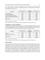
The static testing investigated, among other factors, the
effects of pile age after driving. Figure 1 presents tension tests
on three identical piles that were aged for 9 to 235 days before
being failed for the first time. We note:
The load displacement (Q – δ) curves are practically
identical up to Q ≈ 1 MN but then diverge to show marked
increases in Q
ult
(the ultimate load shaft capacity) with age.
Creep displacements (dδ/dt when dQ/dt = 0) were negligible
until Q > 1 MN after which creep became progressively
more important, finally dominating as failure approached.
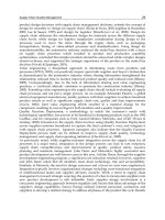
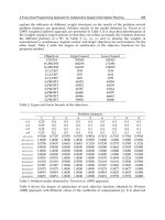
Load-displacement behaviour was highly non-linear. The
overall pile head secant stiffnesses k = Q/δ all fell as loading
continued with no discernible ‘linear-elastic’ plateau. This
feature is highlighted in Fig. 2 with data from ‘1
st
time’ tension
tests on five ‘R’ piles. The pile stiffnesses, k
l
, are normalised by
k
Ref
, the value developed under Q
Ref
- the first (200 kN) load
step. The loads Q are normalised by Q
Ref
.
Fig. 1. Load-displacement curves from first-time tension failures on
Dunkerque piles R1, R2 and R6: Jardine et al 2006
0 5 10 15 20
0.0
0.2
0.4
0.6
0.8
1.0
k
l
/k
Ref
Q/Q
Ref
R2 - R6
Fig. 2. Stiffness load-factor curves from 1
st
time tests at Dunkerque
conducted (except R6) around 80 days after driving: Rimoy et al 2013
An objective assessment was made of how well the
Dunkerque pile tests could be predicted by well-qualified
engineers by inviting entries to an open competition that
concentrated on the static and cyclic tests conducted ≈ 80 days
after driving; Jardine et al 2001a. Over 30 (many prominent)
international practitioners and academics took part, sending in a
wide spread of predictions. The axial capacity estimates
confirmed the expected CoV of 0.6, as well as significant bias;
the stiffness predictions were similarly spread.
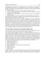
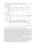
No competitor was prepared to predict the cyclic test
outcomes; some indicated that cycling should have no effect in
clean sand. Figure 3 illustrates the field outcomes in a cyclic
failure interaction diagram. The conditions under which 13 tests
ended in failure and one developed a fully stable response are
summarised by plotting the normalised cyclic load amplitude
Q
cyc
/Q
max static
against the average mid-cycle load Q
mean
/Q
max static
where Q
max static
= Q
T
current tension capacity. If cycling and
testing rate had no effect, then failures should lie on the ‘top-left
to bottom-right’ diagonal static capacity line: Q
cyc
+ Q
mean
= Q
T
in Fig. 3. However, the cyclic test failure points all fell well
below this limit, proving a negative impact that grew directly
with Q
cyc
/Q
mean
. High-level two-way (tension and compression)
cycling could halve shaft capacity within a few tens of cycles.
Rimoy et al 2013 discuss the piles’ permanent displacement
and cyclic stiffness trends, noting also that their non-linear cyclic
stiffnesses depended primarily on Q
cyc
/Q
T
and did not vary
greatly with the number of cycles (N) until failure approached.
The permanent displacement trends were more complex,
depending also on Q
mean
/Q
T
and N. Interactions were seen
between the piles’ ageing and cyclic behaviours: low-level
cycling accelerated capacity growth while high-level cycling
slowed or reversed the beneficial capacity trend.
Fig. 3. Axial cyclic interaction diagram for full–scale cyclic tests on piles
driven at Dunkerque: Jardine & Standing 2012
We consider below eight research themes that addressed the
shortfalls in understanding revealed by the Dunkerque tests:
1. Characterising the sands’ true stress-strain relationships,
correlating advanced laboratory and in-situ measurements.
2. Checking, through Finite Element (FE) modelling, whether
laboratory-based non-linear predictive approaches led to
better matches with full scale behaviour.
3. Stress-path laboratory testing programmes that investigated
creep and ageing trends.
4. Studying the stress conditions imposed by pile installation
through highly instrumented Calibration Chamber tests.
5. Grain-crushing and interface-shear zone studies involving
high pressure triaxial, ring-shear and laser particle analysis.
6. Quantitative checking against advanced numerical analyses.
37
Honour Lectures / Conférences honoriques
Proceedings of the 18
th
International Conference on Soil Mechanics and Geotechnical Engineering, Paris 2013
3
7. Model-pile Calibration Chamber cyclic loading experiments.
8.
Cyclic soil element tests to replicate pile loading conditions.
A common theme is that sands show strong non-linearity,
plasticity and time dependency fro
m very small strains and have
markedly anisotropic properties. It is argued that their overall
responses can be understood w
ithin a critical state soil
mechanics framework, provided that the above features are
accommodated and the importance of particle breakage is
recognised, especially under high
pressures and within abrading
shear bands. Space constraints limit the details that can be
reported for the various studies cite
d, or the reviews that can be
made of research by other group
s. However, PhD theses and co-
authored articles are cited to cover the main omissions.
2 CHARACTERISING STRESS-STRAIN BEHAVIOUR
Bishop recognised at an early stage that geotechnical stress-
strain measurements are constrained heavily by equipment
capabilities. ISSMGE Technical Committee 29 (now TC-101)
was set up to coordinate advan
ced laboratory developments,
leading to a review of apparatus,
sensors and testing strategies by
Tatsuoka et al 1999. The hydraulic stress path cells and Hollow
Cylinder Apparatus (HCA) advo
cated by Bishop and Wesley
1974 and Bishop 1981 allow in-situ stress conditions to be
imposed and studies made of shear strength anisotropy; see for
example Hight et al 1983 and Shib
uya et al 2003a,b. Burland and
Symes 1982 and Jardine et al 1984 went onto show that end-
bedding, sample tilting and compliance caused very large errors
in conventional geotechnical strain
measurements that often led
to completely misleading soil stiffness characteristics. Local
strain sensors or dynamic
non-destructive techniques are
required to obtain representative da
ta: see Tatsuoka et al 1999.
Laboratory research with such equipment that contributed to
the first phase of research that advanced the “Dunkerque
agenda” included the PhD studies of Porovic 1995, who worked
with a Resonant Column (RC) equipped HCA and Kuwano 1999
who developed dual-axis Bender
Elements (BE) and enhanced
resolution local strain sensors for stress-path triaxial tests.
Porovic worked mainly with Ham River Sand (HRS), a silica
sand graded from Thames Valley gravels that has been tested
since Bishop’s arrival at Impe
rial College and is now known
generically as Thames Valley Sand (TVS); Takahashi and
Jardine 2007. Kuwano studied Dunkerque sand, spherical glass
ballotini and HRS; Connol
ly 1998 undertook RC and HCA
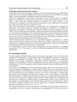
experiments on Dunkerque sand. The sands were tested saturated
after pluviation to the desired init
ial void ratios; Table 1 and Fig.
4 summarise their index properties. Figures 5 to 7 illustrate the
apparatus employed in this firs
t period of ‘sand’ research. We
consider studies with the Thames Valley (TVS) and French
Fontainebleau NE34 sands
later in the paper.
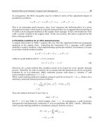
Table 1. Index properties of silica
sands employed in laboratory studies.
Sand
Specific
gravity (G
s
)
d
10
(mm)
d
50
(mm)
d
90
(mm)
C
u
e
max
e
min
Dunkerque
2.65 0.188 0.276 0.426 2.27 0.97 0.51
NE34
2.65 0.150 0.210 0.230 1.53 0.90 0.51
HRS
2.66 0.190 0.283 0.312 1.64 0.85 0.55
TVS 2.66 0.160 0.250 0.265 1.67 0.85 0.55
0.01 0.1 1 10
0
20
40
60
80
100
Percentage fine by weight (%)
Particle size (mm)
Dunkerque, Kuwano(1999)
new-HRS Kuwano (1999)
NE34, Yang et al. (2010)
TVS, Rimoy & Jardine (2011)
Fig. 4. Summary of particle size distributions for granular media
employed in reported laboratory research
Fig. 5. Automated hydraulic stress path triaxial cell for 100mm OD
specimens employed to investigate non-linear, anisotropic, pressure and
time-dependent stiffness of sands: Kuwano and Jardine 1998, 2002a
38
Proceedings of the 18
th
International Conference on Soil Mechanics and Geotechnical Engineering, Paris 2013
Proceedings of the 18
th
International Conference on Soil Mechanics and Geotechnical Engineering, Paris 2013
4
Fig. 6. Bender element configuration to investigate stiffness of sands:
Kuwano and Jardine 1998, 2002a
Bellofram cylinder
Hardin oscillator
Specimen
Load cell
Proximity transducers
Tie rod
Acrylic chamber wall
Stepper motor for
torsion
Cam
Outer cell and pore water
pressure transducers
Sprocket and torque
transmission chain
Displacement
Transducer
Clamp
To foundation
Rotary tension cylinder
Ram
Fig. 7. Schematic arrangements of Resonant-Column HCA system
employed to test sands: Nishimura et al 2007
Kuwano and Jardine 1998, 2002a,b noted the high sensor
resolution and stability required to track sands’ stress-strain
responses from their (very limited) pseudo-elastic ranges through
to ultimate (large strain) failure. Even when the standard
deviations in strain measurements fall below 10
-6
, and those for
stresses below 0.05kPa, multiple readings and averaging are
required to establish initial stiffness trends. Highly flexible
stress-path control systems are also essential.
Kuwano and Jardine 2007 emphasise that behaviour can only
be considered elastic within a very limited kinematic hardening
(Y
1
) true yield surface that is dragged with the current effective
stress point, growing and shrinking with p΄ and changing in
shape with proximity to the outer, Y
3
surface; Jardine 1992. The
latter corresponds to the yield surface recognised in classical
critical state soil mechanics. Behaviour within the true Y
1
yield
surface is highly anisotropic, following patterns that evolve if K,
the ratio of the radial to vertical effective stress (K = σ΄
r
/σ΄
z
),
changes. Plastic straining commences once the Y
1
surface is
engaged and becomes progressively more important as straining
continues along any monotonic path. An intermediate kinematic
Y
2
surface was identified that marks: (i) potential changes in
strain increment directions, (ii) the onset of marked strain-rate or
time dependency and (iii) a threshold condition in cyclic tests (as
noted by Vucetic 1994) beyond which permanent strains (or p΄
reductions in constant volume tests) accumulate significantly.
The Y
3
surface is generally anisotropic. For example, the
marked undrained shear strength anisotropy of sands has been
identified in earlier HCA studies (Menkiti 1995, Porovic 1995,
Shibuya et al 2003a,b) on HRS. The surface can be difficult to
define under drained conditions where volumetric strains
dominate. Kuwano and Jardine 2007 suggested that its evolution
could be mapped by tracking the incremental ratios of plastic to
total strains. They also suggested that the Phase Transformation
process (identified by Ishihara et al 1975, in which specimens
that are already yielding under shear in a contractant style could
switch abruptly to follow a dilatant pattern) could be considered
as a further (Y
4
) stage of progressive yielding. Jardine et al
2001b argue that the above in-elastic features can be explained
by micro-mechanical grain contact yielding/slipping and force
chain buckling processes. The breakage of grains, which
becomes important under high pressures, has also been referred
to as yielding: see Muir-Wood 2008 or Bandini and Coop 2011.
HCA testing is necessary to investigate stiffness anisotropy
post-Y
1
yielding; Zdravkovic and Jardine 1997. However, cross-
anisotropic elastic parameter sets can be obtained within Y
1
by
assuming rate independence and combining very small-strain
axial and radial stress probing experiments with multi-axis shear
wave measurements. Kuwano 1999 undertook hundreds of such
tests under a wide range of stress conditions, confirming the
elastic stiffness Equations 1 to 5. Ageing periods were imposed
in all tests before making any change in stress path direction to
ensure that residual creep rates reduced to low proportions
(typically <1/100) of those that would be developed in the next
test stage. Note that the function used to normalise for variations
in void ratio (e) is f (e) = (2.17 – e)
2
/(1 + e).
u
B
ruu
p p A e fE /.) . (
(1)
v
C
rvvv
pA e f E /. ) . (
''
(2)
h
D
rhhh
pA e f E /. ) . (
''
(3)
vhvh
D
rh
C
r vv hvh
pp A e f G / ./ . ) . (
''
(4)
hhhh
D
rh
C
r vh hhh
pp A e f G / ./ . ) . (
''
(5)
The terms A
ij
, B
ij
, C
ij
and D
ij
are non-dimensional material
constants and p
r
is atmospheric pressure. With Dunkerque sand
the values of B
u
and the sum [C
ij
+ D
ij
] of the exponents
applying to Equations 1 to 5 fell between 0.5 and 0.6. The
equations are evaluated and plotted against depth in Fig. 8
adopting Kuwano’s sets of coefficients (A
ij
, B
ij
, C
ij
and D
ij
)
combined with the Dunkerque unit weight profile, water table
depth and an estimated K
0
= 1 – sin φ΄ for the normally
consolidated sand. A single void ratio (0.61) has been adopted
for this illustration that matches the expected mean, although the
CPT q
c
profiles point to significant fluctuations with depth in
void ratio and state. Also shown is the in-situ G
vh
profile
measured with seismic CPT tests and DMT tests conducted by
the UK Building Research Establishment (Chow 1997).
39
Honour Lectures / Conférences honoriques
Proceedings of the 18
th
International Conference on Soil Mechanics and Geotechnical Engineering, Paris 2013
5
The sand’s marked quasi-elastic stiffness anisotropy is
clearly evident. Under OCR = 1, K
0
conditions the E'
v
/E'
h
ratio is
~ 1.7 while E'
v
/G
vh
~ 3.9. The pattern of anisotropy varies with
OCR and applied K ratio. The field quasi-elastic seismic CPT
G
vh
profile matches that from HCA Resonant Column tests by
Connolly 1998 and falls marginally (≈12%) above Kuwano’s
Bender Element G
vh
profile.
Fig 8. Quasi-elastic stiffness component profiles at Dunkerque. Seismic
CPT Gvh profile also shown: Jardine et al 2005a
Fig 9. Experimental shear stiffness-shear strain invariant curves with
ICFEP analysis curve: Jardine et al 2005a
The Dunkerque HCA and triaxial tests demonstrated how
stiffness anisotropy persists after Y
1
yielding and degrades with
strain. Fig. 9 illustrates the shear stiffness trends from undrained
TC (Triaxial Compression), TE (Triaxial Extension), which
should converge within the very small strain elastic region, along
with TS (HCA Torsional Shear) experiments. The stiffnesses are
normalised by p΄, as the stress level exponent was higher over
this range than in the ‘Y
1
bubble’ and approaches unity at 0.1%.
The tests on K
0
consolidated samples were all sheared from p΄=
200 kPa at OCR = 1. Higher stiffness ratios were developed in
other tests conducted at OCR = 2; Jardine et al 2005a.
Advanced laboratory testing offers the only means of making
such accurate measurements of the non-linear, time-dependent
and anisotropic behaviour of geomaterials and how they respond
to the general stress paths applied by field foundation loading.
3 COMPARING LABORATORY_BASED PREDICTIONS
WITH FIELD BEHAVIOUR
The degree of match between laboratory and field stiffness
trends was investigated through fully non-linear FE simulations
with the code ICFEP (Potts and Zdravkovic 1999, 2001).
Several of the ‘80 day’ Dunkerque tests were modelled. The key
aspects emphasised by Jardine et al 2005a were:
0 100 200 300 400 500 600 700
Elastic stiffness, MPa
0
5
10
15
20
25
D
e
p
t
h
,
m
Legend:
Eu from TXC tests
E`v from TXC tests
E`h from TX tests
Gvh from TX BE tests
Ghh from TX BE tests
Gvh from field seism. CPT tests
Meshing to accommodate eight ‘density’ sub-layers, based
on pile-specific CPTs, with bulk unit weights varying above
and below the water table from 17.1 to 20 kN/m
3
.
Following triaxial and direct shear tests by Kuwano 1999,
peak φ΄ values ranging between 35
o
and 32
o
for the dense-
to-loose sand sub-layers, dilation angles ψ = φ΄/2 and a
single pile-sand interface shear angle δ΄ = 28
o
.
Non-linear shear and bulk stiffnesses curves fitted to
laboratory test data with simple effective stress functions
from Jardine and Potts 1988 (after Jardine et al 1986).
Noting that pile loading imposes vertical shearing on the
shaft and axial loading at the base, a normalised ‘dense’
shear stiffness relationship was selected that was biased
towards the OCR = 1 torsional shear HCA curve in Fig. 9.
A normalised ‘dense’ bulk stiffness-volume strain curve
fitted from Kuwano’s swelling/re-compression tests and
adjusted to meet K
0
swelling effective stress path checks.
Softer stiffness curves (factored by 0.8) for the thin
‘organic’ loose sub-layers identified from the CPT traces.
0.001 0.01 0.1 1
s, %
0
200
400
600
800
1000
1200
1400
G
/
p
'
Dunkerque dense sand secant shear stiffness data OCR=1
Legend:
Curve used for FE analysis
TC test curve OCR=1
TE test curve OCR=1
TS test curve for OCR=1
Effective stress regimes that were simplified to give
constant stress ratios σ
r
/σ
z0
near the pile shaft within each
block (where σ
z0
is the undisturbed vertical effective stress)
that decayed monotonically out to far-field K
0
values. The
shaft radial stresses were derived following the Jardine et al
2005b procedures, adjusted to account for the piles’ 80 day
ages. Estimates for how σ
θ
/σ
z0
and σ
z
/σ
z0
varied at points
away from the shaft could only be based on judgement.
Fig 10. Predicted and (end of load stage) measured load-displacement
curves: 80day test on R6: Jardine et al 2005a.
Figure 10 compares the non-linear FE analysis with the ‘end-
of-increment’ Q-δ envelope curve for pile R6 shown in Fig. 1.
0 5 10 15 20 25 30 35
Pile cap displacement,
(mm)
0
500
1000
1500
2000
2500
P
i
l
e
r
e
s
i
s
t
a
n
c
e
,
Q
(
M
N
)
Legend:
predicted - ICFEP
observed
40
Proceedings of the 18
th
International Conference on Soil Mechanics and Geotechnical Engineering, Paris 2013
Proceedings of the 18
th
International Conference on Soil Mechanics and Geotechnical Engineering, Paris 2013
6
The pile’s overall capacity was well predicted, as were pile head
movements up to half Q
T
. The approach gave broadly successful
numerical predictions for all piles’ initial stiffness responses
under compression and cyclic loading as well as insights into the
shaft shear stress distributions, the strain fields and potential
group interaction effects: see Jardine and Potts 1988.
Lateral/moment loading responses and group analyses may be
considered through 3-D approaches (Potts and Zdravkovic
2001). Stiffness anisotropy can be addressed within the same
non-linear framework: Addenbrooke et al 1997. However, the
time-independent FE analysis could not predict the large creep
movements that developed in the field, following a stick-slip
pattern, as failure approached. New research was required into
several aspects of behaviour:
The time dependent processes of ageing and creep.
The stress regime set up in the soil mass by driving.
How cycling affects stiffness, capacity and permanent
displacements.
4 INVESTIGATING TIME-DEPENDENT BEHAVIOUR
We consider below laboratory research designed to
investigate the time-dependent behaviour of piles driven in sand.
However, we note first that Bishop also recognised the need to
consider time effects carefully. Late in his career, he designed
elegant triaxial cells that used long, soft, adjustable mechanical
springs to provide uninterruptable and easily controlled long-
term deviator force actuators. Davies 1975 reports long-term
tests on natural clays conducted with several of the cells
described by Bishop 1981. We also note Tatsuoka’s 2011 very
thorough exploration of time-dependency in his Bishop Lecture.
Sand properties are often considered independent of rate and
time. However, long-term field observations reveal that
settlements can double or more under shallow foundations on
sand through long-term creep; Burland and Burbridge 1984,
Frank 1994 or Jardine et al 2005a. Kuwano and Jardine 2002a
reviewed the stringent experimental requirements necessary for
investigating the creep of sands through triaxial tests: very stable
high-resolution, local strain sensors are required, as are high
quality pressure and temperature control systems. Membrane
penetration has to be considered carefully; lubricated low-
friction sample ends are also recommended.
Fig. 11. Effective stress paths followed in drained ‘Creep’ stress path
tests on HRS and GB specimens: Kuwano and Jardine 2002a
Kuwano and Jardine illustrated aspects of short-term creep
behaviour through tests on saturated Ham River Sand (HRS) and
Glass Ballotini (GB) specimens prepared at various initial
densities. The tests advanced along the drained ‘near isotropic’
and ‘K
0
’ stress paths set out in Fig. 11 at mean stress rates dp΄/dt
of around 100 kPa per hour. The paths were punctuated, as
indicated, by periods ‘C’ where samples were allowed to creep
under constant stresses for several hours.
Pressure-dependent elastic stiffness functions (Equations 1 to
5) established from parallel tests were integrated to calculate the
contribution of elastic straining dε
e
to the overall total (elastic-
plastic) strains dε
ep
developed over each test stage. Figure 12
illustrates the void-ratio (e) - p΄ relationships obtained from the
K
0
normally consolidated stage of test H4 on an HRS specimen
prepared to the average relative density applying to the
Dunkerque field profile. The average dε
e
/dε
ep
ratios applying
during loading (dp΄/dt > 0) stages fall from 0.30 to 0.23 as
loading continues, indicating an increasingly plastic response.
However, the additional plastic strains developed during creep
stages (where dp΄/dt = dε
e
/dε
ep
= 0) become progressively more
significant as loading continued and contributed the major part
of the overall ‘consolidation’ strains (ε
con
) by the end of the test.
The latter point is emphasised in Fig. 13 by plotting the
proportion of the overall consolidation strain ε
con
that was due to
creep ε
cre
during the pause periods of test H4 and two otherwise
identical experiments on loose HRS and medium-dense, nearly
spherical, GB. Overall, the relative contribution of creep appears
to (i) grow with stress level and grain angularity and (ii) fall with
initial void ratio, OCR and stress ratio K = σ΄
3
/σ΄
1
. Jardine and
Kuwano 2002a also show that creep strain rates decay inversely
with time over the first few hours. Jardine et al 2001b offer
observations on the micro-mechanical processes that control the
experimental behaviour seen in triaxial and HCA tests.
Fig. 12. Overall e-p΄ relationship of K
0
compression tests on medium-
dense HRS, showing ratios dε
e
/dε
ep
of elastic to plastic strains and time-
dependent compression over creep stages (C): Jardine et al 2001b.
It is argued later that the kinematic conditions applying close
to the shafts of displacement piles impose approximately
constant volume conditions. The constant volume creep response
is illustrated in Fig. 14 by showing first the effective stress path
followed by an isotropically normally consolidated medium-
dense HRS specimen that was allowed to creep to a stable
condition before being sheared undrained in triaxial compression
41
Honour Lectures / Conférences honoriques
Proceedings of the 18
th
International Conference on Soil Mechanics and Geotechnical Engineering, Paris 2013
7
under a constant axial rate of 0.5%/hour, punctuated by seven
constant stress creep pauses.
Figure 15 presents the strain-time (ε – t) responses observed
over the undrained creep stages. Note: (i) very little creep before
the Y
2
surface is engaged (at q ≈ 30 kPa ≈ 0.15p΄) (ii) the post
Y
2
family of ε – t curves in which creep rates grow exponentially
with q (iii) a marked softening of the stress-strain response and
anti-clockwise effective stress path rotation at the Y
3
stage
(when q ≈ 160 kPa), (iv) the Y
4
Phase Transformation Point (at q
≈ 200 kPa, p΄ ≈ 170 kPa when q/p΄ approaches M
critical state
) and
(v) a second family of ε – t curves applying post Y
4
showing
creep rates that grow slowly as q increases very significantly.
Fig. 13. Ratios of creep strains ε
cre
to total consolidation axial strains ε
con
in K
0
compression tests on HRS and GB specimens following paths
shown in Fig. 11: Kuwano and Jardine 2002a
p΄ (kPa)
Fig. 14. Effective stress paths followed in undrained ‘Creep’ stress-path
test H2 on HRS specimen: Kuwano and Jardine 2002a
The triaxial trends bear out the pile load-test trends in Fig. 1
for ‘creep-yielding’ (noted at Q ≈ 1 MN with the R piles)
followed by creep rates that rise rapidly with each subsequent
load step. It is clear that time-dependency has an important
impact on both laboratory and field pre-failure behaviour.
We consider next longer-term triaxial stress path
experiments designed to investigate the interactions between pile
ageing and low-level cyclic loading noted by Jardine et al 2006.
Rimoy and Jardine 2011 report suites of tests conducted on
medium-dense TVS sand (see Fig. 4 and Table 1) in the
advanced hydraulic stress path cell system illustrated in Fig 16.
Fig. 15. Strain-time paths followed in seven undrained ‘Creep stages’ of
stress-path test H2 on HRS specimen indentified in Fig. 14: Kuwano and
Jardine 2002a
Fig. 16. Advanced IC automated hydraulic stress-path triaxial apparatus
and instrumentation for 100mm OD specimens described by Gasparre et
al 2007 and employed by Rimoy and Jardine 2011
42
Proceedings of the 18
th
International Conference on Soil Mechanics and Geotechnical Engineering, Paris 2013
Proceedings of the 18
th
International Conference on Soil Mechanics and Geotechnical Engineering, Paris 2013
8
0
200
400
600
800
1000
0 200 400 600 800 1000
p' (kPa)
q (kPa)
CSL
1.33
0.868
Ko line
True creep or
cyclic loading with
constant p'
True creep
Cyclic loading
with constant p'
Fig. 17. Effective stress paths followed in creep-cyclic interaction stress-
path triaxial tests on TVS specimens: Rimoy and Jardine 2011
Figure 17 sets out the effective stress paths followed by
Rimoy and Jardine 2011, indicating the pause points at which
drained creep straining was observed for 2 to 4 day durations
under constant stresses - either in an undisturbed ‘true’ state or in
combination with low-level drained cyclic loading.
0.00%
0.02%
0.04%
0.06%
0.08%
0.10%
0.12%
0.14%
0.16%
0.18%
0.20%
0 1000 2000 3000 4000 5000 6000
minutes
Shear strain invariant (%)
Creep, p' = 600kPa
Creep, p' = 400kPa
Creep, p' = 200kPa
Fig. 18. Shear strain invariant-time trends followed in ‘true creep’ stages
of stress-path triaxial tests on TVS specimens: Rimoy and Jardine 2011
Figures 18 and 19 show the volumetric and shear strain
invariant responses observed during ‘true’ creep at three p΄
levels, showing stable and consistent trends. While the invariant
shear strain increased monotonically with time and p΄ level, the
volumetric trends reversed when ε
s
exceeded ≈ 0.015% after
several hours and diverged strongly from the initially near K
0
pattern, where dε
a
/dε
vol
= 1 and dε
s
/dε
vol
= 2/3 for zero radial
strains. Monotonically continuing shear distortion led to sharp
rotation of strain increment directions, eventually establishing a
steady trend for dε
s
/dε
vol
≈ -1.
This interesting kinematic yielding trend, which was not
apparent in the shorter duration creep tests investigated by
Kuwano 1999, can be seen as the (stationary) effective stress
point engaging a kinematic yield surface that is moving with
respect to time or strain rate. Given the final strain increment
direction, it appears that the Y
2
‘bubble’ has moved rightwards
with time and the fixed effective stress point has engaged its
leftward limit. Under strain-controlled K
0
conditions any radial
dilation has to be suppressed, leading to radial effective stresses
and increases in K
0.
Bowman and Soga (2005) noted similar
features in independent experiments, speculating that this feature
might play a significant role in pile capacity growth with age.
Rimoy and Jardine 2012 also explored interactions between
creep and low-level cyclic loading. Figure 20 plots the ε
s
- t
trends from tests where the deviator stresses q were varied by
one cycle per minute (as in the Dunkerque pile tests) while
keeping p΄ constant. The cycling commenced as soon as the
stress path arrived at the desired p΄ level with (half peak-to-
trough) amplitudes q
cyc
equal to 5, 10 and 15% of p΄. The cyclic
tests showed augmented rates of permanent strain development,
which in the q
cyc
= 0.15p΄ test doubled those seen in the ‘true
creep’ experiment. Other experiments showed that prior drained
ageing (creep) or overconsolidation slow permanent strain
development.
-0.04
0.00
0.04
0.08
0.12
0.16
0.20
0 1000 2000 3000 4000 5000 6000
minutes
Volumetric strains (% )
Creep, p' = 600kPa
Creep, p' = 400kPa
Creep, p' = 200kPa
Fig. 19. Volume strain-time trends followed in ‘true creep’ stages of
stress-path triaxial tests on TVS specimens: Rimoy and Jardine 2011
0.00
0.05
0.10
0.15
0.20
0.25
0.30
0 1000 2000 3000 4000 5000 6000
Cycles
qcyc, 0.05p' = 30kPa
qcyc, 0.025p' = 15kPa
qcyc, 0.015p' = 10kPa
ε
c
y
c axial
- ε
cree
p
(
%
)
Fig. 20. Shear strain invariant-time trends from cyclic stress-path tests on
TVS specimens conducted at 1cycle/minute: Rimoy and Jardine 2011
More complex interactions are revealed by plotting ε
s
against
ε
vol
in Fig. 21. It can be seen that cyclic loading retards the shift
from contractive-to-dilative volumetric response. The time-
dependent Y
2
point is pushed forward in terms of both creep
duration and shear strain developed. Low-level cyclic loading
does not simply accelerate creep. It also holds back and probably
expands the time-dependent kinematic Y
2
surface. It is
interesting that low-level cycling enhances pile capacity growth,
suggesting that the delayed dilation mechanism may be playing a
more complex role than had been appreciated in pile axial
capacity growth with time. The laboratory tests provide critical
data against which new time-dependent and kinematic yielding
models may be tested.
43
Honour Lectures / Conférences honoriques
Proceedings of the 18
th
International Conference on Soil Mechanics and Geotechnical Engineering, Paris 2013
9
0.00
0.05
0.10
0.15
0.20
0.25
0.30
0.35
0.00 0.05 0.10 0.15 0.20 0.25 0.30 0.35
Volumetric strains (%)
Shear strains invariant (%)
qcyc/p' = 0.05 p'=600kPa
qcyc/p' = 0.025 p'=600kPa
qcyc/p' = 0.015 p'=600kPa
Pure creep at p' = 600kPa
Pure creep at p' = 400kPa
Pure creep at p' = 200kPa
Yield points
Ko line
Fig. 21. Shear strain invariant-volume strain trends followed in creep-
cyclic interaction stress-path triaxial tests on TVS specimens: Rimoy and
Jardine 2011
5 ESTABLISHING THE STRESS CONDITIONS
DEVELOPED AROUND LABORATORY MODEL
DISPLACEMENT PILES
The laboratory element testing described above reveals highly
non-linear, anisotropic, time-dependent and in-elastic stress-
strain behaviour. These features depend critically on the
samples’ effective stress states and stress histories. However, the
lack of knowledge regarding the effective stress regime set up in
the surrounding sand mass when piles are driven called for
further research. Calibration Chamber experiments offered the
promise of new insights that would help to link laboratory
element tests and field pile behaviour.
Laboratory Calibration Chambers (CC) were developed
originally to aid field SPT and CPT interpretation in sands.
Multiple test series have been conducted on uniform (well-
characterized) sand masses under controlled pressure or
displacement boundary conditions; see for example Baldi et al
1986 or Huang and Hsu 2005. Laboratory CCs also provide
scope for measuring stresses in soil masses around model piles
(during and after installation) and also allow ‘post-mortem’ sand
sampling; these activities are far more difficult to perform in
field tests.
Joint research with Professor Foray’s group at the Institut
National Polytechnique de Grenoble (INPG) has included a
comprehensive study of the stresses developed around closed-
ended displacement piles. Cone-ended ‘Mini-ICP’ stainless-
steel, moderately rough (R
CLA
≈ 3μm) piles with 18mm radii R
(the same as a standard CPT probe) were penetrated 1m into dry,
pressurized, and highly instrumented medium-dense
Fontainebleau NE 34 silica sand. NE 34 has the index properties
shown in Fig. 4 and Table 1 and is broadly comparable to the
earlier discussed Dunkerque, HRS and TVS sands. Jardine et al
2009 detail the general experimental arrangements outlined in
Fig. 22. Cyclic jacking, with full unloading between strokes, was
imposed to simulate pile driving installation.
The Mini-ICP instrumentation included reduced-scale
Surface Stress Transducers that measure radial and shear shaft
stresses at radial distances r/R = 1 from the pile axis at three
levels, as shown on Fig. 23. Measurements were also made of
σ΄
z
, σ΄
θ
and σ΄
r
at two to three levels in the sand mass at radial
distances between 2 and 20R from the pile axis using miniature
soil sensors. Zhu et al 2009 focus on the sensors’ calibrations
and performance, emphasizing the care needed to address non-
linear and hysteretic cell action.
Fig. 22. Schematic arrangements for fully instrumented environmentally
controlled Calibration Chamber Mini-ICP tests: Jardine et al. 2009
10
Fig. 23. Schematic of laboratory Mini-ICP pile with three levels
of Surface Stress Transducers, as well as Axial Load Cells,
temperature sensors and inclinometers: Jardine et al 2009
Upper annular membranes were used to apply a surcharge
pressure of σ΄
zo
≈ 150 kPa to the sand mass. Separate CPT tests
established q
c
profiles for various boundary conditions. As
shown in Fig. 24, two alternative membrane designs gave quasi-
0
100
200
300
400
500
600
700
800
900
1000
1100
1200
1300
1400
1500
Distance from pile tip, h (mm)
Axial loa
d
Surface stress transducer
1
1
d
Trailing cluster
Following cluster
Leading cluster and
Pile tip
44
Proceedings of the 18
th
International Conference on Soil Mechanics and Geotechnical Engineering, Paris 2013
Proceedings of the 18
th
International Conference on Soil Mechanics and Geotechnical Engineering, Paris 2013
10
constant CPT trace sections with q
c
= 21±2 MPa, although this
was achieved at a shallower depth with the smaller Internal
Diameter (ID) membrane. Also shown is the q
c
profile predicted
by Zhang et al 2013 that is discussed later.
Rimoy 2013 describes more recent experiments with the
same equipment, noting that axial capacities from multiple load
tests agree encouragingly well with predictions made with the
‘field-calibrated’ capacity approach outlined by Jardine et al
2005b, which gave good results for the Dunkerque field tests.
1200
1000
800
600
400
200
0
0 5 10 15 20 25
Penetration (mm)
200mm ID top membrane
50mm ID top membrane
Numerical simulation
q
c
(MPa)
Fig. 24. Measured and predicted q
c
profiles with alternative CC top-
membranes: Jardine et al. 2013a and Zhang et al 2013
0.25
0.25
0.25
0.50
0.75
1.0
1.5
2.0
0.50
0 5 10 15 20
-30
-20
-10
0
10
20
30
40
50
r / R
h / R
0
1.0
2.0
3.0
4.0
5.0
6.0
4.8
0.75
1.0
1.5
1
1.5
2.0
3.0
1.0
4.0
6.0
8.3
05
-10
-5
0
5
10
10
r / R
h / R
0
2.0
4.0
6.0
8.0
10
Fig. 25. Contoured radial stresses around a penetrating conically tipped
pile (normalized by q
c
and shown in %) as measured in laboratory CC
tests: Jardine et al. 2013b
Jardine et al 2013a, b report and interpret the measurements
made during installation, referring to these as the ‘Mini-ICP
data-set’. Pile penetration invoked extreme stress changes in all
three normal stress components and significant stress changes
out to r/R>33. Synthesising thousands of stress measurements
led to contour plots for the stress components including the
radial stress set given in Fig. 25 derived for ‘moving’ steady
penetration (σ΄
rm
) stages. The results are normalized for local q
c
and plotted with cylindrical co-ordinates defined relative to the
pile tip. Normalised vertical distances (h/R) above are positive,
points below have negative h/R. Separate plots were derived for
‘stationary’ pause radial stresses (σ΄
rs
points) recorded when the
pile head was unloaded fully. Moving and stationary contour sets
were also reported for the vertical (σ΄
z
) and hoop (σ΄
θ
) stresses.
0 5 10 15 20
0.0
0.5
1.0
1.5
2.0
2.5
3.0
'
rs
/ q
c
: %
r /R
h/R=5.6
h/R=16~21
h/R=31.1
h/R=40.6
(a)
Fig. 26. Radial profiles of radial stresses measured around model pile
after installation in laboratory Calibration Chamber (normalized by q
c
and shown in %): Jardine et al. 2013b
The contour plots indicate intense stress concentrations
emanating from the pile tip. Radial stress maxima exceeding
15% q
c
were observed at h/R~0.5, r/R=2 during penetration,
while the ‘zero-load’ stationary values were 2 to 3 times smaller.
Yang et al 2010 describe how an active failure develops beneath
the advancing tip where, on average, σ΄
zm
/q
c
= 1, σ΄
rm
= σ΄
θm
=
K
A
σ΄
zm
and K
A
= tan
2
(45 + φ
'
/2). Close analysis of the ‘moving’
and stationary’ stresses measurements shows the greatest
divergence near the tip (-5 <h/R < 3) where substantial
differences extend to r/R = 10. Variation is mainly restricted to
the r/R < 2 region at higher levels on the shaft.
The most reliable observations of how stresses vary with r/R
(at set h/R values) were developed from the end-of-installation
measurements. The stationary σ΄
r
and σ΄
θ
profiles interpreted by
Jardine et al 2013b for four h/R values are presented in Figs. 26
and 27. Note that the final radial stresses develop maxima away
from the shaft, between 2 <r/R < 4; σ΄
θ
must vary steeply with
r/R to maintain equilibrium and give σ΄
θ
> σ΄
r
close to the shaft.
0 5 10 15 2
0
0
1
2
3
'
s
/ q
c
: %
r /R
h/R=5.6
h/R=16~21
h/R=31.1
h/R=40.6
(b)
Fig. 27. Radial profiles of hoop stresses around model pile after
installation, (normalized by q
c
and shown in %): Jardine et al 2013b.
The above effective stress profiles, taken in combination with
the time-dependent behaviour discussed in Section 4, have the
45
Honour Lectures / Conférences honoriques
Proceedings of the 18
th
International Conference on Soil Mechanics and Geotechnical Engineering, Paris 2013
11
potential to explain the marked field capacity-time trends
illustrated in Fig. 1 by the Dunkerque tension pile loading tests.
6 LABORATORY TESTING AND FABRIC STUDIES TO
INVESTIGATE PARTICLE CRUSHING AND
INTERFACE SHEAR PROCESSES
The Calibration Chamber model pile tests also revealed the
important micro-mechanical features illustrated schematically in
Fig. 28. Post-mortem sampling revealed a clearly differentiated
grey coloured interface shear band (Zone 1) around the shaft, as
shown in Fig. 29. The following paragraphs report the insights
provided by laboratory studies into the breakage phenomena.
Their influence on the stress regime developed around the
penetrating pile is considered later.
Fig. 28. Schematic of crushing and interface shearing zones developed
around laboratory model piles: Yang et al 2010
Yang et al 2010 describe how the three concentric micro-
fabric zones were defined, their diameters measured and samples
comprising only a few grams analysed with a QicPic laser-based
imaging system. The latter can resolve particles with sizes
between a few μm and several mm. Care is needed to relate the
various optical definitions of grain size with sieve analyses and
the Feret Minimum optical measurement correlated best. The
grey Zone 1 band contained the highest fraction of modified,
partially crushed sand. Fracture commenced beneath the active
pile tip area once q
c
> 5 MPa. The high pressure oedometer test
on NE 34 sand illustrated in Fig. 30 indicates that large scale
breakage is delayed until σ΄
z
> 10 MPa under K
0
conditions.
Yang et al tested material taken from the Zone 1 shear zone,
finding that breakage reduced the minimum void ratio e
min
very
considerably but had less effect on e
max
. The sand was densified
in the shear zone and manifested a higher relative density in
relation to its modified limits. The original (intact) and modified
(partially crushed) e
min
and e
max
values are shown on Fig 30 for
reference. Although not demonstrated here, the experiments
reported by Altuhafi and Jardine 2011 support the view that a
family of critical state lines evolve as breakage progresses under
high pressure shearing that are also strain-rate dependent. Stable
unique critical states do not appear feasible under such
conditions; Muir-Wood 2008 and Bandini and Coop 2011.
Fig. 29. Photographs of interface shear zone developed around
laboratory model pile: (a) top view from above and (b) side view of
shear zone material: Yang et al 2010
0.1 1 10 100
0.2
0.3
0.4
0.5
0.6
0.7
0.8
0.9
Zone 1 material
e
max
e
min
average Zone 1
unloaded
e
final
=0.36
e
min
void ratio e
'
v
(MPa)
Loading curve
e
max
Fresh sand
c
c
=0.34
Initial state e
o
Fig. 30. Void ratio-vertical effective stress relationship from high
pressure oedometer test on NE 34 sand, also showing e
min
and e
max
values
of intact sand (left) and Zone 1 material (right): Yang et al 2010
Once produced, the crushed material is smeared over the
advancing pile shaft giving an initial Zone I thickness ≈ 0.5mm,
which grew to ≈ 1.5mm at any given soil depth as the tip
46
Proceedings of the 18
th
International Conference on Soil Mechanics and Geotechnical Engineering, Paris 2013
Proceedings of the 18
th
International Conference on Soil Mechanics and Geotechnical Engineering, Paris 2013
12
advanced and the cyclic interface shearing caused by jacking
promoted further shear abrasion.
Figure 31 displays the progressively increasing breakage
from the fresh sand through Zones III, II to the interface Zone I,
where about 20% of the sand comprises fragments finer than the
smallest grains present in the parent NE 34. Image analysis
showed that the Zone 1 sand has similar sphericity and convexity
to fresh NE 34 while diffraction analyses showed quartz contents
(99.6%) just 0.1% lower than for intact NE 34.
10 100 1000
0
20
40
60
80
100
cumulative percentage (%)
particle size (m)
Fresh sand
Average of Zone 1
Average of Zone 2
Average of Zone 3
Average of Zone 1-2
Fig. 31. Optical grain size distributions defined by Feret mimima for
fresh NE34 sand and Zones 1 to 3: Yang et al 2010
The pile surface was also modified. Multiple Rank Hobson
Talysurf measurements showed that the maximum surface
roughness declined from around 33 to 22μm, while the centre
line average values fell from 3.8 to 2.8μm. The abraded 1μm
thickness of stainless steel would have contributed less than
1/1000
th
of the average thickness (≈ 1mm) of the interface shear
zone, which is compatible with the very slightly (0.1%) lower
quartz content of the Zone 1 material.
Fig. 32. Photograph and scheme of shear zones from interface ring shear
tests on NE 34 sand; after Yang et al 2010
Parallel interface ring-shear experiments were conducted with
a modified version of the Bishop et al 1971 equipment, shearing
NE 34 against surfaces identical to the pile shaft, at normal
stresses up to 800 kPa. These tests also developed grey ‘Zone 1’
shear bands, as illustrated in Fig. 32, although the bands were
thinner and had lower percentages of broken grains than those
adjacent to the model piles. Ring-shear tests employing the
lower interface configuration shown in Fig. 33 did not reproduce
the high pressure pile tip breakage conditions, but led to closely
comparable δ = tan
-1
(τ
zh
/σ΄
z
) angles to the pile tests that were
practically independent of stress level over 100 < σ΄
z
< 800 kPa.
Ho et al 2011 extended the study, covering a wider range of
gradings with seven silica sands and silts (including NE 34 and
TVS) in ring-shear tests involving interfaces positioned both
above and below the sand samples. Their sweep of δ angles
against d
50
is shown in Fig. 34 where the upper plot (a) shows
trends after shearing to 50mm, while the lower (b) indicates
those after 8m of shear displacement. Also shown are the
‘critical state’ trends suggested by Jardine et al 1992 from low
displacement (5mm) direct-shear interface tests, and by CUR
2001 from cyclic shear box interface tests.
Fig. 33. Lower interface configuration for ring shear tests: Ho et al 2011
Fig. 34. Friction angles from ring shear tests against stainless steel
interfaces with initial CLA roughnesses of 3 to 4μm. Upper (a) results
after 50mm shear displacements, lower (b) after 8m; Ho et al 2011.
It is clear that the angles previously interpreted as stable ‘critical
state’ values in fact vary with test conditions:
The lower interface arrangement led, with d
50
> 0.2mm
sands, to lesser δ angles after 50mm displacements than
equivalent upper interface tests, where fine fragments can
fall from above into void spaces beneath the shear zone.
Lower interface ring-shear tests gave similar trends at 50mm
displacement to (5mm) direct shear interface tests.
47
Honour Lectures / Conférences honoriques
Proceedings of the 18
th
International Conference on Soil Mechanics and Geotechnical Engineering, Paris 2013
13
Fragments appear to choke available void spaces after large
displacements (8m), preventing lower friction angles
persisting with coarser sands and upper interfaces. The ring
shear trends converge, but do not conform fully to the
uniform δ = 29
o
CUR 2001 recommendation.
The Calibration Chamber model studies reported in Section
5 testified to the extreme stresses developed beneath advancing
pile tips. Stresses rose and fell around the shaft (at any given
depth) by almost two orders of magnitude as the tip penetrated to
greater depths. Such changes in stress level, combined with
particle breakage, affect the sand’s constitutive behaviour.
Altuhafi and Jardine 2011 conducted tests to investigate these
features using the high pressure apparatus shown schematically
in Fig. 35 to subject medium-dense NE 34 to the effective stress
paths set out in Fig. 36.
Fig. 35. High pressure triaxial apparatus employed to test crushing NE34
sand. System described first by Cuccovillo and Coop 1998
The key test stages were:
K
0
compression to p΄ = 9 MPa, simulating the pile tip
advancing towards the sand element from above.
Drained compression under constant σ΄
r
until apparent
‘critical states’ were reached with σ΄
1
> 20 MPa, simulating
failure beneath the conical pile tip. Tests that stopped
abruptly developed large creep strains. The displacement
strain rates therefore were slowed progressively to reduce
residual creep effects prior to unloading. The ‘critical state’
e-p΄ relationships depend on time.
Drained unloading to q = 0 under constant σ΄
r
before
isotropic unloading to p΄ values between 150 and 500 kPa
(giving ‘OCRs’ of 40 to 140 in terms of vertical stresses),
simulating the sharp unloading experienced as the tip passes.
Renewed drained shearing to failure at constant σ΄
r
in
compression (or at constant p΄ in extension) to assess the
shear strength and dilatancy of the ‘heavily
overconsolidated’ and partially crushed sand.
See Fig. below
for low pressure
test stages
Fig. 36. Effective stress paths followed in high-low pressure triaxial tests
on NE 34 sand, showing high pressure stages (top) and overconsolidated
low pressure stages (below): Altuhafi and Jardine 2011
The results obtained are illustrated in Fig. 37, plotting
mobilised angles of shearing resistance φ΄ against axial strain.
The upper plot (a) shows the generally ductile-contractant
response seen in six similar high pressure tests, with peak φ΄
only slightly greater than the ‘critical state’ (30
o
) angle. The
lower plot (b) summarises the ‘overconsolidated’ response
observed on recompression after unloading. All three
‘overconsolidated’ samples dilated as they sheared, developing
peak φ΄ ≈ 42
o
, well above the ultimate angles (around 33
o
)
developed after large shear strains and diminished dilation.
It is clear that the sand’s behaviour alters radically on
unloading as the pile tip advances by a few diameters, changing
from being contractant, ductile, highly prone to creep and
48
Proceedings of the 18
th
International Conference on Soil Mechanics and Geotechnical Engineering, Paris 2013
Proceedings of the 18
th
International Conference on Soil Mechanics and Geotechnical Engineering, Paris 2013
14
offering relatively low φ΄ beneath and around the tip, to being
dilatant, brittle and able to mobilise far higher peak φ΄ in the
mass that surrounds the shaft. These features were critical to
Jardine et al 2013b’s interpretation of the model pile Calibration
Chamber stress measurements illustrated above in Figures 24 to
27. Further analysis of the evolving family of ‘critical state’ e-p΄
curves developed by crushing is underway by Dr Altuhafi.
010203040
St
r
ain%
0
10
20
30
40
50
', Degrees
P-T1
P-T2
P-T3
P-EE1
P-EE2
P-EE3
Ultimate
=30
o
0 5 10 15 20 25
St
r
ain%
0
10
20
30
40
50
'
, Degrees
P-T1
P-T2
P-T3
Ultimate
'= 33
o
Peak
'= 42
o
Fig. 37. Mobilised φ΄ values plotted against axial strain for both high (a)
and low (b) pressure test stages of triaxial tests on NE34 sand: Altuhafi
and Jardine 2011
7 COMPARISON WITH NUMERICAL ANALYSES
Recently published numerical analyses allow further links to be
established between the soil element and model pile
experiments. Zhang et al 2013 present FE analyses of
penetration in sands in which they adopted an Arbitrary
Lagrangian Eulerian (ALE) approach to deal with the implicit
moving boundary problem and a constitutive model that
accounted for grain size distribution evolving through grain
breakage. Their analyses included simulations of the Calibration
Chamber (CC) model pile tests that applied a ‘breakage’
constitutive model that they calibrated against NE 34 laboratory
tests reported by Yang et al 2010 and others.
Zhang et al’s predictions for the Mini-ICPs end-bearing
characteristics were presented in Fig. 24, together with the CC
measurements. The agreement is good when considering the
same CC upper boundary conditions. Figure 38 compares the
breakage pattern identified by Yang et al 2010 around the Mini-
ICP pile tip with Zhang et al 2013’s contoured predictions for
their internal breakage parameter B, which scales linearly
between the sand’s initial (B = 0) and ultimate (B = 1.0) ‘fully
crushed’ grading curves. The simulated and experimentally
established patterns are similar, with the maximum B predicted
as ≈ 0.35 close to the shaft, far from the ‘fully broken’ B = 1
limit. The grading curves’ predictions match Yang et al’s
measurements well in all three zones, although they do not
recover the experimentally observed Zone 1 thickness growth
with pile tip depth h/R. The latter is thought to develop through
the un-modelled process of cyclic interface shear abrasion.
Fig. 38. Comparison between (a) Yang et al’s interpretation of breakage
around penetrating Mini-ICP model piles and (b) simulation breakage
parameter B contours for same tests; Zhang et al 2013
0 5 10 15 20
0.0
1.5
3.0
4.5
6.0
h/R=3
h/R=6
'
r
/ q
c
: %
r /R
h/R=9
(a) Numerical results by Zhang et al. (2013)
Fontainebleau sand
Fig. 39. Radial profiles of σ΄
r
/q
c
from Zhang et al 2013’s analysis of
Mini-ICP pile in NE 34 sand
0 51015
0.0
1.5
3.0
4.5
6.0
20
(a) Numerical results by Einav (2012)
h/R=3
h/R=6
'
/ q
c
: %
r /R
h/R=9
Fontainebleau sand
Fig. 40. Radial profiles of σ΄
θ
/q
c
from Zhang et al 2013’s analysis of
Mini-ICP pile in NE 34 sand.
Correspondence with Zhang, Nguyen and Einav led to
further processing of the stress predictions implicit in their
numerical analyses. Interesting comparisons are presented from
Yang et al 2013 in Figs. 39 and 40, plotting the σ΄
r
and σ΄
θ
predictions transmitted by Professor Einav against r/R. The
stresses are normalised by predicted q
c
, as are the experimental
equivalents shown in Figs. 26 and 27. The overall trends show
49
Honour Lectures / Conférences honoriques
Proceedings of the 18
th
International Conference on Soil Mechanics and Geotechnical Engineering, Paris 2013
15
0
encouraging quantitative agreement when comparisons are made
between predictions and measurements made at h/R values up to
10; see for example the match between the common curves
given for h/R ≈ 6. Naturally, scope exists to consider further
factors such as: the effects of stress history on dilatancy and
shear strength; creep behaviour; and the extreme cyclic loading
that accompanies pile installation and leads to radial stresses
continuing to reduce with h/R at ratios greater than 10.
8 LABORATORY MODEL PILE TESTS TO
INVESTIGATE CYCLIC LOADING
The Mini-ICP Calibration Chamber experiments described in
Section 5 included multiple suites of axial cyclic loading tests
with the model piles installed into pressurised medium-dense NE
34 sand. Cycling was found to have a broadly similar effect on
axial capacity to that seen in the Dunkerque field tests. Figure 41
presents an overall interactive diagram which compares directly
with the field patterns in Fig. 3. Tsuha et al 2012 and Rimoy et al
2013 report on the cyclic stiffness and permanent displacement
trends. Broadly, they classify responses to cycling as:
Stable: capacity increasing slightly, displacements small
and stabilising) over 1000 or more cycles
Unstable: reaching failure with 100 cycles, or
Metastable: falling between these limits
A particular advantage offered by the laboratory model pile
arrangements shown in Figs. 22 and 23 was the ability to
measure the pile-sand effective stress path response directly,
both at the shaft interface (with the Mini-pile’s leading,
Following and Trailing Surface Stress Transducers) and within
the sand mass by the sand-stress senor arrays.
Figure 42 illustrates the local interface effective stress paths
followed under Stable conditions in a 1000 cycle experiment.
The patterns resemble those seen in Constant Normal Stiffness
(CNS) shear experiments (see for example Boulon & Foray 1986
or Dejong et al 2003) with radial effective stresses increasing
under tension loading (that generates negative shaft shear stress)
and decreasing under compressive load increments around the
relatively rigid Mini-ICPs. While the load-displacement response
is in-elastic (non-linear and hysteretic) under even low-level
cycling, the radial effective stress changes and pile head
movements induced by each cycle are small.
The effective stress paths appear to match, approximately,
the Y
2
criteria described in Section 2 and traced by Kuwano and
Jardine 2007 in small strain triaxial probing tests. Rather than
remain exactly static, the radial stresses reduced, albeit at very
slow rates, over time indicating a tendency towards contraction
and migration towards the interface shear failure criterion angles
established by Yang et al 2010 through interface ring shear tests,
or those shown in Fig. 34 from Ho et al 2011. The continuing
rates of radial stress reduction might also be related to very slow
rates of continuing interface surface abrasion and particle
modification.
Multiple static tension tests on the Mini-ICPs showed shaft
capacities increasing (by up to 20%) as a result of stable cycling,
mainly due to changes in loading stress-path geometry that gave
a less contractive response under static loading. The Dunkerque
field tests also showed tension capacity increasing after a stable
1000 cycle test; Jardine and Standing 2013. Figures 43 and 44
demonstrate the contrasting responses seen in Metastable tests
under One-Way (OW) and Two-Way (TW) loading respectively.
All paths approach the interface failure envelope as cycling
continues, either asymmetrically under OW loading or more
symmetrically in the TW test. The milder OW test shows a
similar pattern to the Stable test shown in Fig. 40, except that it
migrates more rapidly and engages the critical δ= 27
o
failure
line, leading to the onset of local slip after several hundred load
controlled cycles. The more severe TW test progressed further
and developed a full failure system with a ‘butterfly-wing’
effective stress path pattern resulting from slip displacements
that generated dilatant loading stages followed by sharply
contractant unloading stages.
-0.2 0.0 0.2 0.4 0.6 0.8 1.
0.0
0.2
0.4
0.6
0.8
1.0
N
f
= number of cycles to failure
One way
Q
cyclic
/Q
T
Q
mean
/Q
T
T
wo
wa
y
Stable
Meta-Stable
Unstable
>1000
N
f
=
1
10
100
1
4
10
66
170
4
500
1000
500
5
Fig. 41. Effects on shaft capacity of cyclic loading. Interactive
stability diagram from Mini-ICP CC tests: Tsuha et al 2012.
0 100 200 300 400 500
-200
-100
0
100
200
'
=27
o
Shear stress
rz
(kPa)
Radial stress '
r
(kPa)
Leading A
Following B
Trailing C
Direction of
radial stresses
Fig. 42. Interface shear τ
rz
- σ΄
r
effective stress paths: Stable
cyclic test ICP4-OW1: Tsuha et al 2012.
Close examination reveals the top-down progressive failure
process described by Jardine 1991, 1994. The points where
behaviour switches from contractant to dilatant fall on an
interface Phase Transformation line analogous to that noted by
Ishihara et al 1975.
50
Proceedings of the 18
th
International Conference on Soil Mechanics and Geotechnical Engineering, Paris 2013
Proceedings of the 18
th
International Conference on Soil Mechanics and Geotechnical Engineering, Paris 2013
16
0 100 200 300 400 500
-200
-100
0
100
200
Direction of
radial stresses
'
=27
o
Shear stress
rz
(kPa)
Radial stress '
r
(kPa)
Leading A
Following B
Trailing C
Fig. 43. Interface shear τ
rz
- σ΄
r
effective stress paths: Metastable cyclic
test ICP2-OW3: Tsuha et al 2012.
0 100 200 300 400 500
-200
-100
0
100
200
Direction of
radial stresses
'
=27
o
Shear stress
rz
(kPa)
Radial stress '
r
(kPa)
Leading A
Following B
Trailing C
Fig. 44. Interface shear τ
rz
- σ΄
r
effective stress paths: Metastable
becoming Unstable cyclic loading test ICP4-TW1: Tsuha et al 2012
0 100 200 300 400 500
-200
-100
0
100
200
Direction of
radial stresses
'
=27
o
Shear stress
rz
(kPa)
Radial stress '
r
(kPa)
Leading A
Following B
Trailing C
Fig. 45. Interface shear τ
rz
- σ΄
r
effective stress paths: Unstable cyclic test
ICP2-TW1: Tsuha et al 2012
Tsuha et al 2012 report on the similarly in-elastic cyclic local
effective stress responses measured by the multiple cells
positioned in the surrounding sand mass, relating these to the
sand mass failure criteria established by the experiments outlined
in Fig. 37.
9 LABORATORY ELEMENT TESTS TO INVESTIGATE
CYCLIC LOADING PROCESSES
Predictions can be made through cyclic soil element testing of
how cyclic pile head loading affects the local shear stresses
rz
available on the shaft and shear strains in the surrounding soil;
Jardine 1991, 1994. Considering the conditions applying close to
axially loaded shafts, as in Fig. 46, the hoop strain
must be
zero due to symmetry. Also
z
must be
small if the pile does not
slip against the shaft and the pile is relatively stiff. The only
significant normal strain components are radial (
r
) and these are
constrained by the radial stiffness of the surrounding sand mass.
Fig. 46. Soil element adjacent to a pile shaft: Sim et al 2013
The changes in local radial stress, '
r
, developed on the shaft
in response to Δ
rz
increments that cause dilative or contractive
radial displacementsr at the interface can be related to the
shear stiffness of the surrounding sand by the elastic cavity
expansion expression given as Eq. 6; Boulon and Foray 1986.
Jardine et al. 2005b suggest that r is approximately equal to the
peak-to-trough centreline average roughness of the pile surface
under static loading to failure. Provided that strains remain very
small and the shear stiffness is linear, Eq. 6 implies a Constant
Normal Stiffness (CNS) interface shear boundary condition,
where K
CNS
is the interface’s global radial stiffness value.
δσ΄
r
/δr = 2G/R = K
CNS
Eq. 6
Laboratory shear tests can be conducted under CNS
conditions (Boulon & Foray, 1986 or Dejong et al 2003) to
mimic the pile loading boundary conditions and observe the
near-shaft cyclic soil response. Suitable mixed boundary
conditions can be devised for simple shear, triaxial or HCA tests.
However, sands’ shear stiffnesses are non-linear, pressure
dependent and anisotropic. Also K
CNS
varies with 1/R, making it
hard to define meaningful single CNS values. Constant volume
tests in simple shear, triaxial or HCA cells provide upper limit,
infinite, CNS conditions that can be met by cycling saturated
samples under undrained conditions. More sophisticated controls
can be imposed if reliable information is available about the
interface stress and strain boundary conditions.
Constant volume or CNS Simple Shear (SS) tests provide
conditions analogous to those near pile shafts; Randolph and
Wroth 1981. However, conventional simple shear tests cannot
provide a full description of the sample’s stress state: neither
51
Honour Lectures / Conférences honoriques
Proceedings of the 18
th
International Conference on Soil Mechanics and Geotechnical Engineering, Paris 2013
17
invariant effective stress paths nor Mohr circles of stress can be
drawn. Shen 2013 presents new DEM based simple shear
simulations. His analyses, which did not require any assumption
of idealised co-axial (or other) plasticity in the sand, emphasize
the differences between the true internal stress variables and the
‘average’ stresses deduced from boundary measurements. He
also highlights the impact of apparatus details on the parameters
interpreted by alternative simple shear failure hypotheses.
Shibuya and Hight 1987, Menkiti 1995, Nishimura 2006 and
Anh-Minh et al 2011 outline the principles and technicalities of
conducting SS tests with HCA equipment. While HCAs are
subject to sample curvature effects that have to be considered
(Hight et al 1983), their annular geometry automatically provides
the complementary shear stresses and so reduces stress non-
uniformity. They also allow the full stress and strain tensors to
be defined and permit detailed assessments of the effects of
anisotropy, variable b values (reflecting σ
2
ratios or Lode angles)
and principal stress axis rotation.
Undrained triaxial experiments can also provide useful
information. The shear stress changes Δ
rz
developed on the pile
shaft pile and changes to triaxial deviator stress Δq = Δ(
1
-
3
)
can be inter-related by assuming an isotropic soil response and
applying general stress invariants, or by simply noting that in a
Mohr circle analysis increments of pure shear shaft loading Δ
rz
have an equivalent effect to an increment Δq that is numerically
twice as large. In this simplified view, the changes to mean
effective stress, Δp' observed under cyclic loading in the triaxial
cell can be seen as implying approximately equivalent
proportional Δ'
r
changes at points close to the shaft.
Sim et al 2013 emphasize the need for very stable high
resolution test equipment and stable environments for such tests.
This applies particularly to long duration, low-level cycling tests
where p΄ drift rates and changes in cyclic stiffness/permanent
strain development may be slow. Sim et al also report cyclic
experiments on Dunkerque and NE 34 sands designed to help
interpret the field and laboratory CC model pile tests. Their on-
going research programme is investigating:
Differences between HCA SS and triaxial responses.
Effects of pile installation stress history, including the ‘over-
consolidation’ that takes place as the tip passes and the
effects of the shearing cycles imposed by jacking or driving.
The sequence in which different cyclic load packets are
applied, assessing the applicability of Miner’s rule.
Varying sand types and initial sand states.
Figure 47 illustrates the leftward effective stress path drifts
developed in undrained cyclic triaxial tests with paired tests on
medium-dense Fontainebleu and Dunkerque samples conducted
after K
0
consolidation to 800 kPa and unloading to OCR = 4, to
simulate pile installation for points positioned 2 < r/R < 3 from a
pile shaft. 1500 q
cyclic
= 0.20p΄ stress controlled cycles were then
applied at 1/per minute. The stress paths evidently engaged the
samples’ Y
2
surfaces. Slow migration led to final mean effective
stress reductions of 30 and 40% overall for NE34 and
Dunkerque samples respectively under the stringent constant
volume conditions imposed. It is interesting that the effective
stress paths remained within the Mini-ICPs τ/σ΄
n
< tan δ΄
interface shear envelope (δ΄ = 27
o
when shearing against NE 34
or Dunkerque sand, see Figs. 34 and 42-45) implying that while
shaft failure would not be expected to reduce in an equivalent
cyclic pile test, the pile shaft would not fail within 1500 cycles.
Jardine et al 2005b and 2012 offer guidance on how to apply
such laboratory testing to estimate the axial response of offshore
piles under storm cyclic loading. Referring to the flow chart
given in Fig. 48, the first essential step is careful characterisation
(applying rainfall analysis methods) of the storm loads to
establish equivalent batches of uniform cycles. Initial screening
checks are then recommended with experimentally derived (or
appropriately validated theoretical) published cyclic failure
interaction diagrams (such as those in Figs 3 or 41). If further
analysis is warranted, laboratory or field test data can be applied
in site-specific and storm-specific calculations that follow either
a local (T-Z, the left hand path in Fig. 48) or a global (the right
hand route in Fig. 48) assessments procedure. The global
approach is most applicable when soil conditions are relatively
uniform and progressive top-down failure is not a major concern.
Fig. 47. Leftward migration of effective stress paths over 1500
undrained q
cyclic
= 0.2 p΄ cycles. Triaxial tests on Dunkerque and
NE 34 sands from p΄
0
= 150 kPa, OCR = 4: Sim et al 2013
Fig. 48 Flow chart outlining approaches for assessing cyclic
loading effects in driven pile design: after Jardine et al 2012.
Jardine et al 2012 describe several approaches for such
calculations. These include the simple ‘ABC’ formulation given
by Jardine et al 2005b. Calibration of the latter approach against
both laboratory tests and the Dunkerque field experiments
indicated encouraging agreement; Jardine and Standing 2013.
52
Proceedings of the 18
th
International Conference on Soil Mechanics and Geotechnical Engineering, Paris 2013
Proceedings of the 18
th
International Conference on Soil Mechanics and Geotechnical Engineering, Paris 2013
18
Recent practical applications include a fleet of 40 wind-turbines
at Borkum West II (German North Sea) which employ the tripod
design shown in Fig. 49 and each rely on three 2.48m diameter
piles driven in (mainly) very dense sands; Merritt et al 2012.
Another application of the laboratory derived ‘ABC’ approach
involved manned oil platforms founded on pile groups driven in
very hard sandy glacial tills: Jardine et al 2012.
Fig. 49. Wind-turbine tripods in fabrication yard; er-
technology.com/projects/borkum-farm/borkum-farm3.html
The fully analytical cyclic assessment route shown as the
central path through Fig. 48 may also be followed. Laboratory
testing can provide the detailed information required for
modelling the sands’ complex behaviour including: stiffness and
shear strength anisotropy; non-linearity and progressive yielding;
grain crushing; time effects/creep; and cyclic loading responses.
Similarly, the laboratory and field model pile stress
measurements can guide the specification (or modelling) of the
effective stress regime set up around the driven piles and show
how this may change under static/cyclic loading conditions. The
stage is now set for numerical modelling that can capture field
behaviour far more accurately than was previously possible.
10 SUMMARY AND CONCLUSIONS
The key aim of the lecture was to demonstrate the special
capabilities and practical value of the Advanced Laboratory
Testing promoted by Bishop and TC-101. New insights have
been offered through static and cyclic experiments with the
apparatus and techniques they advocated, including highly
instrumented stress-path and high pressure triaxial tests as well
as hollow cylinder, ring-shear interface and micro-mechanical
experiments. Emphasis has been placed also on integrating
laboratory research, field observations, numerical analysis and
calibration chamber model pile studies to advance understanding
and prediction of the complex behaviour of driven piles in sands.
The experiments investigated sand behaviour under a wide
range of conditions. Aspects highlighted for consideration in
ongoing and future constitutive modelling include:
1. The strong non-linearity, marked in-elasticity and time
dependency seen from small-to-large strains.
2. Markedly anisotropic behaviour within the large scale
classical critical state soil mechanics (Y
3
) yield surface.
Sands also show Phase Transformation (Y
4
) over a wide
range of states. These features may occur in either soil
continua, or during shearing against interfaces.
3. Behaviour can only be considered elastic within a very
limited kinematic true (Y
1
) yield surface that is dragged with
the current effective stress point, growing and shrinking with
the mean effective stress p΄ and changing in shape with
proximity to the outer, Y
3
surface; stiffness is anisotropic
within Y
1,
following patterns that evolve with K = σ΄
r
/σ΄
z
.
4. Plastic straining commences once Y
1
is engaged and
becomes progressively more important straining continues
along any monotonic path.
5. An intermediate Y
2
kinematic surface may be identified in
either continuum or interface shear tests that signifies: (i)
potentially marked changes in strain increment directions (ii)
the onset of important strain-rate or time dependency and
(iii) a threshold beyond which permanent strains (and mean
effective stress reductions in constant volume tests)
accumulate significantly in cyclic tests.
6. Creep tests and experiments that combine drained creep and
low level cycling show that the Y
2
process is both time
dependent and affected by cyclic perturbations.
7. Undrained cyclic tests taken to large numbers of cycles tend
to show continuous rates of p΄ reduction, even under
relatively small strain cycles. These trends may be modified
considerably by overconsolidation, ageing or pre-cycling.
8. Particle breakage develops under large displacement
interface shearing as well as high pressure compression and
triaxial conditions. Breakage leads to continuous evolution
of the index properties and critical state e-p΄ relationships.
Conclusions regarding piles driven in sand include:
1. Conventional approaches for capacity and load-displacement
assessment have generally poor accuracy and reliability.
2. It is possible to improve predictions considerably through
numerical analyses that capture the observations made with
advanced laboratory stress-strain and interface shear tests.
3. Such predictions rely critically on assumptions regarding the
stresses set up around the piles during and after installation.
4. Laboratory and field tests highlight the importance of plastic
and time-dependent straining which becomes progressively
more important as stress and strain levels rise.
5. The Calibration Chamber model pile tests demonstrate key
physical features of the pile-soil mechanics, including the
extreme stress changes and grain breakage experienced
during installation. Micro-mechanical laboratory analysis
and high pressure triaxial and ring shear tests allow the
properties of the modified material to be studied in detail.
6. Laboratory model pile experiments demonstrate that radial
stress maxima develop at some distance from the pile shafts.
This feature can also be predicted analytically in studies that
address grain breakage. Taken together with the creep trends
discussed above, this feature offers a mechanism for the
growth in shaft capacity of piles driven in sand over time.
7. Axial cyclic pile tests show broadly similar modes of Stable,
Metastable and Unstable behaviour in full scale field tests
and model experiments in Calibration Chambers.
8. Local stress measurements made on the ICP and Mini-ICP
piles give profound insights into the mechanisms of cyclic
degradation, demonstrating features of kinematic yielding
and interface shear failure that can be tracked in triaxial,
HCA and ring shear laboratory experiments.
Advanced laboratory testing is critical to advancing all
difficult geotechnical engineering problems where the outcomes
depend critically on the detailed constitutive behaviour of the
ground. Tatsuoka 2011, for example, described advanced testing
directed towards the performance of large bridge foundations
and the compaction of reinforced earth retaining wall backfills,
while Kovacevic et al 2012 describe novel analyses of very large
submarine slope failures that employed models derived also
from detailed and advanced laboratory studies.
53
Honour Lectures / Conférences honoriques
Proceedings of the 18
th
International Conference on Soil Mechanics and Geotechnical Engineering, Paris 2013
19
12 ACKNOWLEDGEMENTS
The Author acknowledges gratefully the many contributions by
current and former co-authors, students, technicians, colleagues
and co-workers principally at Imperial College, but also at:
Building Research Establishment (BRE, UK), Cambridge-Insitu
(UK), D’Appolonia (Italy), Geotechnical Consulting Group
(GCG, London), IFP (France), INPG (Grenoble, France) and
ISSMGE TC-29/101. He also acknowledges with thanks funding
from the Commonwealth Commission, CNRS (France), EPSRC
(UK), EU, HSE (UK), NSFC (China), Royal Society (UK), Shell
(UK), Total (France) and other bodies. Prof. David Hight and Dr
Jamie Standing are thanked also for their useful comments on
the manuscript.
13 REFERENCES
Addenbrooke, T.I., Potts, D.M. and Puzrin, A.M. 1997. The
influence of pre-failure stiffness on the numerical analysis of
tunnel construction. Géotechnique, Vol 47, No 3, pp 693-
712.
Altuhafi, F. and Jardine, R.J. 2011. Effect of particle breakage
and strain path reversal on the properties of sands located
near to driven piles. Deformation Geomaterials. Proc. IS-
Seoul, Hanrimwon, Vol. 1: 386-395.
Anh-Minh, N., Nishimura, S., Takahashi, A. and Jardine, R.J.
2011. On the control systems and instrumentation required to
investigate the anisotropy of stiff clays and mudrocks
through Hollow Cylinder Tests. Deformation Characteristics
of Geomaterials. Proc. IS-Seoul, Hanrimwon, Vol. 1: 287-
294.
Baldi, G., Bellotti, R., Ghionna, V., Jamiolkowski, M. &
Pasqualini, E. 1986. Interpretations of CPTs and CPTUs, 2nd
part: Drained penetration of sands. 4th Int Conf on field
instrumentation and in-situ measurements, Singapore: 143-
156
Bandini, V. and Coop, M.R. 2011. The influence of particle
breakage on the location of the critical state line of sands.
Soils & Foundations, 51 (4): 591-600
Bishop, A.W., Green, G.E., Garga V.K., Andresen, A. and
Brown, J.D. 1971. A new ring shear apparatus and its
application to the measurement of residual strength.
Géotechnique, 21 (4): 273-328.
Bishop, A.W. and Wesley, L.D. 1974. A hydraulic triaxial
apparatus for controlled stress path testing. Géotechnique, 25
(4): 657-670.
Bishop, A.W. 1981. Thirty five years of soil testing. Proc 10
th
ICSMFE, Stockholm, LiberTryck, Vol. 4: 185-195.
Boulon, M. and Foray, P. 1986. Physical and numerical
simulation of lateral shaft frictions along offshore piles in
sand. Proc. 3rd Int. Conf. on Numerical methods in Offshore
Piling, Nantes: 127 - 147.
Bowman, E.T. and Soga, K. 2005. Mechanisms of set-up of
displacement piles in sand: laboratory creep tests. Canadian
Geotechnical Journal, 42 (5): 1391-1407.
Briaud J.L. and Tucker, L.M. 1988. Measured and Predicted Axial
Response of 98 Piles. ASCE Journ. Geot. Engrg. Vol 114, No.
9, pp 984-1001.
Burland, J.B. and Symes, M. 1982 A simple axial displacement
gauge for use in the triaxial apparatus. Géotechnique 32, 1, pp
62-65.
Burland, J.B. and Burbridge, M.C. 1984. Settlement of
foundations on sand and gravel. Proc ICE. (78): 1325-1381
Chow, F.C. 1997. Investigations into displacement pile
behaviour for offshore foundations. Ph.D Thesis, Imperial
College London
Connolly, T. 1998. Hollow Cylinder Tests on Dunquerque sand.
Internal Report, Imperial College London
Cuccovillo, T. and Coop, M.R. 1997. The measurement of local
strains in triaxial testing using LVDTs. Géotechnique, 47
(1): 167-171.
CUR 2001. Bearing capacity of steel pipe piles. Report 2001-8.
Centre for Civil Engineering Research and Codes. Gouda,
The Netherlands.
Davies, P. 1975. Creep characteristics of three undisturbed clays.
PhD Thesis, (Imperial College) University of London.
DeJong, J.T., Randolph, M.F. & White, D.J. 2003. Interface load
transfer degradation during cyclic loading: a microscale
investigation Soils and Foundations, 43 (4). 91-94.
Frank, R. 1994. Some recent developments on the behaviour of
shallow foundations. General Report. 10th ECSMFE,
Florence, Vol 4, Balkema: 1115-1146
Gasparre, A., Nishimura, S., Anh-Minh, N., Coop, M.R. &
Jardine, R.J. 2007. The stiffness of natural London clay.
Géotechnique, 57 (2): 33-48.
Ho, Y.K., Jardine, R.J and Anh-Minh, N. 2011. Large
displacement interface shear between steel and granular
media. Géotechnique, 61 (3): 221-234.
Hight, D.W., Gens A. and Symes, M.J. 1983. The development
of a new hollow cylinder appparatus for investigating the
effects of principal stress rotation in soils. Géotechnique, 33
(4): 355-384.
Huang, A.B., and Hsu, H.H. 2005. Cone penetration tests under
simulated field conditions. Géotechnique 55(5): 345–354.
Ishihara, K., Tatsuoka, F. & Yasua, S. 1975. Undrained
deformation and liquefaction of sand under cyclic stresses.
Soils and Foundations, 15 (1): 29-44.
Jardine, R.J. Symes, M.J.P.R. & Burland, J.B. 1984. The
measurement of soil stiffness in the triaxial apparatus.
Géotechnique 34 (3): 323-340.
Jardine R. J., Potts D. M., Fourie A. B., and Burland J. B. 1986.
Studies of the influence of non-linear stress-strain
characteristics in soil-structure interaction. Géotechnique,
36, No 3, pp377-396.
Jardine, R.J. and Potts, D.M. 1988. Hutton Tension Leg Platform
foundations: an approach to the prediction of driven pile
behaviour. Géotechnique, 38 (2): 231-252.
Jardine, R.J. 1991. The cyclic behaviour of offshore piles. The
Cyclic Loading of Soils, Eds. Brown & O'Reilly, Blackie &
Son, Glasgow.
Jardine, R.J. 1992. Observations on the kinematic nature of soil
stiffness at small strains. Soils and Foundations, 32 (2): 111-
124.
Jardine, R.J., Lehane, B.M. and Everton, S.J 1992. Friction
coefficients for piles in sands and silts. Proc 3rd Int. Conf. on
Offshore Site Investigations and Geotechnics, SUT London,
Kluwer, Dordrecht, pp 661-677.
Jardine, R.J. 1994. Offshore pile design for cyclic loading: North
Sea clays. HSE Offshore Technology Report, OTN 94
157.85.
Jardine R.J., Standing, J.R., Jardine, F.M., Bond, A.J. and
Parker, E. 2001a. A competition to assess the reliability of
pile prediction methods. Proc. XVth ICSMGE, Istanbul, Vol
2, pp 911-914
Jardine, R.J, Kuwano, R., Zdravkovic, L. and Thornton, C. 2001b.
Some fundamental aspects of the pre-failure behaviour of
granular soils. 2
nd
Int Symp. On Pre-failure Behaviour of
Geomaterials, IS- Torino, Volume 2. Swets & Zeitlinger, Lisse,
pp1077-1113.
Jardine, R.J., Standing, J.R and Kovacevic, N. 2005a. Lessons
learned from Full scale observations and the practical
application of advanced testing and modelling. Proc
International Symposium on Deformation Characteristics of
Geomaterials, Lyon, Vol 2, Balkema, pp. 201-245.
Jardine, R.J., Chow, FC, Overy, RF and Standing, J.R 2005b.
ICP design methods for driven piles in sands and clays”.
Thomas Telford, London p. 105.
54
Proceedings of the 18
th
International Conference on Soil Mechanics and Geotechnical Engineering, Paris 2013
Proceedings of the 18
th
International Conference on Soil Mechanics and Geotechnical Engineering, Paris 2013
20
Jardine, R.J, Standing, J.R and Chow, F.C. 2006. Some
observations of the effects of time on the capacity of piles
driven in sand. Géotechnique 55 (4): 227-244.
Jardine, R.J., Zhu, B., Foray, P. and Dalton, C.P. 2009.
Experimental arrangements for the investigation of soil
stresses developed around a displacement pile. Soils and
Foundations; 49 (5): 661-673.
Jardine, R.J., Andersen, K. and Puech, A. 2012. Cyclic loading
of offshore piles: potential effects and practical design. Proc
7th Int. Conf. on Offshore Site Investigations and
Geotechnics, SUT London, pp 59-100.
Jardine R.J. and Standing, J.R. 2012. Field axial cyclic loading
experiments on piles driven in sand. Soils and Foundations.
52 (4): 723-737.
Jardine R.J, Zhu, B.T., Foray, P. and Yang, Z.X. 2013a.
Measurement of Stresses around Closed-Ended
Displacement Piles in Sand. Géotechnique 63 (1): 1–17.
Jardine R.J, Zhu, B.T., Foray, P. and Yang, Z.X. 2013b.
Interpretation of stress measurements made around closed-
ended displacement piles in sand. Géotechnique, In Press.
Kallehave, D., Le Blanc-Thilsted, C. and Liingard, M. 2012.
Proc 7th Int. Conf. on Offshore Site Investigations and
Geotechnics, SUT London, pp 465-472.
Kovacevic, N. Jardine., R, Potts, D. Clukey, E. Brand, J.R. and
Spikula, D. 2012. A numerical simulation of progressive
slope failures generated by salt diaiprism combined with
active sedimentation. Geotechnique. 62 (9): 777-786.
Kuwano, R. and Jardine, R.J. 1998. Stiffness measurements in a
stress path cell. Pre-failure behaviour of geomaterials.
Thomas Telford, London, pp 391-395.
Kuwano, R. 1999 The stiffness and yielding anisotropy of sand.
PhD Thesis, Imperial College London
Kuwano, R. and Jardine R.J. 2002a. On measuring creep
behaviour in granular materials through triaxial testing.
Canadian Geotechnical Journal; 39 (5): 1061-1074.
Kuwano, R. and Jardine R.J. 2002b. On the applicability of
cross anisotropic elasticity to granular materials at very small
strains. Geotechnique, 52 (10): 727-750.
Kuwano, R. and Jardine, R.J. 2007. A triaxial investigation of
kinematic yielding in sand. Géotechnique, 57 (7): 563-580.
Lehane, B.M., Jardine, R.J., Bond, A.J. and Frank, R. 1993.
Mechanisms of shaft friction in sand from instrumented pile
tests. ASCE Geot. Journal. 119 (1): 19-35.
Lehane B.M., Schneider J.A. and Xu X. 2005. A review of
design methods in offshore driven piles in siliceous sand.
University of Western Australia (UWA) Report GEO 05358,
105p.
Merritt, A., Schroeder, F., Jardine, R., Stuyts, B., Cathie, D., &
Cleverly, W. 2012. Development of pile design methodology
for an offshore wind farm in the North Sea. Proc 7th Int.
Conf. on Offshore Site Investigations & Geotechnics, SUT,
pp 439-448.
Menkiti, C.O. 1995. Behaviour of clay and clayey-sand, with
particular reference to principal stress rotation. PhD Thesis,
University of London
Muir-Wood, D. 2008. Critical states and soil modelling.
Deformation Characteristics of Geomaterials. 1, IOS
Amsterdam, 51-72
Nishimura, S. 2006. Laboratory study of the anisotropy of
natural London Clay. PhD Thesis, Imperial College London.
Nishimura, S., Minh, N.A. and Jardine, R.J. 2007. Shear strength
anisotropy of natural London clay. Symposium in Print on
Stiff Clays. Géotechnique, 57 (1), pp 49-62.
Porovic, E. 1995. Investigations of soil behaviour using a
resonant column torsional shear hollow cylinder apparatus.
PhD Thesis, Imperial College London
Potts, D. M. and Zdravkovic, L. 1999. Finite element analysis in
geotechnical engineering: theory. Pub Thomas Telford,
London, 440p.
Potts, D. M. and Zdravkovic, L. 2001. Finite element analysis in
geotechnical engineering: application. Pub Thomas Telford,
London, 427p.
Randolph, M.
F. and Wroth, C. P. 1981. Application of the
failure state in undrained simple shear to the shaft capacity in
the driven piles. Géotechnique 31 (1): 143-157.
Rimoy, S.P. and Jardine, R.J. 2011. Strain accumulation in a
silica sand due to creep after normal compression, and
during sustained low-level cyclic loading. Deformation
Characteristics of Geomaterials. Proc. IS-Seoul, Hanrimwon,
(1): 463-470.
Rimoy, S.P., Jardine, R.J and Standing, J.R. 2013. Displacement
response to axial cycling of piles driven in sand.
Geotechnical Engineering, 116 (2): 131-146.
Rimoy, S.P. 2013. Ageing and axial cyclic loading studies of
displacement piles in sands. PhD Thesis, Imperial College
London.
Shen, C.K. 2013. A micromechanical investigation of drained
simple shear tests on dense sand using Discrete Element
Simulations. PhD Thesis, Imperial College London.
Shibuya, S. & Hight, D.W. 1987. On the stress path in simple
shear. Géotechnique 37 (4): 511–515.
Shibuya, S., Hight, D.W. and Jardine, R.J. 2003a. Four
Dimensional Local Boundary Surfaces of an Isotropically
Consolidated Loose Sand. Soils and Foundations, 43 (2): 89-
103.
Shibuya, S., Hight, D.W. and Jardine, R.J. 2003b. Local
Boundary Surfaces of a loose sand dependent on
consolidation path. Soils and Foundations 43 (3): 85-93.
Sim, W.W., Aghakouchak, A. and Jardine, R.J. 2013. Effects of
duration and amplitude on cyclic behaviour of over-
consolidated sands under constant volume conditions.
Geotechnical Engineering, 116 (2): 111-121.
Takahashi, A. & Jardine, R.J. 2007. Assessment of standard
research sand for laboratory testing, Quarterly Journal of
Engineering Geology and Hydrogeology; 40 (1): 93-103.
Tatsuoka, F., Jardine, R. J., Lo Presti, D., Di Benedetto, H. and
Kodaka, T. 1999. Characterising the pre-failure deformation
properties of geomaterials. Proc XIVth ICSMFE, Hamburg,
Volume 4, Balkema, Vol 4 pp 2129-2164.
Tatsuoka, F. 2011. Laboratory stress-strain tests for
developments in geotechnical engineering. 1
st
Bishop
Lecture, Deformation Characteristics of Geomaterials. Proc.
IS-Seoul, Hanrimwon, Vol. 1, p 3-53.
Terzahgi, K. and Peck, R.B. 1967. Soil mechanics in engineering
practice. 2
nd
Ed , New York, Wiley.
Tsuha, C.H.C, Foray, P.Y., Jardine, R.J., Yang, Z.X., Silva, M.
and Rimoy, S.P. 2012. Behaviour of displacement piles in
sand under cyclic axial loading. Soils & Foundations, 52 (3):
393-410.
Vucetic, M. 1994. Cyclic threshold shear strains in soils. Journal
of Geotechnical Engineering, ASCE, 120 (12): 2208-2228.
Yang, Z.X., Jardine, R.J., Zhu B.T., Foray, P. and Tsuha,
C.H.C 2010. Sand grain crushing and interface shearing
during displacement pile installation in sand, Géotechnique,
60 (6): 469-482.
Yang, Z.X, Jardine, R.J, Zhu, B.T and Rimoy, S. 2013 The
stresses developed round displacement piles penetrating in
sand. Submitted to ASCE Geot. Journal.
Zhang, C., Nguyen, G.D., & Einav, I. 2013. The end-bearing
capacity of piles penetrating into crushable soils,
Géotechnique, 63 (5): 341: 354.
Zdravkovic L. and Jardine, R.J. 1997. Some anisotropic stiffness
characteristics of a silt under general stress conditions.
Géotechnique, 47 (3): 407-438.
Zhu, B., Jardine, R.J. and Foray, P. 2009. The use of miniature
soil stress measuring cells in laboratory applications
involving stress reversals. Soils and Foundations; 49 (5):
675-688.