Thiết kế và chế tạo xylanh thủy lực design and manufacturing of hydraulic cylinders
Bạn đang xem bản rút gọn của tài liệu. Xem và tải ngay bản đầy đủ của tài liệu tại đây (1.92 MB, 53 trang )
VOLUME 2
DESIGN AND MANUFACTURING OF
HYDRAULIC CYLINDERS
Q.S. Khan
B.E. (Mech.)
TANVEER PUBLICATIONS
Hydro-Electic Machinery Premises
12-A, Ram-Rahim Uduog Nagar, Bus Stop Lane, L.B.S. Marg,
Sonapur, Bhandup (west), Mumbai - 400 078 (India)
E-mail:
www. Tanveerpublication.com
Tel : 022-25965930,25964075-8108000222
Introduction to Hydraulic Cylinder 8.1 to 8.6
8.1 Definition types of Hydraulic cylinder
8.1.1 Components of Hydraulic Cylinder
8.2 Classification of Hydraulic Cylinder 8.6 to 8.19
8.2.1 Classification based on body construction of hydraulic cylinder
8.3 Classification based on operating feature of Hydraulic cylinder
8.4 Design of Hydraulic Cylinder 8.20 to 8.51
8.4.1. Importance of Safe Design
8.4.2. Design of Cylinder tube
8.4.3. Capacity Hydraulic Cylinder
8.4.4. Working Pressure
8.4.5. Theoretical Design of main shell or Cylinder tube
8.4.6. Design of thin Cylinder
8.3.7. Thin Spherical Shells
8.4.8. Design of thick Cylinder
8.4.9. Design of Cylinder End-plug (Cover plate)
8.4.10. Practical way of Seletion of Cylinder tube
8.4.11. Inside diameter of Cylinder as per isi standard
8.4.12. ID of Cylinder as per preferred number
8.4.13. ID of Cylinder as per availability of seamless pipe
8.4.14. ID of Cylinder as per Seal
8.4.15. Manufacturing of Cylinder tube
8.5. Piston Rod
8.5.1. Piston
8.6. Guide-Bush
8.7. Gland-Bush
8.8. End-Plug
8.9. Flanges Welded to Cylinder-Tube
8.10. Seal Plates
8.11. Cylinder Cushions
CONTENTS
“Design and Manufacturing of Hydraulic Presses.” ©: Q.S. Khan
Design and Manufacturing of Hydraulic Cylinder
Hydraulic cylinder is most important part of a hydraulic press. It develops the necessary force
require to carry out a pressing operation. As cylinder is one of the most important parts of a press,
hence we will discuss it in detail in this chapter.
8.1 Definition: -
The hydraulic cylinder is a positive displacement reciprocating hydraulic motor, which con-
verts the energy of a fluid into the kinetic energy of the moving piston.
In other words we can say a hydraulic cylinder is a device which converts the energy of fluid
which is in a pressure form into linear mechanical force and motion.
8.1.1 Type of Hydraulic Cylinders:
Hydraulic cylinders could be classified into two broad categories.
i. Single action cylinders.
ii. Double action cylinders.
Single action cylinder can be defined as "Cylinder in which displacement in one direction is by
working fluid pressure and in the other direction by external force.
Single action cylinder can take power-stroke only in single direction. That is either it can
develop necessary force in forward stroke of cylinder or return stroke of cylinder, depending on its
construction. The non-productive direction of cylinder stroke is achieved by various means such as
self-weight (gravity), spring, auxiliary cylinder etc.
Double action cylinders are those in which forward as well as reverse strokes are actuated
by fluid pressure.
Double action cylinder can develop power-stroke in both forward and reverse direction.
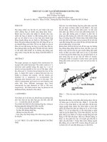
In figure 8.1 when oil supplied in port A, cylinder will develop force in forward direction.
Return stroke is achieved by gravity and spring. While in figure 1.2, when oil is supplied in port A,
cylinder will take forward power stroke and when oil is supplied in B-port, then cylinder will take
power stroke in reverse direction.
Chapter - 8
Introduction to Hydraulic Cylinder
8-1
B-Port of cylinder
A-Port of cylinder
Figure No. 8.1Spring Return Single Action Cylinder
“Design and Manufacturing of Hydraulic Presses.” ©: Q.S. Khan
Design and Manufacturing of Hydraulic Cylinder
1. Piston Rod: -
When diameter of piston rod is almost equal to piston diameter then generally it is called as RAM.
But in general all large size of piston rods are called "RAM". Piston rod is a mechanical member,
which transmits kinetic energy, which got developed at piston, to the work-piece. It is circular
in cross-section in case of double action cylinder, as hydraulic sealing is required between piston
rod and guide bush. In ram type of single action cylinder, piston rod is also circular in cross
action, while in piston type single action cylinder in which sealing is not required between piston
rod and guide bush, piston rod may be of any type of cross section. For example in case of lock nut
type of single action jack, piston rod has thread on its entire length. Piston-rod is also called as
plunger. It could extend from both the end of cylinder, and it could be hollow also. Piston-rod could
be attached to other component by means of threading, eye bolt type arrangement, or groove and
split coupling arrangement etc.
8-2
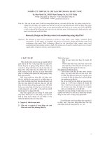
Figure No.8.2 Cross Section of a Doudle Action
Front Tube Flange Mounted Hydroulic Cylinder
SEAL PLATE
THROTTLE VALVE (FOR CUSHIONING)
STROKE OF CYLINDER (A)
OIL PORT FOR FORWARD
CHECK VALVE (FOR CUSHIONING)
ROD (FOR CUSHIONING)
TAPPER END OF PISTON
END PLUG
LOCK NUT
SEAL PLATE
PISTON SEAL
PISTON SEAL
PISTON
`O' RING
OIL PORT FOR RETURN
STROKE OF CYLINDER (B)
WELDED FRONT FLANGE
STOPPER TUBE
MAIN SHELL
BLEED OFF PORT
`O' RING
SLEEVE GUIDE / COLLAR GUIDE
ROD SEAL (GLAND SEAL)
GLAND BUSH
GUIDE BUSH
WIPER SEAL
PISTON ROD
Guide Ring
“Design and Manufacturing of Hydraulic Presses.” ©: Q.S. Khan
Design and Manufacturing of Hydraulic Cylinder
2. Wiper Seal: -
These are used to avoid entry of dust particle in cylinder. When these seal softly wipe the rod
then it is called wiper seal and when they are stiffly and forcefully rub the piston rod to avoid
entry of dust particle in cylinder then they are called “scraper”.
3. Gland-Bush: -
Gland-bush is used to retain gland seal, accommodate wiper seal, and provide guide to piston
rod. It is an optional component; it could be merged with Guide-bush. That means guide-bush
can also accommodate rod seal, wiper seal and can provide guide to piston rod. We provided
separate gland-bush for convenience in manufacturing, controlling dimension accurately, and
stronger design.
Making grove in Guide-bush and maintaining tolerance and surface finish is too difficult, so by
using gland bush we make an open step for accommodating seal and solve this problem.
Guide-bush is made from mild steel, while guiding piston rod requires bearing material. So
instead of making complete guide bush of bearing material we make gland-bush of bearing
material, Which is smaller in size as compared to guide-bush, and hence we save money.
Strips and bush could be used to provide guide to piston-rod in Guide bush, instead of making
separate gland bush. But long guides provided by gland-bush which are made from bearing
material are much stronger and gives long life as compared to thin and short bushes and strips
Filled in guide-bush.
4. Rod Seals: -
These are also called as Gland seals. It is a device which is used to avoid the leakage of working
fluid or air from the periphery of piston-rod, Generally it is used to stop leakage between piston
rod and guide-bush of cylinder.
5. Removable Guide Bush (Sleeve Guide): -
This is inserted in guide-bush before seals. This gives additional guide to Piston - Rod. It is also
called sleeve guide or collar guide.
6. Guide-Bush: -
It is also called as “Head End”, “Rod-end”, “front-end:, or “front-Face” (of cylinder). This is a
cylinder end enclosure, which covers the annular area or the differential area between the cylin-
der bore area and piston rod area.
In addition to functioning as end-closer, it also could be used for mounting cylinder, providing
oil-port, accommodating bleeding and cushion arrangement, and providing guide to piston rod.
7. Oil Port: - A port is an internal or external terminus of air or fluid passage in hydraulic
or pneumatic component.
In hydraulic cylinder, oil ports are provided to feed pressurised oil. It may be threaded or bolted
type, and its size depends on the flow of oil thought these oil ports and inside diameter of
cylinder
8. Cylinder-Tube-Flanges: -
These are circular or rectangular rings, threaded and welded to the outside diameter of cylinder
tube. When this is fixed at front-end of cylinder then it is called Front-Tube-Flange. It may be
used for bolting of guide-bush and cylinder mounting, in case of Front-Tube-Flange mounted
type of cylinder.
When it is fixed to the rear-end of cylinder (end-plug side), then it is called “Rear-Tube-Flange”
of cylinder. It may be used for bolting of End-Plug and cylinder mounting in case of Rear-Tube-
Flange mounted cylinder.
9. 'O' Ring:-
it is a ring with round cross-section, and used to stop leakage between mating components.
10. Stopper Tube: -
When cylinder has long stroke, and in fully extended condition of Piston-rod, if there is a chance
of buckling of piston-rod or any damage to cylinder, then piston-rod is always kept sufficiently
8-3
“Design and Manufacturing of Hydraulic Presses.” ©: Q.S. Khan
Design and Manufacturing of Hydraulic Cylinder
inside cylinder, so that the gland-bush and piston, which provide guide to piston-rod are sufficiently
apart from each other, and provide good cantilever support against bending and buckling.
A piece of pipe, which floats freely between piston and guide-bush, and stop ram from taking its
full stroke, is called stopper-tube.
11. Air-Bleed-Off-Port:-
Air may get trapped in cylinder. This air may be due to cavitations and de-aeration in oil, or air
present while assembling and commissioning of cylinder. Trapped air gives spongy operation, jerks,
and loss of control on cylinder movement. To remove trapped air small tapped holes are provided in
end-plug and guide-bush, which always remains plugged. To release air these plugs are loosened
allowing air to escape to atmospheres. When air is completely removed then oil started leaking-out
from these plugs, then plugs are tighten again.
This process of removing air till oil starts coming out is called bleeding and the port provided for
this purpose is called “air-bleed-off-port”.
12. Main Shell: -
It is also called “cylinder-tube”, or “cylinder-pipe”, or “cylinder-body”. It has circular inside cross-
sectional area. It receives, confines, and direct the fluid under pressure to piston or ram so that the
pressure energy in fluid gets converted into kinetic energy of the moving piston or ram. The cross-
section area of cylinder-tube withstands radial as well as longitudinal stress developed due to the
fluid-under-pressure. It also provides guide to ram or piston.
13. Seal Plates: -
These are round rings or plates, used to retain piston-seal on piston.
14. Piston Seal: -
These are hydraulic seals used to avoid leakage between piston and inside diameter of cylinder
tube.
15. Piston: -
Piston is circular in cross-section. It slides in main shell, and provides guide to piston rod at one-
end (piston-end). Piston has provision and means to avoid leakage between cylinder and piston,
and because of this feature, when fluid-under-pressure when enters in main shell in one direction,
piston gets pushing force in other direction. Hence it assists in conversion of pressure energy in
fluid to kinetic energy
16. Lock Nut:-
To avoid losing of piston from piston-rod these lock nuts are provided.
17. Guide-Ring: -
These are flat rings of plastomeric material. And used in piston, guide-bush, and gland-bush to
avoid metal to metal contact, and act as guide. All mechanical property of guide-rings are similar to
bearing material.
18. Cushioning:-
As per the requirement of hydraulic system, piston-rod may travel at extremely high speed in its
stroke range. On completing its stroke if piston hits guide-bush or end-plug with same high speed
then it will damage the whole cylinder. Hence special arrangements are made in piston and end-
covers to reduce the speed of piston-rod as it completes its stroke. This process of deceleration of
piston or piston-rod is called cushioning.
Cushioning is achieved by throttling the rate of exhaust or return of oil, from cylinder. Cushioning
may be fixed type or variable type; Detail about arrangement of cushioning will be discussed in
design of cylinder.
19. End-Plug: -
It is also called as “Cap-End” “Cover - End” or “Rear - End” (of cylinder) this is a cylinder-end
enclosure which completely cover the cylinder-bore-area. In addition to providing end enclosure,
end plug also could be used for mounting of cylinder, providing oil port, making arrangement for
bleeding, and cushion etc.
8-4
“Design and Manufacturing of Hydraulic Presses.” ©: Q.S. Khan
Design and Manufacturing of Hydraulic Cylinder
For more knowledge about terms used for hydraulic cylinder, and other items kindly refer
IS:10416:1982 which describes about 855 terms related to oil hydraulic.`
8-5
“Design and Manufacturing of Hydraulic Presses.” ©: Q.S. Khan
Design and Manufacturing of Hydraulic Cylinder
Basically there are only two types of hydraulic cylinder, namely single action cylinder and
double action cylinder. These two principal types of hydraulic cylinders have been modified in so
many ways as per requirement of industry, convenience in manufacturing, economy and duty
cycle. Some of them are described as follow.
8.1.1 Classification based on Body Construction of Hydraulic Cylinder: -
On construction basis hydraulic cylinders could be divided in to five categories.
1. Tie - Rod Construction.
2. Threaded Construction.
3. Bolted Construction.
4. One Piece welded construction.
5. Costume Build Cylinder with combination of above mentioned constructions.
8.2.2 Tie - Rod Construction: -
This type of construction is most widely used in industry. ISI standard also generally refers to one
of this type of construction. As all the components are only machined and assembled together and
not welded. Hence planning manufacturing, quality control, assembly, and maintenance are more
convenient than other types of construction. As long tie rods are used to hold all the component
together hence special care required to tighten them, and safe guard against loosening in operation.
Like standard valves and pumps, these types of cylinders are also manufactured as standard hy-
draulic component, and used for low to medium pressure and low to medium duty operation for
general purpose, and machine tool industry.
Classification of Hydraulic Cylinders
8-6
8.2 Classification of Hydraulic Cylinders
Tie Rods
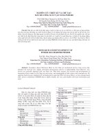
Figure No. 8.2.2
Tie - Rod Cylinder
Oil Port
Oil Port
Retaining Nuts
Shell
End-Puug
guide-Bush
Piston-rod
“Design and Manufacturing of Hydraulic Presses.” ©: Q.S. Khan
Design and Manufacturing of Hydraulic Cylinder
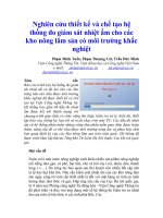
8.2.3 Threaded Construction: -
This construction is similar to tie-rod construction, but more compact, stronger, and re-
quires more accuracy and care in manufacturing and quality control. In this design both ends are
assembled with cylinder tube by threading, as shown in following design.
These are used for medium to heavy-duty operation, and widely used in earth moving machinery.
8.2.4 Bolted Construction: -
This type of construction involves welding of flanges to cylinder tube, and bolting of end
cover to the welded flange. Similar to tie rod construction these are also designed and manufac-
tured as standard hydraulic component and widely used in industry.
Classification of Hydraulic Cylinders
8-7
Figure No. 8.2.3
Threaded - Head Cylinder
Oil Port
Oil Port
Figure No. 8.2.4
Bolted Construction
“Design and Manufacturing of Hydraulic Presses.” ©: Q.S. Khan
Design and Manufacturing of Hydraulic Cylinder
8.2.5 One Piece - Welded Cylinder: -
Similar to shock - absorber, in this design the end covers and cylinder tube are welded together.
These are economical but cannot be repaired. There are used for low pressure; agriculture machin-
ery application.
8.2.6 Custom - Build Cylinder: -
In this type of cylinder, various type of construction are mixed together to suit the requirement. One
of the most widely used combination is welded cap-end cover, bolted head-end cover, with front
tube flange mounting.
In case of high capacity cylinder when it is steel cast or machined from solid steel forging, then end
cover and front flange may be integral part of cylinder tube. Cylinder with this type of construction
widely used in hydraulic press.
Classification of Hydraulic Cylinders
8-8
Figure No. 8.2.5
One Piece - Welded Cylinder
Figure No.8.2.6
Custom - build Cylinder
“Design and Manufacturing of Hydraulic Presses.” ©: Q.S. Khan
Design and Manufacturing of Hydraulic Cylinder
Classification of Hydraulic Cylinders
8-9
8.3 Classification based on operating features of Hydraulic cylinder
8.3.1 Single Action Cylinder: -
This is the simplest type of cylinder and used since introduction of water hydraulic. In this
type of cylinder, ram or piston-rod have such construction that their displacement in one direction
is by fluid force and in other direction by external force.
8.3.2 Double Action Cylinder: -
This type is most widely used cylinder in industry. In this type of design the stroke of piston
rod in forward as well as in reversed direction is due to fluid pressure, as shown in figure 2.2
8.3.3 Differential Cylinder: -
When cross-section area of Piston-rod (Ram) is half the cross - sectional area of cylinder
bore of double action cylinder, then such cylinders are called Differential Cylinder.
When differential cylinders are connected to regenerative hydraulic circuit then it gives
same (equal) forward and return speed.
Figure No. 8.3.1
Piston-Rcd/Ram
Wiper Seal
Rod Seal
Main Sheel
Oil Port
Figure No. 8.3.1
Gravity return single action cylinder
“Design and Manufacturing of Hydraulic Presses.” ©: Q.S. Khan
Design and Manufacturing of Hydraulic Cylinder
8.3.4 Double - End Rod Cylinder: -
In this type of cylinder piston rod extends from both the ends of cylinder. As annular area on
both ends are same, hence it moves with same speed in its forward and return stroke. Sometime
piston is made hollow to pass the work-piece or another machine element through it.
8.3.5 Telescopic Cylinder: -
This type of cylinder provides long stroke from short body. Total stroke length
may be as much as four to six times longer than collapsed length of the cylinder. Telescopic cylin-
ders are single as well as double action. The force out-put varies with stroke. We get maximum
force on first stage when full piston area is used, while minimum force at the end of stroke.
These types of cylinders are used in dumper-truck, hydraulic mobile crane, and
Classification of Hydraulic Cylinders
8-10
Figure No. 8.3.4
Figure No. 8.3.5
Telescopic Cylinder ( Single action )
Oil port
(With hollow ram)
Double - end rod cylinder
Oil port Oil port
“Design and Manufacturing of Hydraulic Presses.” ©: Q.S. Khan
Design and Manufacturing of Hydraulic Cylinder
8.3.6 Multi position Cylinder: -
These type of cylinders provide special motion by moving two or more pistons inside the
cylinders. For example, in three-position cylinder as shown in following diagram, on pressuriz-
ing the cap-end-oil port the cap-end piston-rod forces against the head- end-piston, and moves it
to some portion of its stroke (generally about half of its total travel).
By Pressurizing the middle oil port, oil pressure separates the head-end-piston from the
cap-end rod, and force the head-end-piston to full extension. Three-position cylinders are often
used to actuate multi position valves or to shift gears in machine tools.
8.3.7 Diaphragm Cylinder: -
Diaphragm cylinders are used in either hydraulic or pneumatic service for applications
that require low friction, no leakage across the piston, or extremely sensitive response to small
pressure variations. They are frequently used as pneumatic actuators in food and drug industries
because they require no lubrication and do not exhaust a contaminating oil dust. Spring- return
models shown in figure should not be pressurized in the reverse direction because reversals can
pleat the diaphragm and shorten its life. Double-acting actuators with twin diaphragm are avail-
able for application requires pressure in both directions.
Classification of Hydraulic Cylinders
8-11
Figure No. 8.3.6
Multyposition cylinder
Cap end
Oil Port
Middle Oil
Port
Head-end Oil port
Cap-end-piston
Head-end-piston
Figure No. 8.3.7
Spring
Piston rod
Diaphragm
Piston
Oil inlet
Diaphragm Cylinder
“Design and Manufacturing of Hydraulic Presses.” ©: Q.S. Khan
Design and Manufacturing of Hydraulic Cylinder
8.3.8 Rotating cylinder: -
Rotating cylinders impart linear motion to a rotating device. They are often used to actuate rotating
chucks on turret lathe.
In this type of cylinder, complete cylinder assembly may rotate along with mating components.
Special journals, thrust bearing etc. are used to guide piston-rod and to reduce friction while rotat-
ing. Fluid is supplied through special stationary distributor.
( like rotary joints )Generally relative rotary motion between cylinder and piston are avoided as
high pressure seal would then be subjected to both rotary and linear wear force. But with low RPM
they can have relative rotary motion.
Hydraulic rotating cylinder and hydraulic torque motor are two different units. Hydraulic rotating
cylinder only imparts liner motion to a rotating device. While torque motor impart rotary motion to
a device to be rotated.
8.3.9 SLOTTED CYLINDER (Rod less):-
In slotted cylinder, piston extends through a slot in the side of the cylinder. The slot is sealed with
a spring-steel strip that is threaded through the piston assembly. So far sloteded cylinders are avail-
able for pneumatic system but not hydraulic system.
Classification of Hydraulic Cylinders
8-12
Figure No. 8.3.9
Slotted Cylinder
Piston assemblySteel strip
member
Out put
Slot
Moulded
seal
Figure No.8.3.8
Rotating Cylinder
Fluid
Stationary
distributor
Rotating body
“Design and Manufacturing of Hydraulic Presses.” ©: Q.S. Khan
Design and Manufacturing of Hydraulic Cylinder
8.3.10 Compound Cylinder: -
Compound cylinder consists of a secondary cylinder inside the main primary cylinder to improve
the performance of main primary cylinder.
Cross - section of a simple of compound cylinder is shown in following figure. In this cylinder we
can have three forward speeds and pressing force.
1) We get Maximum speed and minimum force when pump is connected to only B port, and
A & C is connected to tank.
2) Medium speed and force is achieved when A is connected to pump and B & C is
connected to tank.
3) Minimum speed and maximum force is achieved by connecting A & B to pump and C to
tank.
4) Single speed return speed is achieved by connecting C to pump & A & B to tank.
8.3.11 Intensifier: -
This is a type of compound cylinder. Which is used to boost the pressure of working fluids. Inten-
sifier may be a part of hydraulic circuit, in which pump initially supplies hydraulic fluid at low to
medium pressure to carry out all the operation and function of a hydraulic system and when high
pressure required then with the help of medium pressure hydraulic fluid and intensifier, high pres-
sure is developed. (fig.___)
Now-a-days readily available and economical. Piston pump can develop up to 630 Bar. Some
sophisticated pump can also develop up to 1000 Bar. But when oil at 1500 Bar or 2000 bar pressure
is continuously required then such type of intensifier is used.
In following example using low pressure pump very high pressure oil can be supplied to cylinder
Classification of Hydraulic Cylinders
8-13
Figure No. 8.3.10
COMPOUND CYLINDER
Oil port(c)
Oil port(b)
Oil port(a)
“Design and Manufacturing of Hydraulic Presses.” ©: Q.S. Khan
Design and Manufacturing of Hydraulic Cylinder
E] Operation Principle: -
I) When direction control valve Actuated to (A) piston, oil from pump passes to return side of
cylinder. Spring of check valve No.(5) is so strong that it does not allow oil to enter forward port of
cylinder and upright (3) unless. Cylinder gets fully retracted.
II) After full retraction of cylinder , oil passes from check valve (5) and enters in upright (3), which
cause plunger (2) to retract.
III) In fully retracted condition of cylinder and plunger ( 2) system is ready for forward stroke
cylinder.
IV) When solenoid is activated to B-position. Oil from pump is directed to forward port of inten-
sifier cylinder. This cause plunger (2) to more down and transfer oil in upright (3) to port for
forward stroke of
V) If area of intensifier cylinder (1) in A1 and pump pressure is P1, Area of upright (3) is A2 , them
pressure P2 got developed in up-right will be By this simple method method very high pressure
could be developed by using simple low pressure
Classification of Hydraulic Cylinders
8-14
Figure No. 8.3.11
Intensifier
M
Double action cylinder
Check
Valve
Intensifier cylinder
Plunger
Upright
Direction control valve
Relif valve
1
2
3
4
5
6
A B
“Design and Manufacturing of Hydraulic Presses.” ©: Q.S. Khan
Design and Manufacturing of Hydraulic Cylinder
8.3.12 Hydro-Pneumatic Reciprocating Pump: -
This is also a type of compound cylinder, it consist of a double acting pneumatic cylinder and a
single action hydraulic cylinder with common piston rod. Pneumatic cylinder is completely
made from non-magnetic material such as aluminum, brass or non-magnetic stainless steel. Pis-
ton ring of pneumatic cylinder consists of an additional magnetic ring. Out side cylinder tube
two "Proximity switches" are provided at both ends of cylinder tube. When piston with magnetic
ring passes near the proximity switch, it actuate. Proximity switch closes the electrical circuit
and supply of current to the coil of pneumatic direction control valve to actuate it. Pneumatic
direction control valve is detention type, that is once it get energized it changes its position, and
even after its coil gets de-energised, it remain in same position, and do not changes its position,
unless other side of coil is energised to changes it's direction.
In operation, pressurized air is supplied to four-way-two-position pneumatic direction control,
which operates cylinder, as cylinder takes its stroke, and piston with magnetic ring moves across
the "Proximity switch" it temporarily energies coils of direction control valve for the reverse
direction of cylinder. As reverse stroke progress, even though direction control valve get de-
energized but do remain in same position due to its detention characteristic. When reverse stroke
reaches its end, piston passes through the other "Proximity switch", it get operated for a very
short period of time. But in that short period it energies coil of direction control valve for
forward stroke and again change the direction of cylinder. That is how it changes direction of
stroke and cylinder keep on reciprocating. This reciprocating pneumatic cylinder connected to a
single action type of hydraulic cylinder, with two-check valve, which on its retraction stroke
suck oil, and on its forward stroke deliver oil under pressure.
The simple system we have described is by using magnetic ring, Proximity switch and detention
type Direction control valve. Reciprocating pumps are also available which are with out Proxim-
ity switch, and use only special pneumatic direction control valve. In one such system, pneu-
matic cylinder has cushion like arrangement at its both end. When piston reaches the end of its
stroke the pressure of air trapped between piston and end-cover increases slightly more than
supplied air pressure. This extra pressure is used to change the direction of detention type direc-
tion control valve. In operation spool of direction control valve get equal air pressure at its both
end and remain in balance, but at the end of stroke increase in pressure of the air-trapped in
cushion chamber off balance it and changes its direction.
So on this principle cylinder keeps on reciprocating and keep on pump flanged at pressure as
reciprocating pump.
Classification of Hydraulic Cylinders
8-15
Figure No. 8.3.12
Intensifer Cylinder Assembly
Oil port
Oil port
Actuating Cylinder
Suction
Intensifer Cylinder
pressure fluid
Delivery of high
Check-valve
“Design and Manufacturing of Hydraulic Presses.” ©: Q.S. Khan
Design and Manufacturing of Hydraulic Cylinder
8.3.13 Bred Bury Speed Ram: -
This is also a type of compound cylinder, in which ram of secondary cylinder is a free-floating tube.
Refer figure.
Primary cylinder is similar to convention at double action cylinder, but with hollow ram. A tube
freely float in this hollow ram, and held freely at some distance from inlet oil port. Oil is injected
through a nozzle at high velocity in the tube. When oil come out from other end of tube inside
hollow ram at high velocity, as velocity decreases, pressure increases. This pressure forces tubes
out of hollow ram, and presses it firmly on the opening of nozzle. This allows all the oil injected by
nozzle to pass on to hollow ram and force it out at high speed. As ram take its stroke at high speed
the volume of cap end cylinder is filled by oil through a large size of pre-fill valve, to avoid cavita-
tions.
As main ram (hollow ram) reaches its full stroke, some arrangement is made to leak the pressurized
oil getting injected in hollow ram to main cap-end area of cylinder, to develop full pressure and
force. This may be achieved by providing a side hole in tube or making it taper at the end and
increase the clearance.
This cylinder gives very high speed with very small capacity pump and motor. Speed ram is devel-
oped by Mr. Farel bred bury, and m/s. Broughton Redman Engineering Ltd. Birmingham is
Licensees to manufacture these cylinder commercially.
8.3.14 Non - Rotating Cylinder: -
Cylinder, piston, piston-rod, guide-bush, gland-bush all these components have circular guide.
When piston and piston rod take their stroke more, they are free to rotate. Hence alongwith a
desired linear motion, there is also an undesired rotary motion of piston rod along its central axis.
When a cylinder is assembled in hydraulic press and piston - rod is coupled to moving platen, this
rotary motion gets arrested. But when cylinder is not assembled in hydraulic press, and is required
to perform independently in various operations such as marking, punching, indexing etc. and ro-
tary motion of piston-rod not desired then piston-rod is guided externally. But this additional and
external guide takes lots of space and is a costly affair.
Hence non-rotating type of cylinders has been developed. It is similar to conventional double
action cylinder with three piston rods. All the three piston rod are coupled to same piston, and
passes through guide-bush, gland-bush etc. While manufacturing such cylinders, too much pre-
caution has to be taken regarding quality control. But if made correctly then these are economical
and convenient to use, and give good performance.
Classification of Hydraulic Cylinders
8-16
Bred bury speed ram
Figure No. 8.3.13
Pre-filliag by
Carend oil-port
Floating tube
“Design and Manufacturing of Hydraulic Presses.” ©: Q.S. Khan
Design and Manufacturing of Hydraulic Cylinder
8.3.15 Hydro - Pneumatic Cylinder: -
These are very important type of cylinders used extensive in industry for such operations which
require high production, very short production cycle, They require small stroke of cylinder under
load, such as punching reverting, marking etc.
Hydro-pneumatic cylinder is a compound cylinder in which a pneumatic cylinder and hydraulic
cylinder are assembled together in a special way.
Following figure and description will explain it various component and operation.
1] System start with revetting plunger at retracted position, and valve in switch-off condi-
tion.
Classification of Hydraulic Cylinders
8-17
Figure No.8.3.14
Non - Rotating Cylinder
oil port
oil port
A
B
C
D
F
E
Air-chamber
for return strock
Air-chamber for
fastforward strock
H
G
check-valve for
free return strock
Seqvence
check-valve
Air-chamber
for increasing
pressure in oil
Oil reservoire
Oil chamber for
pressure intensification
A
B
Figure No.8.3.15
“Design and Manufacturing of Hydraulic Presses.” ©: Q.S. Khan
Design and Manufacturing of Hydraulic Cylinder
2] To start system solenoil valve is energies, which cause supply of air in chamber.( B )
which is air chamber for a forward stroke. In this energized condition of solenoil chamber ( E)
which is air chamber for increasing pressure in oil is also get connected to air - pressure line.
But due to sequence check-valve, air does not enter in this chamber up to a set pressure ( may
be 5 bar ). Because of this oil get sucked in chamber (C) from (D) which is oil reservoir cham-
ber. Spring (F) expand when oil is sucked from chamber (D) to chamber (C). This also creates
low pressure in chamber (E) and favorable condition for cracking sequence check-valve.
3] When reveting punch senses some resistance, air pressure increases and over come resis-
tance offered by sequence check valve, and pressurised air enter in chamber ( E ). This causes
plunger
( H ) to enter in chamber ( C ). As soon plunger ( H ) enter the opening of chamber ( C ), oil get
trapped in chamber ( C ) due to oil seal and fine clearance. When air pressure further increases in
chamber ( E ) it exert more force on plunger ( H ). This causes increase in pressure in oil in chamber
(C).
Classification of Hydraulic Cylinders
8-18
Figure No. 8.3.17
Figure No. 8.3.16
H
B
C
D
F
B
Check valve for
free return stroke
Check valve for
free return stroke
“Design and Manufacturing of Hydraulic Presses.” ©: Q.S. Khan
Design and Manufacturing of Hydraulic Cylinder
4] As soon as reveting get completed, solenoil valve get de-energized, which connect cham-
ber ( B ) and ( E ) to atmosphere, and chamber ( A ) to compress pressure. This causes plunger ( G
) and ( H ) to retract under pressure of air and oil and transfer of oil from chamber ( C ) to ( D ).
8.3.16 Duplex Cylinder: -
These are two standard double action cylinder with independent direction control valve. These
cylinder are mechanically connected to each other with a common central axis. By this arrangement
we get number of piston-rod position depending on application.
8.3.17 Tendum Cylinder: -
In case of tendum cylinders we have two or more cylinders with inter connected piston assemblies.
8.3.18 Adjustable Stroke Cylinder: -
In this type of cylinder we have external mechanical arrangement, such as thread and lock-nut etc.,
to adjust and stop travel of piston-rod at desirable position.
Classification of Hydraulic Cylinders
8-19
Figure No. 8.3.18
Check valve for
free return stroke
B
“Design and Manufacturing of Hydraulic Presses.” ©: Q.S. Khan
Design and Manufacturing of Hydraulic Cylinder
8.4 Design of a Hydraulic Cylinder
8.4.1 Importance of safe design: -
Hydraulic cylinder is actuated by hydraulic fluid at very high pressure. Any failure of cylinder may
cause an explosion or ejection of a high velocity jet of oil, which may cause extensive damage to
property and fatal injury to human being. Hence most precaution should be taken while designing a
hydraulic cylinder. Author knows and has seen many accidents, which has cause lose of life,
He has described few accidents in chapter of “accidents by hydraulic system”. Hence study thor-
oughly the theoretical and practical aspect of design and then manufacture hydraulic cylinder.
8.4.2 Design of Cylinder Tube: -
In designing cylinder tube, we basically calculate it's inside diameter and wall thickness. Inside
diameter and wall thickness depends upon capacity of cylinder and working pressure. In following
paragraphs we will study how to determine these parameters.
8.4.3 Capacity of Hydraulic Cylinder:-
Capacity of a hydraulic cylinder is decided by the purpose for which cylinder is going to be used.
For example, if a cylinder is to be designed for deep drawing press to draw a particular utensil.
Then the capacity of cylinder will depend upon the size of utensil and thickness and mechanical
property of material to be drawn.
Hence before designing a cylinder it's capacity is determined, considering the operation it has to
perform.
8.4.4 Working Pressure: -
Working pressure of a system can vary from minimum possible to 700 Bar or more. It is selected on
two factors.
1. Size Constraint of cylinder
2. Type of valves and pump to be used in system.
1] Size Constraint of cylinder
a) Rubber molding presses are generally up-stroke presses, with larger presses table mounted
directly on piston rod. To support press-table firmly piston-rod should be of sufficiently large diam-
eter. For large piston-rod diameter, cylinder Inside Diameter should be more. Keeping same press-
ing capacity if Inside Diameter of cylinder has to be increased then pressure has to be reduced.
So to support large size of table, working pressure of system reduced.
b) Jacks are used for lifting various vehicles and equipment. Generally they are lifted and
placed in position by hand. For convenience in handling the weight of jack should be low. To
reduce weight the size of jack is reduced. For keeping same lifting capacity and to reduce size,
working presses of jack is increased to as high as 700 Bar.
Hence in this case working pressure increased to reduce the size of cylinder.
Similarly in most of the cases the space and size restriction in equipment where cylinder has to be
fitted, influence the selection of working pressure.
If there is no restriction on size of cylinder, then pressure is decided by type of hydraulic valves and
pump to be used in system. Type of valve and pump to be used is decided by.
a) Monetary budget.
b) Automation of system.
c) Type of equipment.
When budget is too low for manufacturing a hydraulic system, then gear or vane pump is used.
These pumps give optimum performance and continue pressure below 175 Bar. Hence for such
pumps, system pressure is kept 175 bar or less then that.
For common budget when piston pump is to be used then pressure could be kept up to 350Bar.
When system is to be used along with control panel. Then solenoid operated direction control
Design of Hydraulic Cylinders
8-20
“Design and Manufacturing of Hydraulic Presses.” ©: Q.S. Khan
Design and Manufacturing of Hydraulic Cylinder
valves has to be used. Such valves are designed for 315 Bar to 350 Bar. But they give optimum
performance below 300 Bar. Hence when solenoid operated direction control valve is to be used
then pressure is selected bellow 300 Bar.
For system like jacks, where size is to be kept minimum. And there is no automation, then using
piston pump or hand pump, pressure as high as 700 Bar can be achieved, and selected.
Hence before designing a cylinder-tube we decide two factors i.e. capacity and working pressure.
And once these two are decided then using various theories and formulas we can calculate inside
diameter of cylinder and wall thickness.
First we will discuss various theories and formulas for theoretically calculating the required dimen-
sion of cylinder tube. Then we will discuss the practical part of it. That is how to manipulate the
theoretically calculated size so that practically it is possible, feasible and economical to manufac-
ture the hydraulic cylinder tube.
8.4.5 Theoretical Design of Main Shell OR Cylinder Tube: -
Cylinder tubes are divided in to two categories.
1) Thin Cylinder Tube
2) Thick Cylinder Tube
For simplicity we will call cylinder tube as cylinder only in this chapter. When ratio of cylinder bore
to wall thickness is more than 10 then it is called thin cylinder. And when it is equal to or less than
10 then it is called thick cylinder. Equations to calculate wall thickness, and assumption made to
used them are different, hence we will discuses them individually as follow.
8.4.6 Design Of Thin Cylinder: -
The analysis of stress induced in thin cylinder is made on the following assumptions
The effect of curvature of the cylinder wall is neglected.
The tensile stresses are uniformly distributed over the section of the walls.
The effect of the restraining action of
the heads at the end of the cylinder tube is neglected.
Whenever a cylinder is subjected to an internal pressure, it is likely to fail either by splitting up into
two cylinders (splitting circumferentially) or splitting it up into two troughs (splitting longitudi-
nally). As shown in figures. No.
Hence the wall of thin cylinder when subjected to internal pressure has to withstand following two
types of tensile stress.
8-21
Design of Hydraulic Cylinders
“Design and Manufacturing of Hydraulic Presses.” ©: Q.S. Khan
Design and Manufacturing of Hydraulic Cylinder
When P = Intensity of Pressure ( Kg/cm² )
d = Inside diameter of shell ( cm )
t = Thickness of shell ( cm )
ft = permissible Tensile stress in shell material ( Kg/cm² )
8-22
a) Circumferential or hoop tress.
b) Longitudinal stress.
a) Circumferential or hoop tress:
Consider thin cylinder subjected to
internal pressure. Tensile stress
acting in a direction tangential to the
circumference is called circumferen-
tial stress or hoop stress. It is a
tensile stress in longitudinal section.
And expressed as
P = Intensity of Pressure (Kg/cm²)
d = Inside diameter of cylinder (cm)
t = Thickness of cylinder(cm)
ft = Circumferential stress or hoop
stress
in the cylinder (Kg/cm²)
In a closed vessel, tensile stress acting in the direction of the axis is the called longitudinal
stress. It is stress acting on the circumferential section CD as shown in following figure.
8.4.5 Thin Spherical Shells: -
Sometime the end cover of casted cylinder is in spherical shape. When thin spherical
shell subjected internal pressure tensile stress get developed in its wall, the thickness is calcu-
lated by following equation.
Longitudinal Stress (ft ) could be expressed as = f
f =
t
d
P
t
f
Figure No.8.4.1
t
f
L
t
p
Section CD
Figure No. 8.4.2
D
p
p
p
d
C
t
“Design and Manufacturing of Hydraulic Presses.” ©: Q.S. Khan
Design and Manufacturing of Hydraulic Cylinder
8.4.8 Design Of Thick Cylinder: -
In case of thin cylinder, stress assumed to be uniformly distributed over the section of wall, but in
case of thick cylinder same assumption cannot be made. In case of thick cylinder stress distribu-
tion are as follow.
Maximum radial stresses are generally equal to the internal pressure, and it is maximum
at inner surface of cylinder.
fr (max) = -p.
For calculating tangential stress following four equations are used.
1) Lame's equation: -
Lame's equation is used for designing cylinder of brittle material and it depends on maxi-
mum-stress theory of failure, and could be used for open as well as closed cylinder.
2) Brinie's equation: -
Brinie's equation depends upon the maximum strain theory of failure. That is failure will occur
when the strain reaches a limiting value. According to this theory the wall thickness of cylinder is.
This equation is generally used for open-end cylinder made of ductile material, such as
gun-barrels.
P
P
=
t
i
d
2
-
t
f
f
(
+
t
-1
(
=
ft(max)
i
P ( d ² + d ² )
0
i
( d ² d ² )0
=
2
f
+
(
t
[
t
i
d
f
(
+
t
1 P)+
]
-1
1 - )P
8-23
Design of Hydraulic Cylinders
Tensile stress
o
d
i
d
t
i
d
f
t
d
Figure No. 8.3.3
d
o
i
t
Radial stress
f
r
d
o
t