Proceedings VCM 2012 62 nghiên cứu thiết kế và chế tạo con quay vi cơ fork tuning
Bạn đang xem bản rút gọn của tài liệu. Xem và tải ngay bản đầy đủ của tài liệu tại đây (1.04 MB, 6 trang )
Tuyển tập công trình Hội nghị Cơ điện tử toàn quốc lần thứ 6 459
Mã bài: 108
Nghiên cứu thiết kế và chế tạo con quay vi cơ fork tuning
có độ nhạy cao
Design and Fabrication of an Enhanced Sensitivity Tuning Fork
Micro-Gyroscope
Nguyen Quang Long
1
, Chu Manh Hoang
1,
, Trinh Quang Thong
2
,
Chu Duc Trinh
3
and Vu Ngoc Hung
1
1
International Training Institute for Materials Science, Hanoi University of Science and Technology
2
The Institute of Engineering Physics, Hanoi University of Science and Technology
3
MEMS Dept., Faculty of Electronics and Telecommunications, University of Engineering and Technology,
Vietnam National University
e-Mail:
Tóm tắt:
Chúng tôi trình bày kết quả nghiên cứu thiết kế và chế tạo cảm biến con quay vi cơ fork tuning có độ nhạy
cao. Độ nhạy vận tốc góc của cảm biến được khuếch đại bởi hệ số phẩm chất của mốt nhạy khi điều kiện cộng
hưởng cơ trong mốt nhạy và mốt chấp hành được thỏa mãn. Cấu trúc điện cực răng lược trong mốt nhạy cũng
được cải tiến để tăng cường độ nhạy của cảm biến. Các thông số thiết kế của con quay vi cơ thỏa mãn điều
kiện cộng hưởng cơ của mốt nhạy và mốt chấp hành đã đạt được từ phân tích phần tử hữu hạn. Con quay vi cơ
đã đươc chế tạo bằng công nghệ vi cơ khối tỷ lệ cạnh cao trên phiến SOI. Tần số cộng hưởng của mốt nhạy và
mốt chấp hành của cảm biến chế tạo đo được là 11125 Hz và 11250 Hz. Kết quả này phù hợp với kết quả phân
tich phần tử hữu hạn. Hệ số phẩm chất của mốt nhạy và mốt chấp hành được xác định bẳng thực nghiệm trong
môi trường không khí là 44,5 và 140.
Abstract:
We report design and fabrication of an enhanced sensitivity tuning fork micro-gyroscope. The angular rate
sensitivity of the gyroscope is amplified by the mechanical quality factor of the sense resonant mode when the
resonant frequencies of the driving and sensing modes are closely matched. Added comb electrodes in the
parallel-plate sensing comb structure were also designed for enhancing the sensitivity of the sensor. From
finite element analysis, the design parameters for a gyroscope structure having closely matched resonant
frequencies were obtained. The gyroscope was fabricated by SOI-based high-aspect ratio micromachining
process. The drive and sense mode resonant frequencies of the fabricated device were experimentally
measured to be 11250 Hz and 11125 Hz, respectively, which are in good agreement with the designed
prediction by FEA. The measured quality factors of driving and sensing modes in air are 140 and 44.5,
respectively.
1. Introduction
Micromachined vibratory gyroscope is a key
element for applications in space navigation,
automobile and consumer electronics [1].
Recently, micromachined capacitive type tuning
fork gyroscopes has attracted a great deal of
attention due to their advantages such as low cost,
small size, low power consumption using
capacitance sensing mechanism. In addition, the
feature structure design of tuning fork is
considered to be insensitive to vibration and
possible to reject common-mode acceleration
inputs by a differential Coriolis measurement [2].
However, the detection of the sensor signal in
micromachined gyroscopes is quite challenging
due to small output capacitance signal. In order to
improve the sensitivity of a vibratory gyroscope,
the driving and sensing vibration modes of the
gyroscope need designed and fabricated with the
matched resonant frequencies [3]. When driven at
the resonant condition, the amplitude of sensing
mode vibration is amplified by its mechanical
quality factor. In [4], the sensing-mode quality
factor is increased by eliminating the energy
dissipation through the substrate using the anti-
phase operation of a dual mass tuning fork
gyroscope architecture and the mode-matching
operation in vacuum condition. In a latest report
[5], the research showed that the tuning fork
gyroscopes having decoupled sense and drive
masses with an anchored drive mass is less
460 Nguyen Quang Long, Chu Manh Hoang, Trinh Quang Thong, Chu Duc Trinh, Vu Ngoc Hung
VCM2012
sensitive to vibration than tuning fork gyroscope
designs featured in literature. To increase signal to
noise ratio, the mass and capacitance of a
capacitive type gyroscope are also required to be
as large as possible.
In this paper, design and fabrication of a
symmetric tuning fork gyroscope are reported. The
driving and sensing vibration modes of the
gyroscope are designed and fabricated with the
closely matched resonant frequencies for
enhancing the sensitivity. Added comb electrodes
in the parallel-plate sensing comb structure were
also designed for enhancing the sensitivity of the
sensor. The design parameters for a gyroscope
structure having closely matched resonant
frequencies were obtained by finite element
analysis. The gyroscope was fabricated by SOI-
based high-aspect ratio micromachining process.
The operation characteristics of the fabricated
device were investigated by designed electronic
interface circuit.
2. Design
The design of micromachined turning fork
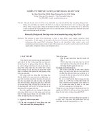
gyroscope is showed in Fig. 1 with the lateral
dimension of 4500 μm x 4350 μm. The thickness
of the structure is 30μm. The device would be
fabricated by one-mask process using Silicon On
Insulator (SOI) wafer.
Fig. 1 Schematic of micromachined Tuning Fork
gyroscope: (1) outer mass frame, (2) inner mass
frame, (3) drive comb electrodes, (4) sense
electrodes, (5) folded beam, (6) anchor, (7) lozenge
coupling spring, and (8) self-rotation ring
The main structure of the Turning Fork Gyroscope
design comprises two proof masses, each of which
includes the outer frame for driving and the inner
one for sensing. The drive comb electrode set is
attached to the outer frame and designed such that
in driving mode the masses oscillate in opposite
direction along x-axis due to electrostatics force.
The rotation rate is measured by a capacitance
change. A pair of sense electrode set using the
balanced scheme is placed symmetrically within
each inner mass frame. In order to increase the
change of capacitance, we here design four comb
banks each side of sense electrode set. The
dimension of comb finger is 30 μm length and 3
μm width. The gap between two adjacent fingers is
2.5 μm. Upon the rotation the Coriolis force
excites these mass frames in out of plane motion
that the differential capacitance can be detected.
This design also employs the folded beams for
suspension. The suspensions of the proof mass are
designed to allow the structure to oscillate in two
orthogonal modes.
After we have the designed model, the sensor was
verified by finite element analysis (FEA) using
ANSYS software. In this case, SOLID45 element
was employed for modeling and simulation. The
dimension parameters of the proof mass and the
suspension beam were investigated to have the
optimal the designed mechanical structure of the
gyroscope because vibration modes are strongly
dependent on these parameters.
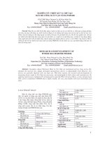
Figure 2 shows the FEA result of gyroscope for
sensing and driving modes. The resonant
frequencies of sensing and driving modes are
determined as 10,038 kHz and 9,918 kHz,
respectively. In fact, when the two modes are
matched, the output signal is amplified by the
quality factor of the sense mode, thereby
increasing the sense displacements by orders of
magnitude. Then, the amplitude along sensing
direction achieves the maximum. However, it
leads to a problem that the response time would be
long. The response of the gyroscope to time
varying rotation rate gives an indication of the
bandwidth of the sensor. The larger the bandwidth,
the quicker is the response of the sensor. That is
why there must be the difference between these
frequencies causing a width of the range of
frequencies. For Turning Fork Gyroscope, the
larger bandwidth is attained at the cost of
sensitivity. In this case, the drive and sense mode
frequencies have a mismatch of about 100 Hz
corresponding to the sensor bandwidth. This result
satisfies the requirement to optimize sensibility
and bandwidth. Using SIMULINK model, the
sensitivity of sensor was determined to be 11
fF/deg/s. To increase further the sensitivity, the
natural frequencies of the sensor structure need
decreased.
Tuyển tập công trình Hội nghị Cơ điện tử toàn quốc lần thứ 6 461
Mã bài: 108
Fig. 2 FEA result of gyros obtained by ANSYS, (a)
sensing and (b) driving mode
3. Fabrication process
The gyroscope has been fabricated by SOI-based
MEMS technology as shown schematically in Fig.
3. The main steps in the fabrication process are
described as follows. The 4-inches Silicon-On-
Insulator (SOI) wafer was used for fabrication
with thickness of a device layer is 30 µm, buried
silicon dioxide layer is 4 µm and substrate is about
500 µm (Fig. 3 (a)). First, the SOI wafer has been
cleaned by SC process. Next, the sensors patterns
were transferred to the surface of SOI wafer after
photolithography and developing processes (Fig. 3
(b)) with positive photoresist layer. This layer has
a role as protecting mask, which used for DRIE
process in next step.
Fig. 3 Main steps of the fabrication process
Then, DRIE process was performed to a depth of
30 µm to reach the buried dioxide layer of SOI
wafer (Fig. 3 (c)). The SOI wafer was then diced
to separate each sensor. Vapor HF etching process
was done to etch the SiO
2
underneath the device
layer and release the movable electrodes and
beams (Fig. 3 (d)).
4. Results and discussion
The fabrication of gyroscope have been
successfully performed by using only one photo
mask and standard MEMS processes such as
photolithography, DRIE processes and vapor HF
etching. The 4-inches SOI wafer with device layer
of 30 µm and buried SiO
2
layer of 4 µm has been
used to fabricate hundreds of sensors. After
fabrication, these sensors are ready for testing of
performances. The fabricated gyroscope is
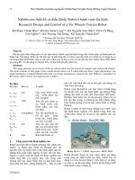
characterized by SEM.
Fig. 4 SEM pictures of fabricated sensor: top view
of whole structure (a), holes for releasing
structure (b) and zoom-in comb-fingers (c)
(a)
(b)
462 Nguyen Quang Long, Chu Manh Hoang, Trinh Quang Thong, Chu Duc Trinh, Vu Ngoc Hung
VCM2012
Figure 4 shows SEM pictures of gyroscope after
fabrication process. The pictures show that the
good fabrication process has been achieved. All
the moving parts seem to be released. The edges
are very well etched and not broken or damaged in
structure and sensing electrodes.
Packaging is a final step to complete the fabricated
sensors. Firstly, the sensor chip is glued on a
device holder using two components epoxy, which
may be either made of hard plastic or metal with
pins for use. Next step is wire bonding process. In
this work, the Westbond 7400C was used to
package the device.
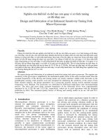
Figure 5 shows a picture of packaged device.
When the fabrication period is finished, basic tests
are performed on capacitive micromachined
sensors.
Fig. 5 Sensor after packaging
Fig. 6 The 1-port actuation and detection scheme
for frequency response extraction
These are the stiction test, short circuit test, and
capacitance test. These basic tests were carried out
using probe station equiped a microscope, a
milimeter and an impedance analyzer.
In order to improve the sensitivity of a vibratory
gyroscope, the driving and sensing vibration
modes of the gyroscope need fabricated with the
closely matched resonant frequencies. To
characterize frequency response of the driving and
sensing modes, the sensor is driven with a varying
frequency AC signal from one end of the drive or
sense electrode and then the output is taken from
the other end of the electrode. Figure 6 is
schematic diagram of frequency response
extraction circuit. The magnitude and the phase of
the output shows the magnitude and phase
response of the system. From this data, we can see
that the peak value of the magnitude response,
which corresponds to the resonance frequency of
the sensor.
A problem existing in this test is that the output
signal is naturally small. So, an amplifier
configuration is used in output end to amplify the
signal. In this test, the OP37 IC chip was used.
Beside the output signal is small, another problem
is that it is very hard to control both DC and AC
applied voltage, so the circuit to control
magnitude, frequency of AC and DC voltage
applied on sensor have also been built.
Fig. 7 Frequency response of driving mode
Fig. 8 Frequency response of sensing mode
The measured quality factors of driving and
sensing are 140 and 44.5, respectively.
5. Conclusion
Design and fabrication of a symmetric tuning fork
gyroscope with enhanced sensitivity were
presented. The closely matched resonant
Tuyển tập công trình Hội nghị Cơ điện tử toàn quốc lần thứ 6 463
Mã bài: 108
frequencies were obtained for the driving and
sensing vibration modes of the gyroscope. In order
to enhance the sensitivity of the gyroscope,
parallel-plate sensing comb structure with
increasing number of comb electrodes was also
designed. The gyroscope was fabricated by SOI-
based high-aspect ratio micromachining process.
Acknowledgement
This work is supported by the Ministry of Science
and Technology (MOST), Vietnam under the
NAFOSTED project coded MS 103.02-2010.23.
References
[1] Yazdi, N.; Ayazi, F.; Najafi, K.;
Micromechanical inertial sensors, in :
Proceedings of the IEEE, pp. 1640-1659, 1998
[2] Weinberg, M.S.; Kourepenis, A.; Error sources
in in-plane silicon tuning-fork MEMS
gyroscopes, J. Microelectromech. Syst. 15 (3),
pp. 479-491, 2006
[3] Maenaka, K., Fujita, T.; Konish, Y.; Maeda;
M.; Analysis of hightly sensitive silicon
gyroscope with cantilever beam as vibratin,g
mass, Sen. Actuators A, 54, pp. 568-573, 1996
[4] Trusov, A.A.; Schofied A.R.; Shkel, A.M.;
Study of substrate energy dissipation
mechanism in in-phase and anti-phase
micromachined vibratory gyroscopes, in: Proc.
IEEE sensors, pp. 168-171, 2008
[5] Yoon, S.W.; Lee, S.; Najafi, K.; Vibration-
induced errors in MEMS tuning fork
gyroscopes, , Sen. Actuators A, 180, pp. 32-44,
2012
Long Quang Nguyen received the
Diploma Engineer degree in
material engineering from Hanoi
University of Science and
Technology (HUST) in 2010.
Since 2009, he has been working
as a research assistant at International Training
Institute for Materials Science (ITIMS) in the field
of micromechanical systems. His current interests
are design and development of MEMS mechanical
sensor.
Chu Manh Hoang received the
M.Sc. degree in materials science
from the International Training
Institute for Materials Science,
Hanoi University of Science and
Technology, Hanoi, Vietnam, in
2007 and the Dr. Eng. degree from the Graduate
School of Mechanical Engineering, Tohoku
University, Japan, in 2011. He was a Fellow of the
Japanese Society for the Promotion of Science
from April 2010 to March 2012.
Since September 2012, Dr. Chu is a lecturer at
Hanoi University of Science and Technology. His
current research interests are MEMS inertial
sensors, micro-mirrors, and nanophotonic. He is a
reviewer for several international journals.
Thong Quang Trinh received his
PhD degree in electrical
engineering from Dresden
University of Technology,
Germany, in 2006. From 1986 to
1999 he worked in the field of
applied physics at the Institute for
Applied Physics at Vietnamese Academy of
Science and Technology (VAST). Since 2000 he
has been Senior Scientist at Hanoi University of
Science and Technology (HUST). His current
research interests are focused on the design of
sensors and sensor systems including the
simulation of their components as well as
development of MEMS mechanical sensors for
different applications.
Chu Duc Trinh received the B.S.
degree in physics from Hanoi
University of Science, Hanoi,
Vietnam, in 1998, the M.Sc.
degree in electrical engineering
from Vietnam National
University, Hanoi, in 2002, and
the Ph.D. degree from Delft University of
Technology, Delft, The Netherlands, in 2007. His
doctoral research concerned piezoresistive sensors,
polymeric actuators, sensing microgrippers for
microparticle handling, and microsystems
technology.
He is currently an Associate Professor with the
Faculty of Electronics and Telecommunications,
University of Engineering and Technology,
Vietnam National University, Hanoi, Vietnam.
Since 2008, he has been the Vice-Dean of the
Faculty of Electronics and Telecommunications.
He has been chair of Microelectromechanical
Systems and Microsystems Department, since
2011. He has authored or coauthored more than 50
journal and conference papers.
He was the recipient of the Vietnam National
University, Hanoi, Vietnam Young Scientific
464 Nguyen Quang Long, Chu Manh Hoang, Trinh Quang Thong, Chu Duc Trinh, Vu Ngoc Hung
VCM2012
Award in 2010, the 20th anniversary of DIMES,
Delft University of Technology, The Netherlands
Best Poster Award in 2007 and the 17th European
Workshop on Micromechanics Best Poster Award
in 2006. He is guest editor of the Special Issue of
“Microelectromechanical systems” Vietnam
journal of Mechanics, in 2012.
Hung Ngoc Vu received the B.S. degree in physics
from Kishinev University (USSR), in 1979 and the
Ph.D. degree from Hanoi
University of Technology
(Vietnam), in 1991. His doctoral
thesis dealt with the
xeroradiography. At present, he is
an Associate Professor with the
International Training Institute for
Materials Science (ITIMS), Hanoi
University of Technology. His current research
interests are in the area of MEMS inertial sensors
and PiezoMEMS.