Proceedings VCM 2012 101 đề xuất bộ điều khiển thích nghi nhiệt độ cho thiết bị HVAC để quản lý
Bạn đang xem bản rút gọn của tài liệu. Xem và tải ngay bản đầy đủ của tài liệu tại đây (761.2 KB, 8 trang )
Tuyển tập công trình Hội nghị Cơ điện tử toàn quốc lần thứ 6 739
Mã bài: 160
Development of an adaptive temperature control for HVAC to
intelligent energy management system in buildings at DaNang city
Đề xuất bộ điều khiển thích nghi nhiệt độ cho thiết bị HVAC để quản lý
thông minh hệ thống năng lượng trong các tòa nhà tại TP Đà Nẵng
N. M. Tri
1
, N. H. Anh
2
, T. Q. Tuan
3
, H.D. Hoan
2
, N.D.H.Phuong
4
1
Vietnam Electricity-EVN
2
QuyNhon University, Vietnam
;
3
IDEA, Grenoble-INPG, France
Senior Member, IEEE
Abstract:
In order to use loads in an active and intelligent way to resolve technical problems in the networks or
contribute to ancillary services (smart grid), this paper presents a new method of air-conditioning control that
allows to reduce the peak consumption by maintaining thermal comforts. This control is based on the variable
set-point temperature of air conditioning adapted to the permissible power. This power can be fixed by outdoor
signal from DNO (Distribution Network Operators). In addition, this method relies support on a wireless
sensor network (WNS) which allows to measure in realtime simultaneously the internal temperatures and the
power consumption. The protocol Zigbee is used for the communication between wireless temperature sensors.
The proposed air-conditioning control is tested by simulation under EMTP-RV with satisfied results for a
distribution network containing air-conditioners at DaNang. These results show that the proposed solution can
be efficiently applied for a group of loads, buildings (such as a virtual consumer) in distribution networks in
order to reduce the peak consumption in the distribution network.
Keywords— Air conditioning, direct load control, adaptive control, peak load reduction, distribution
network, Zigbee, wireless sensor network, WNS.
Toám tắt:
Để giải quyết các vấn đề về kỹ thuật, dịch vụ trên lưới điện cần có phương pháp điều chỉnh nhu cầu sử
dụng tải một cách chủ động và linh hoạt, bài viết này trình bày một phương pháp mới để điều khiển thiết bị
điều hòa không khí; cho phép giảm tiêu thụ cao điểm mà vẫn duy trì các tiện nghi về nhiệt. Điều khiển này dựa
trên việc thiết lập nhiệt độ của điều hòa không khí thích ứng với công suất làm việc cho phép. Công suất này
có thể được cố định bởi tín hiệu bên ngoài(Nhà cung cấp và phân phối điện). Ngoài ra, phương pháp này có sự
hỗ trợ của một mạng cảm biến không dây (WNS) cho phép đo trong thời gian thực đồng thời nhiệt độ và công
suất tiêu thụ điện. Giao thức Zigbee cho phép giao tiếp giữa các cảm biến nhiệt độ không dây. Việc kiểm soát
bằng phương pháp đề xuất được thử nghiệm trên phần mêm EMTP-RV trên một mạng lưới phân phối có điều
hòa nhiệt độ tại Đà Nẵng. Những kết quả này cho thấy rằng các giải pháp được đề xuất có thể được áp dụng
quản lý hiệu quả cho một nhóm tải, các tòa nhà… để giảm công suất tiêu thụ trong giờ cao điểm hoặc khi điều
độ yêu cầu của lưới điện phân phối.
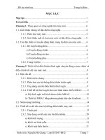
1. Introduction:
oad management is defined as sets of
objectives designed to control and modify the
patterns of demands of various consumers of a
power utility. Load management permits to limit
or shift peak load from on-peak to off-peak time
periods. Load management is dedicated to
control systems which monitor and plan the
energy demand of a building or larger zone.
They can be programmed to control lighting,
thermal comfort equipment, HVAC,
refrigeration equipment, pumps, valves and
motors (Fig. 1).
The sector of the building presents one of the
greatest potentials of energy efficiency and
reduction of the gas emissions. The use of the
loads in an active and intelligent way and
optimal load management is one of the major
L
740 N. M. Tri
, N. H. Anh, T. Q. Tuan
, H.D. Hoan
, N.D.H.Phuong
VCM2012
concerns of the managers, the providers and the
consumers of energy.
The peak consumption reduction is one of the
most effective solutions of energy management
systems. This reduction presents many interests:
For the customers: reduce the bill for the
subscription and consumption in peak hours,
For the DNO (Distribution Network
Operator): avoid the congestion and the
problems caused by overloads,
For the energy provider: limit the purchase
of an expensive energy.
In order to develop the intelligent electric
distribution networks in the future (Smart Grid),
direct load control for controllable loads plays
an important role. Loads become active and
intelligent. The loads participate to resolve
technical problems in the networks or contribute
to ancillary services such as voltage control,
congestion management…
The air-conditioning is a controllable load.
For tropical countries in summer, it takes an
important part in the tertiary and residential
buildings. Demand Side Management (DSM)
considers air-conditioning load as one of the
most suitable loads to implement direct
customer load control in order to exercise peak
demand control as well as energy consumption
control in supply systems [1-8]. In DSM, the air-
conditioning units located at customer premises
are directed to enter energy/demand saving
control modes by means of control signals
issued by DNO from sub stations either via
remote radio link or via power line carrier
communication link at distribution level when
the utility wants to exercise demand control
during periods of power shortage. Therefore the
management of air conditioners has an important
potential to reduce the peaks of consumption
and permits to contribute to ancillary services in
distribution.
Figure 1. Energy and load management system
In Vietnam, the electric power consumption
is always superior to the electric power
production. The load sheddings in on-peak
periods in order to avoid over load or blackouts
are inevitable. The air-conditioning takes an
important part in the tertiary and residential
buildings. This is why the direct load control of
air conditioning presents one of the best
solutions to reduce peak consumption.
In this paper, an adaptive control of air-
conditioning units is proposed. Then the
proposed solution is applied for a distribution
network in order to reduce the peak load
consumption and to avoid congestion.
2. Load control
2.1 Techniques of load control
Techniques of load control can be presented
in the following: Time- Of- Use-Tariff,
Interruptible Load Tariffs, Distribution System
Loss Reduction (ex: reactive compensation).
2.2 Measurement for load management
Load control can be realised for lighting load
and HVAC. Load control strategies can be
presented as following:
Fixed Priority Strategy
Priority strategy sheds the least important
loads first and the most important last. The last
load shed is the first to be restored.
Fixed Priority Strategy
Priority strategy sheds the least important
loads first and the most important last. The last
load shed is the first to be restored.
Rotate Strategy
The rotating sequence provides for an equal
distribution of power to all controlled loads.
Combination Fixed/Rotate Strategy
This is the most versatile and powerful
strategy because so many combinations are
possible.
Adaptive Control Strategy
This is an intelligent strategy by using an
adaptive control for variable set-point values.
3. Principle of the adaptive
control of air-conditioner
3.1. Model of air conditioner
The operation of an air conditioner is based
on the phase change of a fluid refrigerant:
evaporation occurs with heat absorption,
condensation with heat production. Therefore, in
any air conditioner there is:
Tuyển tập công trình Hội nghị Cơ điện tử toàn quốc lần thứ 6 741
Mã bài: 160
- An exchanger evaporator where cooling
associated with the evaporation of refrigerant is
transmitted to the ambient air;
- A compressor compressing the gaseous
fluids, increasing pressure and temperature;
- An exchanger condenser where gas
transfers its heat by condensing;
- A relief valve decreasing the pressure of the
liquid refrigerant before its evaporation in the
heat exchanger.
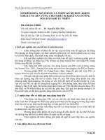
In this paper, the electrical analogue model
for an air conditioned house proposed in [7] is
used Fig. 2 shows the model of an air
conditioning developed with EMTP-RV. From
this model, we propose a new method based on
the adaptive control of air-conditioner for load
management system.
Iac S(t)
Is
Rw
Rw
C
w
Ci
To
R
c
To
Tw
Ti
Iinst
Figure 2. Electrical analogue model for an air
conditioned house
Where:
Rw, Cw: the equivalent thermal conduction
resistance and thermal storage capacity of
the house (wall, base, roof)
Rc, Ci: the equivalent thermal conduction
resistance of the average air infiltration and
thermal capacity of the air inside the house
To, Tw, Ti: the exterior temperature, the
wall temperature and interior temperature
Is : the current source of two components
(solar irradiation and the portion of internal
heat sources involved in this indirect heating
of air)
Iinst: the current source of heat source
produced by lamp, computer, the body…
Iac: The heat removed by the air
conditioner
S(t): The switching function (= 1 when the
compressor motor is ON and = 0 when the
compressor motor is OFF).
In Fig. 2, the equivalent thermal conduction
resistance of inside-wall and outside-wall (Rw)
are assumed to be equal.
The differential equation system is obtained
by applying Kirchoff’law at the nodes:
Where Tw and Ti are the unknown variables.
RwCw
Tw
RwCw
To
RwCw
Ti
Cw
Is
dt
dTw 2
(1)
RcRwCi
Ti
RwCi
Tw
RcCi
To
Ci
tIacS
Ci
Iinst
dt
dTi
11
)(
(2)
Where Tw and Ti are the unknown variables.
The Fig. 3 shows the EMTP-RV model of the
air conditioner that is built from this differential
equation system. In order to connect to
distribution network, the air conditioner is
modeled with EMTP-RV by a current injection.
f(u)1
Fm1
f(u)1
Fm12
f(u)1
Fm13
f(u)1
Fm14
+
+
+
+
+
sum6
f(u)1
Fm15
f(u)1
Fm16
f(u)1
Fm17
f(u)1
Fm18
f(u)1
Fm20
+
+
+
+
+
+
sum7
!h
Int3
!h
Int4
f(u)
1
2
3
Fm2 2
c
#P_AC#
C1
+
+
+
+
sum8
c
#T_Set#
C4
scope
T_int
c
C10
1
Ftb3
f(u)
Fm2 3
Ftb4
c
C11
0
scope
T_ext
scope
Sola r
f(u)1
Fm2 4
-1
Gain 1
scope
Q_AC
-1
Gain 2
scope
scp6
f(s)
fs1
f(u)1
Fm2 5
scope
P_AC
P_Depas
f(u)=0
1
2
Relay
Iinst
scope
F _ A C
Figure 3. Air conditioner modelized using
EMTP-RV
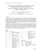
3.2. Proposed adaptive control
In general, a modern air conditioner is
equipped with a temperature regulator (called
classical control). This regulator is used to
maintain the temperature in a specified value
and carried out by a thermostat (a bimetal or an
electronic thermostat). The classical controls can
ensure the thermal comfort, but this method is
not able to vary the power consumption and can
also cause an excess from a permissible power
fixed by outdoor signal from DNO (Distribution
Network Operators).
In order to reduce the peak consumption for a
network in presence of air conditioners, this part
presents a development of an adaptive
temperature control for air conditioning.
In the normal operation (without excess of
contractual demand or without outdoor signal
from DNO or energy provider), the regulator
operates like a normal temperature regulator to
ensure thermal comfort (Ex: Tset-point ±1
where Tset-point is constant and fixed).
742 N. M. Tri
, N. H. Anh, T. Q. Tuan
, H.D. Hoan
, N.D.H.Phuong
VCM2012
Classical
regulator
Air
conditioning
M
eteorologies
Conditions
P_permissible
Temperature
regulator PID
and Fuzzy
-
T_room
P_total
Temperature
Set-point
Thermal model
of building
( surfaces, walls,
windows )
+
Adaptive module
+
-
Adaptive
conversion
ΔP ΔT
Figure 4. Principle of the proposed
air conditioning control
In case of excess of contractual demand or
with outdoor signal (ex: congestion signal
generated by DNO), the regulator switches to
the adaptive regulator mode with a variable set-
point value of temperature in order to limit the
peak of consumption to a predefined level. The
principle of the proposed air conditioning
regulator is represented in Fig.4.
In case of excess of contractual demand or
with outdoor signal, this signal converts it into a
temperature variation corresponding to required
reduction power. This value is transmitted to
each air conditioning in order to modify the set-
point temperature. In a distribution network with
different houses, the permissible power signal of
DNO is generated from sub stations.
4. Real-time control using Zigbee sensor
network for energy management system
in buildings
In the light of developments in microelectro-
mechanical systems (MEMS), along with
progress made in communication and embedded
smart sensors, the residential sector has a huge
potential for mitigating demand. The
possibilities of creating networks between home
appliances, sensors and wireless media, enable
the control of domestic equipment locally or
remotely via the Internet. The development of
WNS, with the Zigbee technology allows us to
establish more sophisticated control based on the
combination of measured information and
intelligent control in order to improve the use of
electrical equipments.
The advantages of this type of technology
ZigBee include:
Elimination of all costs related to the
physical connection of devices.
Possibility of establishing a single
communication interface between several
devices, using a communication protocol
supported by numerous manufacturers.
Ability to automatically reconfigure the
communication network each time a new
element is added.
This application relies on a wireless sensor
network (WNS) which allows simultaneous,
real-time measurement of indoor temperature
and power consumption. The ZigBee
communication protocol is used between
wireless temperature sensors and equipment.
Table 1. Electrical appliances of the
apartement
Name Description
air
conditioning
Traditional air conditioning
Actuator
Implements control actions
from the control unit
ZigBee
layers
ZigBee layers for
communication
This system comprises an array of wireless
temperature sensors, a wireless electrical power
sensor, radiators equipped adaptive controls, and
a central control unit (Fig.5).
Figure 5. Architecture of system
The Wireless Electrical Power Sensor
comprises two components: a power sensor and
a communication unit. The first component is
used to measure power consumption
instantaneously. The communication unit
transmits this information to the central cont rol
unit. The wireless electrical power sensor
receives the consum ption information and
detects excessive power (beyond the authorized
power limit).
air
conditioning
air
conditioning
Tuyển tập công trình Hội nghị Cơ điện tử toàn quốc lần thứ 6 743
Mã bài: 160
The central control unit : in our system, the
control unit is a computer equipped with a
wireless communication module and control
software. The central control unit analyzes the
information received. The central control unit
processes the temperature and power
measurements and makes decisions to control
the air conditionings in an intelligent manner,
maintaining comfort and keeping power
consumption below the authorized power limit.
The array of Wireless Temperature Sensors is
programmed to measure temperature within the
building at all times. After collection, this
information is transmitted to the central control
unit via a ZigBee communication link.
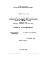
5. Application for a distribution network at
DaNang city
The proposed temperature control is used for
air conditioner load in a LV rural distribution
network at DaNang city as shown in Fig. 7. This
network is connected with a MV network via a
100 kVA, 22/0.4 kV transformer. This network
contains 12 air conditioners with 5kW for
individual houses. Other loads (lightning,
freezer, refrigerator, cooker, washing-
machine…) are considered as an equivalent load
in each house. Fig. 6 shows the daily variation
of these loads (active and reactive power). The
maximal active power is 5 kW. The power
factor of equivalent load is 0.93. The total
consumption of each house includes two parts:
consumption by air-conditioner and
consumption by this equivalent load.
The exterior temperature variation is
presented in Fig. 8. Total equivalent power
obtained from solar irradiation (Is) for each
house is showed by (Fig. 9). We suppose that
the load variation, the exterior temperature
variation and the solar irradiation are identical
for all houses in this network.
Figure 6. Daily variation of residential loads in
each house without air conditioners
+
1
R3
+
1
R1
LF
LF1
Slack: 20.5kVRMSLL/_0
Phase:0
+
5nF
C1
p1 p2
N1 N2
ALM 70_1 30m
PI
p1 p2
N1 N2
ALM 70_ 185m
PI
p1 p2
N1 N2
ALM 70_ 1000m
PI
p1 p2
N1 N2
ALM 70 _346m
PI
p1 p2
N1 N2
ALM 70_416
PI
p1 p2
N1 N2
ALM7 0_130m
PI
p1 p2
N1 N2
ALM7 0_251m
PI
p1 p2
N1 N2
ALM3 5_145m
PI
p1 p2
N1 N2
ALM 35 _157m
PI
p1 p2
N1 N2
ALM 35 _121m
PI
p1 p2
N1 N2
ALM 35_ 130m
PI
p1 p2
N1 N2
ALM 35_ 127m
PI
p1 p2
N1 N2
AL9 5_50S_470m
PI
1 2
DY_1
20/0.42
+
S_HTA
20.5kVRMSLL /_0
Slack:LF1
p
V_pu
V4
p
V_pu
V5
p
V_pu
V3
p
V_pu
V2
P
ic
p1
50Hz
Qic
p2
50Hz
L_AC
N
Load_AirConditi oning
L_AC_5
L_AC
N
Load_AirConditioning
L_AC_4
L_AC
N
Load_AirConditi oning
L_AC_3
L_AC
N
Load_AirConditi oning
L_AC_6
L_AC
N
Load_AirConditioning
L_AC_7
L_AC
N
Load_AirConditio ni ng
L_AC_14
L_AC
N
Load_AirConditio ni ng
L_AC_9
L_AC
N
Load_AirConditi oning
L_AC_10
L_AC
N
Load_AirConditioning
L_AC_12
L_AC
N
Load_AirConditioning
L_AC_13
L_AC
N
Load_AirConditioning
L_AC_11
L_AC
N
Load_AirConditi oning
L_AC_8
AAR
AAR
HTA
LV2
LV11
LV14
LV5
LV4
LV3
LV6
LV7
LV12
PV13
LV10
LV9
LV8
T_Red
Figure 7. Rural distribution network with air conditioners simulated with EMTP-RV
5.1 Classical temperature control
For this case, the set-point temperature of each
house is 20°C (±1°C) and all the air-conditioners
use the classical temperature control. The
permissible power is fixed to 100 kVA. This is the
rated power of the HV/LV transformer.
Fig. 10 shows the total power measured at the
transformer. It shows that there is a 10% overload
0 2 4 6 8 10 12 14 16 18 20 22 24
0
0.5
1
1.5
2
2.5
3
3.5
4
4.5
5
Times (H)
Power load (kW, kVAR )
744 N. M. Tri
, N. H. Anh, T. Q. Tuan
, H.D. Hoan
, N.D.H.Phuong
VCM2012
between 17 and 21H. The power of air-conditioner
and the interior temperature of the house at bus 4
are presented in Figs. 11 and 12.
Figure 8. Exterior temperature
Figure 9. Total power obtained by solar
irradiation for each house
0 2 4 6 8 10 12 14 16 18 20 22 24
0
20
40
60
80
100
120
Times (H)
Total power (kW, kVAR, kVA)
P
Q
S
Smax = 100 kVA
Figure 10. Total power (classical control) of the network
0 2 4 6 8 10 12 14 16 18 20 22 24
0
0.5
1
1.5
2
2.5
3
3.5
4
4.5
5
5.5
6
Times (H)
Air-conditioning power (kW)
Figure 11. Power of air conditioner of the house at bus 4
0 2 4 6 8 10 12 14 16 18 20 22 24
18.5
19
19.5
20
20.5
21
21.5
Times (H)
Interior temperature (°C)
Figure 12. Interior temperature of the house at bus 4
0 2 4 6 8 10 12 14 16 18 20 22 24
0
0.1
0.2
0.3
0.4
0.5
0.6
0.7
0.8
0.9
1
1.1
Times (H)
Voltage (pu)
Va
Vb
Vc
Figure 13. Three phase voltage at bus 4
(with classical control)
It shows that the interior temperature is
maintained at 20°C (±1°C). The thermal comfort is
assured for all houses.
Fig. 13 shows the three phase voltage variation
at bus 4. In light load (0-6H) the voltage is high,
and in heavy load (10-22H) the voltage is low. The
voltage is always maintained between 0.9 and 1.1
pu.
5.2 Proposed method
In this case, the adaptive control is applied for
all air-conditioners in this network. The set-point
temperature of each house is 20°C (±1°C).
0 2 4 6 8 10 12 14 16 18 20 22 24
0
20
40
60
80
100
120
Times (H)
Total power (kW, kVAR, kVA)
P
Q
S
Smax = 100 kVA
Figure 14. Total power without load control of the network
0 2 4 6 8 10 12 14 16 18 20 22 24
26
28
30
32
34
36
38
Times (H)
Exterior temperature (°C)
0 2 4 6 8 10 12 14 16 18 20 22 24
0
0.2
0.4
0.6
0.8
1
1.2
1.4
1.6
Times (H)
S olar irradiation po wer (kW )
Tuyển tập công trình Hội nghị Cơ điện tử toàn quốc lần thứ 6 745
Mã bài: 160
0 2 4 6 8 10 12 14 16 18 20 22 24
0
1
2
3
4
5
6
Times (H)
Air conditioning power (kW)
Figure 15. Power of air conditioner of the house at bus 4
0 2 4 6 8 10 12 14 16 18 20 22 24
18.5
19
19.5
20
20.5
21
21.5
Times (H)
Interior temperature (°C )
Figure 16. Interior temperature of the house at bus 4
0 2 4 6 8 10 12 14 16 18 20 22 24
0
0.1
0.2
0.3
0.4
0.5
0.6
0.7
0.8
0.9
1
1.1
Times (H)
Voltage (pu)
Va
Vb
Vc
Figure 17. Three phase voltage at bus 4
Fig. 14 shows the total consumption power of
the network. The maximal power is always inferior
to 100 kVA. With the help of the proposed method,
the overload in transformer is avoided. Fig. 15
presents the operation of the air-conditioner at bus
4. The thermal comfort is maintained in this case
(Fig. 16), because the maximal interior temperature
is always inferior to 21°C for all houses. Fig. 17
shows the three phase voltage variation at bus 4. It
shows that the voltage in heavy load is improved in
comparison with the classical control case. This
method can be applied to voltage control.
With the help of this method, the thermal
comfort is assured if the permissible power is
reduced to 90 kVA (-10%) and the set-point
temperature (T
setpoint
) is 21°C. When the
permissible power is lower than 0.9Smax (90kVA)
the thermal comfort is broken. It means that with a
peak load reduction to avoid congestion superior to
10%, the comfort is not maintained with
T
setpoint
=21°C (±1°C). If the permissible power,
fixed by DNO, is 0.8 Smax (80 kVA), the maximal
temperature is increased to 23.5°C. This is
equivalent to 20% of load shedding.
6. Conclusion
The results of simulation show that the
proposed method permits to reduce efficiently the
peak consumption while maintaining thermal
comfort. The suggested method can be applied for
the various types of loads (ex: heating) and
adapted to the context in the future by taking into
account the economic and technical signals from
manager and DNO (ex: congestion, dynamic
tariff…). The obtained results show that this
method can be applied to contribute to ancillary
services such as voltage control in distribution
networks.
The proposed solution is applied to a group of
loads or buildings (such as a virtual consumer) in
order to reduce the peak consumption (or
congestion management) in a large distribution
network. In order to reduce peak consumption, this
method avoids a violent load shedding. This
control only modifies adaptively the set-point
value of temperature for each air conditioner to
obtain a desired (permissible) power, fixed by
DNO. On the one hand, this method avoids a hard
optimal calculation with a slow response. On the
other hand, this solution avoids a load prevision
that is sometimes not accurate and very
complicated.
References
[1] D. Bargiotas and J.D. Birdwell, "Residential
air conditioner dynamic model for direct load
control," IEEE Trans. Power Delivery, vol. 3,
no.4, pp.2119-2126, October 1988.
[2] M.W. Gustafson, J. S. Baylor, and Gary
Epstein, "Estimating air conditioning load
control effectiveness using an engineering
model," IEEE Trans. Power Systems, vol. 8,
no.3, pp.972-978, August 1993.
[3] D. C. Wei and N. Chen, "Air conditioner
direct load control by multi-pass dynamic
programming," IEEE Trans. Power Systems,
vol. 10, no.1, pp.307-313, February 1995.
[4] Chi-Min Chu , Tai-Lang Jong and Yue-Wei
Huang, “Mitigating DLC Constraints of Air-
conditioning Loads Using a group-DLC
Method”, General Meeting IEEE, 2007.
[5] Chi-Min Chu , Tai-Lang Jong “A novel direct
Air-conditioning load control method”, IEEE
Trans. on Power Systems, Vo. 23, No. 3, Aug.
2008.
746 N. M. Tri
, N. H. Anh, T. Q. Tuan
, H.D. Hoan
, N.D.H.Phuong
VCM2012
[6] D. Bargiotas and J.D. Birdwell, "Residential
air conditioner dynamic model for direct load
control," IEEE Trans. Power Delivery, vol. 3,
no.4, pp.2119-2126, October 1988.
[7] Suresh Kumar K.S. “Control Strategies for
Energy Conservation in room air conditioning
units – Matlab/Simulink simulation Study”,
Department of Electrical Engineering,
National Institute of Technology Calicut,
Calicut-673601, Kerala State, India.
[8] Qinhua, H., et al. "Two ANN-Based Models for
a Real MVAC System", International
Conference on Wireless Communications,
Networking and Mobile Computing, WiCom
2007.
[9] K. Le, T. Tran-Quoc, JC Sabonnadière, Ch.
Kieny, N. Hadjsaid, “Peak load reduction by
using heating regulators”, CIRED, Vienna,
21-24 May 2007.