Characterization and performance analysis of bifacial solar cells and modules
Bạn đang xem bản rút gọn của tài liệu. Xem và tải ngay bản đầy đủ của tài liệu tại đây (2.89 MB, 179 trang )
CHARACTERISATION AND PERFORMANCE
ANALYSIS OF BIFACIAL SOLAR CELLS AND
MODULES
JAI PRAKASH
(M.Tech., IIT Bombay, Mumbai, India)
(B.Tech., Jamia Millia Islamia, New Delhi, India)
A THESIS SUBMITTED
FOR THE DEGREE OF DOCTOR OF
PHILOSOPHY
DEPARTMENT OF ELECTRICAL AND
COMPUTER ENGINEERING
NATIONAL UNIVERSITY OF SINGAPORE
2014
DECLARATION
I hereby declare that the thesis is my original work and it has been written by
me in its entirety.
I have duly acknowledged all the sources of information which have been used
in the thesis.
The thesis has also not been submitted for any degree in any university
previously.
Jai Prakash
18
th
December 2014
I
ACKNOWLEDGEMENTS
Firstly, I would like to express my sincere gratitude and appreciation to
my supervisors Prof. Armin G. Aberle and Dr. Timothy M. Walsh for their
continuous support, encouragement and guidance throughout the course of this
research. I thank Prof. Aberle for giving me the opportunity to work at the
Solar Energy Research Institute of Singapore (SERIS), NUS and for his
invaluable feedback on my research progress and journal publication. I
personally thank Dr. Timothy Walsh for his daily supervision and valuable
feedback on my research work and publication. Tim has been a great mentor
and friend. I would also like to thank Dr. Marius Peters and Dr. Johnson Wong
for their scientific advice on my research work.
I would like to thank Yong Sheng and Chai Jing for scientific discussion
and helping me with experiment. I would also like to thank my colleagues
Siyu Guo, Ye Jiaying, Ankit Khanna, Avishek Kumar, Sandipan Chakraborty
and Mridul Sakhuja for fruitful discussion and the exchange of ideas.
The PhD journey would be incomplete without the friends at SERIS. I
would like to thank Chai Jing, Yong Sheng, Avishek, Sandipan, Kishan,
Shubham, Vinodh, Deb, Basu and Samuel for giving nice company during my
PhD. The journey has also been coloured by the following people: the late
Jenny Oh and Natalie Mueller for organizing the fun bowling sessions. I
would also like to thank Ann Roberts and Maggie Keng for their
administration support. I would like to give special thanks to all my fellow
peers and staff at SERIS who have helped me in one way or another during
this journey.
II
Last but not least, I would like to thank my parents, my wife Richa, and
my in-laws for their endless love, encouragement and support during my PhD
journey.
Finally, I would like to thank Almighty God, who always showers his
kindness on me at every moment of my life.
A big heartfelt thanks to everyone!
Jai Prakash
III
TABLE OF CONTENTS
ACKNOWLEDGEMENTS I
TABLE OF CONTENTS III
ABSTRACT VII
LIST OF FIGURES X
LIST OF TABLES XIV
LIST OF SYMBOLS AND ABBREVIATIONS XV
CHAPTER 1 - Introduction 1
1.1 Solar photovoltaics: A promising renewable energy source 1
1.2 Cost of PV electricity and benefits of bifacial PV modules 2
1.3 Thesis motivation and objectives 6
1.4 Thesis Structure 8
CHAPTER 2 - Background, applications and challenges with
bifacial solar cells and modules 10
2.1 Background 10
2.1.1 Bifacial solar cells and module structures 10
2.1.2 History of bifacial solar cells and modules 12
2.2 Applications and potential benefits 13
2.2.1 Terrestrial albedo collection configuration 14
2.2.2 Vertically mounted bifacial PV modules 15
2.2.3 Bifacial modules for space applications 17
2.2.4 Static concentrators 17
2.2.5 Building integrated PV applications 19
2.3 Challenges with bifacial PV devices 21
2.3.1 Installation-based performance dependence 21
2.3.2 Cell processing steps and associated cost 22
2.3.3 Characterisation and standardisation of bifacial devices 24
2.3.4 Rating and cost estimation of bifacial solar cells and modules . 26
CHAPTER 3 - Fabrication and measurement techniques 28
3.1 Introduction 28
IV
3.2 PV module fabrication 28
3.2.1 Cell interconnection and making electrical contacts 29
3.2.2 Lamination 30
3.3 Measurements of bifacial solar cells and modules 32
3.3.1 Current-voltage (I-V) measurements 32
3.3.2 Spectral response measurement and quantum efficiency 36
3.3.3 Suns-V
oc
measurements 38
3.3.4 UV-VIS spectrophotometer measurements 39
CHAPTER 4 - A new method to characterise bifacial solar cells 40
4.1 Introduction 40
4.2 The method: Bifacial 1.x efficiency and gain-efficiency product for
bifacial solar cells 42
4.2.1 Definitions 42
4.2.2 Calculation of effective V
oc
(V
oc-bi
) 44
4.2.3 Calculation of effective FF (FF
bi
) 45
4.2.4 Bifacial 1.x efficiency and gain-efficiency product 47
4.3 Examples: Analysis of bifacial solar cells 49
4.3.1 Comparison of two bifacial cells with different front and rear
side electrical parameters 49
4.3.2 Effect of various electrical parameters on bifacial 1.x efficiency
and gain-efficiency product 51
4.4 Conclusions 56
CHAPTER 5 - A new method to characterise bifacial PV modules 57
5.1 Introduction 57
5.2 I-V characterisation of bifacial modules: The method 59
5.2.1 Monofacial indoor measurements of bifacial modules 60
5.2.2 Calculation of I
sc-bi
61
5.2.3 Calculation of V
oc-bi
62
5.2.4 Calculation of FF
bi
63
5.3 Indoor bifacial module measurements and charac-terisation 67
5.3.1 Comparison of simulated and measured I-V parameters 68
5.3.2 Bifacial module characterisation for bifacial illumination 70
5.4 Conclusions 74
V
CHAPTER 6 - Investigation of PV module structures with bifacial
solar cells and performance analysis under STC 75
6.1 Introduction 75
6.2 Quantifying the effects of different module structures on module
current 77
6.2.1 Effect of bifacial cell transmittance on module current 78
6.2.2 Effect of cell-gap region on module current 83
6.2.3 Mini-module fabrication and experimental analysis 89
6.3 Comparison of glass/glass and glass/backsheet module structures 92
6.3.1 Maximum possible benefit from glass/backsheet module:
Module optimisation 92
6.3.2 Benefits of the glass/glass bifacial module structure 94
6.4 Glass/glass bifacial module measurement under STC 95
6.5 Conclusions 97
CHAPTER 7 - Cell-to-module losses in silicon wafer-based bifacial
(and monofacial) PV modules 98
7.1 Introduction 98
7.2 Quantifying CTM loss: The methodology 101
7.2.1 CTM loss for single-sided (monofacial) illumination 102
7.2.1.1 Optical loss/gain 102
7.2.1.2 Mismatch loss 105
7.2.1.3 Resistive loss 106
7.2.2 CTM loss under bifacial illumination 108
7.2.2.1 Optical loss/gain under bifacial illumination 108
7.2.2.2 Mismatch loss under bifacial illumination 109
7.2.2.3 Resistive loss under bifacial illumination 110
7.3 CTM loss analysis: Experimental 111
7.3.1 CTM loss for single-side illumination (front side) 112
7.3.1.1 Optical loss 112
7.3.1.2 Mismatch loss 115
7.3.1.3 Resistive loss 115
7.3.2 CTM loss under bifacial illumination 118
7.4 Conclusions 120
VI
CHAPTER 8 - Investigation of outdoor performance and cost
potential of bifacial PV modules 122
8.1 Introduction 122
8.2 Outdoor installation set-up and measurement 123
8.3 Analysis of experimental data and results 125
8.3.1 Comparison of bifacial and monofacial modules 125
8.3.1.1 Performance ratio of the module at different tilt angles 125
8.3.1.2 I
sc
gain for different time of the day 128
8.3.1.3 Variation of I
sc
gain with diffuse/global irradiance ratio 129
8.3.2 Comparison between vertical and 10° South facing installation
of bifacial modules 130
8.4 LCOE analysis of PV systems based on energy gain from bifacial PV
modules 132
8.5 Conclusions 135
CHAPTER 9 - Conclusions and proposed future work 136
9.1 Thesis conclusions 136
9.2 Original contributions 140
9.3 Proposed future work 142
Publications arising from this work 144
Bibliography 146
VII
ABSTRACT
Bifacial solar cells can convert incident sunlight to electrical energy
from both sides of the cells. Thus, bifacial photovoltaic (PV) modules can
effectively increase the energy yield as compared to conventional monofacial
modules by utilizing the albedo (light scattered from the ground and the
surroundings) when operating in real-world outdoor conditions. However,
there are a number of technical challenges in the development of bifacial
devices and deploying them into the mainstream PV systems. One of the main
challenges is the lack of an established indoor measurement standard to
characterise bifacial solar cells and modules. This thesis focuses on characteri-
sation and standardisation of bifacial solar cells and modules, and on
performance evaluation of these devices in indoor and outdoor environments.
Various new methodologies are developed to investigate the performance of
bifacial devices, by employing in-depth analysis of various electrical and
optical loss mechanisms.
Initially, to characterise bifacial solar cells and modules for
simultaneous bifacial illumination, new methods were introduced. The
proposed methods require only standard monofacial indoor measurement set-
ups to measure the front and rear side of the device separately under standard
test conditions (STC). Two new parameters, bifacial 1.x efficiency and gain-
efficiency product (GEP) are introduced for a complete characterisation of
bifacial solar cells. The new methods provide 1) a means for fundamental
study and optimisation of bifacial solar cells and modules under bifacial
illumination conditions, and 2) information related to energy yield and the
VIII
end-use benefits in real-world operating conditions. The validity of these
methods is examined using measurements on a silicon wafer based bifacial
module. The module’s output power calculated using the method agrees to
within 1% with the measured power for a number of illumination conditions
on front and rear sides of the bifacial modules.
This thesis also investigates the performance of bifacial silicon solar
cells encapsulated in two different module structures: glass/glass and glass/
backsheet. It is found that, under STC measurements, a glass/glass module
construction causes a net cell-to-module current loss due to the rear-side
encapsulation. In contrast, a glass/backsheet module with a standard cell gap
offers 2-3% higher power output under STC as compared to a glass/glass
module. The results show that, under STC, the maximum possible cost
reduction benefits of glass/backsheet modules over glass/glass modules are
limited to approximately 3.3%. Considering this result and the outdoor
potential of bifacial PV modules, a methodology to measure and rate bifacial
glass/glass modules under STC is presented. The new rating methodology, if
accepted by the PV community, would allow module manufacturers to get
some of the benefits, by being able to sell bifacial modules at a premium price
compared to glass/backsheet modules while retaining substantial benefits for
the end-users.
Further, a method to quantify the losses in the cell-to-module (CTM)
process is developed for silicon wafer based bifacial PV modules. The CTM
losses are quantified in terms of the individual loss components, i.e. optical,
mismatch and resistive losses, for single-sided illumination (monofacial) and
then extended to bifacial illumination conditions. The method is useful in
IX
understanding the loss mechanisms and identifying the root causes of CTM
losses in wafer-based bifacial (and monofacial) PV modules. The calculations
of individual loss components are explained with the fabrication and
experimental analysis of single-cell mini-modules and 4-cell modules using
bifacial solar cells. The measurements show that the resistive loss in the CTM
process is important for bifacial PV modules, since it has a greater impact
under bifacial illumination.
Finally, the thesis presents a performance comparison study of bifacial
and monofacial PV modules in the tropical climate of Singapore. Outdoor
measurements show that bifacial modules can achieve a performance gain of
~10% compared to monofacial modules, without modifying the installation
conditions (rooftop reflectivity < 20%). The experimental results obtained
over several months of outdoor testing show that the highest gain is achieved
with a conventional installation geometry (i.e. tilt angle of 10°) and with the
modules facing south. The experimental results also show that the gain from
bifacial modules increases with the diffuse content in the global irradiance.
X
LIST OF FIGURES
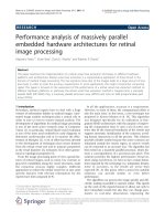
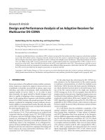
Figure 1.1 Albedo collections from the ground and the surrounding by the rear
side of the bifacial PV module [23]. 5
Figure 2.1 Schematic of a standard monofacial (left) and bifacial (right) silicon
wafer solar cell [36]. The rear side of the bifacial cell structure
shown above is without texture. However, almost all commercial
bifacial cells are textured on both sides to enhance light trapping
and hence current response. 11
Figure 2.2 Double-junction bifacial solar cell proposed by Mori in 1960 [47]. 12
Figure 2.3 (a) Bifacial solar cell with p-n-n
+
structure. (b) Bifacial cell with
dielectric passivation. After Refs. [51, 52]. 13
Figure 2.4 Photograph of a rooftop bifacial PV module installation with white
coating on rooftop [62]. 14
Figure 2.5 Photograph of vertically installed bifacial PV modules serving as
noise barrier in Switzerland [73]. 15
Figure 2.6 (a) Daily generation curves of bifacial and monofacial modules in
Japan [71], (b) Typical daily electricity demand curve [74] 16
Figure 2.7 Schematic of the concentrator with bifacial solar cells presented by
Ortabasi [80]. 18
Figure 2.8 Schematic of a flat plate static concentrator using bifacial solar cells
[70]. 19
Figure 2.9 PV Sun-shading element with bifacial solar cells and semi-
transparent reflector sheet [69]. 20
Figure 2.10 Bifacial PV element applied as the roof of a car park. 20
Figure 2.11 Schematic of a bifacial solar cell I-V tester with one light source
[103]. 26
Figure 3.1 Cross-section of a standard c-Si wafer based PV module (not to
scale) [112]. 29
Figure 3.2 Flow chart of the c-Si PV module fabrication process. 29
Figure 3.3 Photographs of ribbons soldered on back and front of c-Si solar
cells (top) and a two-cell string (bottom). 30
Figure 3.4 Current-voltage characteristics of a typical c-Si wafer solar cell.
Also shown are the various electrical parameters. 33
Figure 3.5 Measured reflectance of the black cloth which was used to cover the
non-illuminated side of the bifacial module during I-V
measurement. 35
XI
Figure 3.6 Measured external quantum efficiency (EQE) curve of a typical c-Si
wafer solar cell. 36
Figure 4.1 Simulated bifacial 1.x efficiency and gain-efficiency product for two
fictitious bifacial solar cells with different electrical parameters as a
function of the irradiance gain. 50
Figure 4.2 Simulated bifacial 1.x efficiency and gain-efficiency product for the
cells with different I
sc-r
/I
sc-f
. 51
Figure 4.3 (a) Simulated effect of front side FF on the bifacial FF of the cell.
(b) Simulated bifacial 1.x efficiency and gain-efficiency product for
cells with different front side FF. 52
Figure 4.4 (a) Simulated effect of front side V
oc
on the bifacial V
oc
of the cell.
(b) Simulated bifacial 1.x efficiency and gain-efficiency product for
cells with different V
oc-f
. 53
Figure 4.5 Simulated bifacial 1.x efficiency and gain-efficiency product for the
cells with different front side I
sc
. 54
Figure 4.6 Simulated effect of increasing various solar cell parameters on (a)
the bifacial 1.x efficiency and (b) the gain-efficiency product. 55
Figure 5.1 Measured I-V parameters (symbols) of the bifacial module, for
single-sided illumination from front and rear as described in Table
5.1. (a) V
oc
, (b) I
sc
, (c) FF, and (d) efficiency. Also shown (solid
lines) are the simulated results calculated from the two
measurements indicated by the solid symbols. 68
Figure 5.2 Measured and simulated power of the bifacial module for the front
and rear side illumination (single-sided illumination). The
simulations are performed using the two measurements indicated by
the solid symbols. 69
Figure 5.3 Simulated V
oc
of the bifacial module for bifacial illumination. 71
Figure 5.4 Simulated FF of the bifacial module for bifacial illumination. 71
Figure 5.5 Simulated efficiency of the bifacial module for bifacial illumination. 72
Figure 5.6 Simulated power of the bifacial module for bifacial illumination. 73
Figure 5.7 Simulated power gain from a bifacial module as compared to the
monofacial module of similar type. 73
Figure 6.1 Schematic sketch (not to scale) showing various light paths in a
glass/ backsheet PV module with bifacial solar cells. 76
Figure 6.2 Schematics of module structures (not to scale) (a) glass/cell/glass,
(b) glass/cell, (c) glass/cell/backsheet 79
Figure 6.3 Measured (a) reflectance and (b) transmittance for glass/cell/glass,
glass/cell, and glass/cell/backsheet structures in the long-
wavelength region of the usable solar spectrum. 79
XII
Figure 6.4 Light absorptance for various module structures and cell IQE (rear
side). 81
Figure 6.5 Calculated relative change in cell I
sc
for different module structures. 82
Figure 6.6 Measured (a) reflectance and (b) normalized angular backscattering
luminous intensity of the backsheet (at 632 nm wavelength). 85
Figure 6.7 Sketch of light paths describing the light which is scattered from the
backsheet in the cell-gap region, reaching (a) the rear side and (b)
the front side of the bifacial solar cell in glass/backsheet modules. 86
Figure 6.8 Simulated current gain in a glass/backsheet PV module due to the
cell-gap region as compared to a glass/glass module structure. 88
Figure 6.9 Photographs of (a) glass/cell/backsheet (group 5) and (b)
glass/cell/glass (group 2) mini-modules fabricated with bifacial
solar cells. 90
Figure 6.10 Normalised measured module current for glass/glass and
glass/backsheet structures with varying cell gap. Also shown are the
simulated results. 91
Figure 6.11 Relative change in power gain, total cost and $/W
p
cost of glass/
backsheet modules with varying cell gap as compared to glass/glass
modules. The analysis is with respect to STC measurements. 94
Figure 7.1 Additional resistive loss components in a PV module (over and
above solar cell series resistance). 100
Figure 7.2 Schematics of different module structures fabricated using bifacial
cells and their nomenclature. Each structure may be illuminated (or
measured) from the front or the rear. 102
Figure 7.3 Schematics of the mini-module structures (not to scale) (a)
glass/EVA/ cell, (b) glass/EVA/cell/EVA/glass. 104
Figure 7.4 Photographs of (a) mini-module structure of Figure 7.3(a) fabricated
with bifacial solar cells and (b) 4-cell bifacial glass/glass module. 112
Figure 7.5 Measured EQE of bifacial cell before and after encapsulation in
mini-module structure under front side illumination (right). Also
shown are the schematics of the corresponding structures and their
illumination methods (left). 113
Figure 7.6 (a) Measured reflectance and transmittance and (b) absorptance for
glass/ cell/glass and glass/cell module structures and IQE of the cell
(rear side) in the long-wavelength region of the usable solar
spectrum. 114
Figure 7.7 Bifacial module structure (left) and optical losses (right) under front
side illumination. 114
Figure 7.8 Module I-V curves: As measured and normalised to the bifacial
solar cell measurement. 116
XIII
Figure 7.9 Cell-to-module loss components for the front side illumination in a
4-cell bifacial PV module under STC. 117
Figure 7.10 Measured EQE of bifacial solar cell before and after encapsulation
in mini-module structure under rear side illumination (right). Also
shown are schematics of the corresponding structures with the
illumination methods (left). 118
Figure 7.11 Bifacial module structure (left) and optical losses (right) under rear
side illumination. 119
Figure 7.12 Optical, mismatch, resistive and total CTM losses for a 4-cell
bifacial PV module under bifacial illumination. 120
Figure 8.1 Photographs of outdoor bifacial module performance measurement
setup at NUS. 124
Figure 8.2 Schematic showing the direction and tilt angles of the bifacial and
monofacial modules. 125
Figure 8.3 Measured performance ratio (PR) of the two module types (bifacial,
monofacial) for three different tilt angles. 127
Figure 8.4 Average I
sc
gain (over 6 weeks of data) throughout the day at
different tilt angles. The measurements were performed during
different time periods 129
Figure 8.5 Measured I
sc
gain versus the diffuse/global irradiance ratio, for a
45° tilt angle of the modules. 130
Figure 8.6 Normalised power for a vertically installed bifacial module (facing
east-west) and a 10° tilted bifacial module (facing south) throughout
the day (averaged over a period of two weeks). 131
Figure 8.7 Performance ratio (horizontal) for a vertically installed bifacial
module (facing east-west) and a 10° tilted bifacial module (facing
south). 132
Figure 8.8 Relative LCOE reduction with the energy gain of a bifacial PV
system. 134
XIV
LIST OF TABLES
Table 2.1 Comparison of fabrication processes for bifacial and monofacial
solar cells on p-type monocrystalline silicon wafers [36]. 23
Table 4.1 Front and rear side electrical parameters for two fictitious bifacial
solar cells. 49
Table 5.1 Measured front and rear side electrical parameters of the
commercial silicon wafer based bifacial PV module. 67
Table 6.1 Structures of the samples fabricated for cell transmittance
measurements. 78
Table 6.2 Details of the fabricated single-cell mini-module samples. To mimic
the cell gap, a non-reflecting black sheet was encapsulated into the
mini-modules in the plane of solar cell. 89
Table 6.3 Distribution of components cost for a 60-cell c-Si PV module. 93
Table 7.1 Measurement of bifacial cell and different mini-module structures
for loss calculation under front side illumination. 113
Table 7.2 Simulated module electrical parameters and mismatch loss
calculation. 115
Table 7.3 I-V parameters of 4-cell modules and calculation of resistive loss. 116
Table 8.1 Reference assumptions for the LCOE calculation [175-177] 133
XV
LIST OF SYMBOLS AND ABBREVIATIONS
GW
Gigawatt
LCOE
Levelised cost of electricity
STC
Standard test conditions
BSF
Back surface field
CTM
Cell-to-module
LEO
Low Earth orbit
BIPV
Building integrated photovoltaics
IEC
International Electrotechnical Commission
PECVD
Plasma-enhanced chemical vapour deposition
BBr
3
Boron tribromide
ARC
Antireflection coating
AM1.5G
Air mass 1.5 Global
1-Sun
An irradiance of 1000 W/m
2
I-V
Current-voltage
EQE
External quantum efficiency
IQE
Internal quantum efficiency
W
peak
STC rating of PV modules
I
sc
Short-circuit current
FF
Fill factor
V
oc
Open-circuit voltage
Efficiency
Photon flux corresponding to AM1.5G irradiance
R
cell
/ T
cell
/ A
cell
Measured reflectance/transmittance/absorptance of cell
pFF
Pseudo fill factor
Efficiency measured for front side illumination at STC
XVI
Bifacial 1.x efficiency
Short-circuit current
measured for front side illumination at STC
Open-circuit voltage
measured for front side illumination at STC
Fill factor measured for front side illumination at STC
Fill factor measured for rear side illumination at STC
Short-circuit current measured for rear side illumination at STC
Effective fill factor under simultaneous bifacial illumination
Effective V
oc
under simultaneous bifacial illumination
Relative current gain
Irradiance gain
Irradiance factor
Gain-efficiency product
Irradiance at STC conditions (i.e. AM1.5G)
Irradiance on the front side of the bifacial device
Irradiance on the rear side of the bifacial device
Resistive power losses
Relative resistive power losses
Dark saturation current of solar cell
q
Electronic charge
Output power of bifacial module for bifacial illumination
Module one-diode model parameter equivalent to dark
saturation current in solar cell one-diode model
Lumped shunt resistance of the module
Reflectance/ Transmittance of encapsulated module structures
Absorption in front side glass and EVA
External/Internal quantum efficiency of the cell for rear-side
illumination
External quantum efficiency of the reference module for front-
side illumination
XVII
Reflectance/Transmittance of the bifacial cell measured from the
rear side
Weighted average reflectance of the backsheet corresponding to
AM1.5G
Incident light intensity
Incident irradiance on rear side of the bifacial cell due to
backsheet
Incident irradiance on front side of the bifacial cell due to
backsheet
Irradiance at a direction after reflection from the unit
backsheet area
Relative increase in module
due to cell-gap region of the
backsheet
Optical loss due to the front side encapsulation
Optical loss due to the rear side encapsulation
Mismatch loss in bifacial PV module under front-side STC
illumination
Resistive loss in bifacial PV module under front-side STC
illumination
Optical loss in bifacial PV module under bifacial illumination
Mismatch loss in bifacial PV module under bifacial illumination
Resistive loss in bifacial PV module under bifacial illumination
PR
Performance ratio
H
in-plane
Irradiance in the module plane
H
horizontal-plane
Irradiance on the horizontal plane
PR
hor
Performance ratio calculated using irradiance on horizontal
plane
BOS
Balance of system (all components of a PV system excluding the
PV modules)
1
CHAPTER 1 - INTRODUCTION
1.1 Solar photovoltaics: A promising renewable energy
source
With the rapid growth in world population and industrialization of
nations, the global energy demand is increasing exponentially. Traditionally,
this demand for energy has been fulfilled by conventional fossil fuel-based
energy sources (oil, coal and natural gas). Currently, more than 80% of
mankind's energy needs are met by fossil fuels [1]. The major problems with
fossil energy sources are: 1) these sources are finite in nature and therefore are
depleting 2) they emit greenhouse gases into the atmosphere. On the other
hand, renewable energy sources, such as solar, wind, geothermal, hydro, tidal,
and biomass, are environmentally clean and provide sustainable energy
services based on the use of routinely available, indigenous resources which
can be replenished [2, 3]. As a result, renewable energy is increasingly being
used in the total energy mix to meet global electricity needs. Energy supply
based on renewable energy sources can provide better energy security to the
world and is a promising solution for a clean and sustainable future.
Among various renewable energy sources, solar energy is a widely
accessible and environmentally friendly source which has the potential to meet
mankind's global energy requirements. The solar energy that hits the earth’s
surface in one hour is equivalent to mankind's total annual energy
consumption [4]. One possible way to use solar energy is the direct conversion
of incident solar energy to electricity by photovoltaic (PV) technology using
2
semiconductor materials. PV technology generates direct-current electrical
power from semiconductors when they are illuminated by light. PV is
considered a clean, sustainable, renewable energy technology that can help to
meet mankind's increasing global energy needs, whilst reducing the adverse
impacts of fossil fuel based energy sources [5]. Being distributed in nature, the
use of PV technology can effectively minimize both transmission loss and
costs when the generation is located close to the demand load of end-users [6].
In addition, solar PV technology provides a convenient way of generating
power in remote locations where the electricity grid is not easily accessible,
e.g. for powering remote villages, communication equipment and weather
monitoring stations. PV is also ideal for supplying power for satellites and
space vehicles [7].
With the above-mentioned key advantages, the emerging major
economies are already investing substantially in PV research, development
and deployment. Over the last two decades, PV technology has grown with an
annual growth rate of 30-40% per year, and by 2012 more than 100 GW of
cumulative PV capacity had been installed worldwide [8]. This figure is
expected to reach more than 280 GW by 2017 [8].
1.2 Cost of PV electricity and benefits of bifacial PV modules
Despite the advantage of utilizing a virtually unlimited energy source,
the penetration of PV power in the global energy supply is essentially dictated
by economics. Today, PV comprises only ~0.1% of the global electricity
portfolio [9]. Hence the main focus of the PV technology research is towards
3
cost reduction, in order to achieve an energy cost that is comparable, or even
lower, than the conventional fossil fuel based energy sources.
To estimate the cost of electricity generated using emerging renewable
energy technology, such as PV, the metric "levelised cost of electricity"
(LCOE) is now widely used [10, 11]. LCOE provides an economic assessment
of renewable energy technologies by allowing them to be compared with the
grid electricity prices. The LCOE is the cost per unit of electricity produced
(or saved) by the PV system over its technical lifetime. It is a measure of the
total life cycle cost (including initial capital cost, operation and maintenance
costs, etc.) discounted back to the base year. For a PV power system with a
total lifetime of n years, the LCOE can be calculated by dividing the
accumulated cost by the generated electricity over the entire lifetime of the
system, as given by Equation (1.1) [11-13]:
(1.1)
where
is the initial capital cost,
is the annual operation and maintenance
cost in year t,
is the electricity produced in the respective year, i is the
interest rate (discount rate) and d is the annual system degradation rate. In
2013, a typical LCOE range of 0.08 - 0.14 Euro
2013
per kWh of PV electricity
was reported [14].
The ongoing aim is to reduce the LCOE further, which can be achieved
in two possible ways as described by Equation (1.1): 1) reducing the initial
capital cost
(or price per W
p
), 2) increasing the generated electricity
.
4
Reduction in initial capital cost has been driven mainly by economies of
manufacturing scale, improvement in manufacturing technology, reduction in
material cost, and increase in device efficiency. Most PV researchers are
working towards the cost reduction via solar cell efficiency improvements,
which is measured under standard test conditions (STC). To further increase
the solar cell efficiency, a number of advanced solar cell concepts are being
explored, such as LBSF (local back surface field) or PERC (passivated emitter
rear cell) solar cells, back contact solar cells, multi-junction solar cells, hetero-
junction solar cells, etc. [15-18]. However, the advanced solar cell concepts
lead to an increase in cell complexity, additional processing steps and
associated cost, which result in diminishing returns [19]. Thus, cost reduction
via advanced cell concepts is very challenging.
In the second approach, the LCOE can be reduced by increasing the
performance and energy yield of PV systems for the same installed capacity
(in kW
peak
). A promising PV technology to increase the energy yield is the
bifacial solar cell and module structure. Bifacial solar cells can convert
incident sunlight to electrical energy from both sides of the cells. Thus,
bifacial PV modules (fabricated with glass/glass structure using bifacial solar
cells) can significantly increase the energy yield as compared to conventional
monofacial modules by utilizing the albedo (light scattered from the ground
and the surroundings) when operating in real-world outdoor conditions [20,
21]. Figure 1.1 shows the additional light collection on the rear side of a
bifacial module due to the albedo from the ground and surroundings [22].
These module types can enhance the power density (power per unit area on the
5
Figure 1.1 Albedo collections from the ground and the surrounding by the rear side
of the bifacial PV module [23].
front surface) by using the material more efficiently, and thus area-related
costs for a PV power system such as land, cabling, installation structure etc.
can be reduced [24]. Various simulation and experimental studies show that
without any special features and modifications to the installation conditions, a
performance gain in the range of 10-20% for bifacial modules compared to
monofacial modules is easily achievable in outdoor conditions [20, 25]. With
specific installation conditions, a power gain up to 50% has been reported for
bifacial modules as compared to monofacial modules [21].
Additionally, due to the reduced metal fraction on the rear side, bifacial
design helps in reducing the loss which occurs in conventional silicon solar
cells with full rear surface Al back surface field (BSF) structures, mainly due
to parasitic light absorption in the aluminium and high surface recombination
at the Si-metal interface, especially in thin wafer solar cells [26-28]. Also, the
warping effect resulting from the differential thermal expansion between
aluminium and silicon is reduced in bifacial solar cells, as compared to the
Diffuse light
Direct light
Bifacial module
6
conventional Al-BSF design [29, 30]. This improves the manufacturing yield
at both the cell and module level by reducing the wafer and cell breakage, and
also allows the use of thinner wafers. Thus, one of the motivations behind the
development of bifacial solar cells was to improve the cell performance by
minimizing the above mentioned loss and problems.
Due to the potential benefits of bifacial cells and modules, many
researchers are exploring bifacial PV technologies and the PV industry is
looking forward to manufacture bifacial solar cell and modules on mass scale
[31].
1.3 Thesis motivation and objectives
Despite the obvious advantages of bifacial solar cells and modules, and
their promising potential for cost reductions of PV power, the share of bifacial
modules in the market as of today is almost negligible. There are a number of
challenges and problems associated with the deployment of the bifacial
modules in solar PV systems, as follows:
1. Characterisation: No established standards to characterise bifacial solar
cells and modules [32-34]
2. Rating and standardisation: No standard method is available to rate the
bifacial cells and modules using indoor measurements [35].
3. Bifacial solar cell (and module) fabrication: Additional complex steps
in the cell fabrication process and associated costs [36-38]