A suggested analytical solution of oblique crack effect on the beam vibration
Bạn đang xem bản rút gọn của tài liệu. Xem và tải ngay bản đầy đủ của tài liệu tại đây (1.34 MB, 20 trang )
INTERNATIONAL JOURNAL OF
ENERGY AND ENVIRONMENT
Volume 6, Issue 3, 2015 pp.227-246
Journal homepage: www.IJEE.IEEFoundation.org
ISSN 2076-2895 (Print), ISSN 2076-2909 (Online) ©2015 International Energy & Environment Foundation. All rights reserved.
A suggested analytical solution of oblique crack effect on the
beam vibration
Muhannad Al-Waily
Mechanical Engineering department, Faculty of Engineering, Al-Kufa University, Ministry of Higher
Education & Scientific Research, Iraq.
Abstract
In this research development the derivation of general equation of motion for beam with crack effect
presented in paper [1], to derivation the general equation of motion of beam with oblique crack effect.
The derivation of equation of motion of beam included suggested analytical solution for effect of oblique
in crack on the natural frequency of beam with added the effect oblique of crack in stiffness (EI) beam
with calculated the equivalent stiffness, (EI), for a rectangular beam to involve an exponential function
with depth, location and ordination of oblique crack effect, with solution of assuming equivalent stiffness
beam (EI) by using of Fourier series method. The natural frequency of a cracked beam with simply
supported beam is investigated analytically, with solution of general equation of motion of beam with
oblique crack effect, and numerically by finite element method, with using of ANSYS program ver. 14,
for different crack depth, location and crack orientation effect and the results are compared. The same
beam materials studied in paper, [1], are study in this research as, low carbon steel, Alloys Aluminum,
and Bronze materials with different beam length, depth and crack orientation. A comparison made
between analytical results from theoretical solution of general equation of motion of beam with oblique
crack effect with numerical solution by finite element method with using ANSYS results, where the
biggest error percentage is about (1.8 %). The results of natural frequency of beam shows that the natural
frequency of beam increasing with increasing the crack orientation, the effect of crack orientation
decreasing with increase the orientation of crack.
Copyright © 2015 International Energy and Environment Foundation - All rights reserved.
Keywords: Vibration crack beam; Oblique crack effect; Health monitoring; Theoretical vibration
oblique crack beam; Frequency of beam with crack orientation effect; Simply supported crack beam;
Finite element method; Finite element crack beam.
1. Introduction
All structures are prone to damage, may be due to over-stressing in operation or due to extreme
environmental conditions or due to any accidental event. Crack present in the component may grow
during service and may result in the component failure once they grow beyond a critical limit. It is
desirable to investigate the damage occurred in the structure at the early stage to protect the structure
from possible catastrophic failures, [2].
Vibration principles are the inherent properties of the physical science applicable to all structures
subjected to static or dynamic loads. All structures again due to their rigid nature develop some
irregularities in their life span which leads to the development of crack. The problem on crack is the
International Journal of Energy and Environment (IJEE), Volume 6, Issue 3, 2015, pp.227-246
ISSN 2076-2895 (Print), ISSN 2076-2909 (Online) ©2015 International Energy & Environment Foundation. All rights reserved.
228
basic problem of science of resistance of materials. Considering the crack as a significant form of such
damage, its modelling is an important step in studying the behaviour of damaged structures, [3].
The purpose of the present work is drive the general equation of motion of beam with oblique crack
effect, evaluated the natural frequency of beam with effect of crack orientation with different crack depth
and location. The theoretical study included evaluated the equivalent stiffness of beam with oblique
crack effect by using Fourier series method, and then, driving the general equation of natural frequency
of beam with effect of orientation of oblique crack effect.
2. Literature review
Many studies were performed to examine the vibration study of different types of crack beam, as,
Muhannad Al-Waily [1] and [4], in this researches the natural frequency of a cracked beam with different
supported, simply and clamped beam, is investigated analytically and numerically by finite element
method with using of ANSYS program ver. 14, [1], and analytically and experimental, [4], with different
crack depth and location effect and the results are compared. The analytical results of the effect of a
crack in a continuous beam are calculated the equivalent stiffness, EI, for a rectangular beam to involve
an exponential function with depth and location of crack effect, with solution of assuming equivalent
stiffness beam (EI) by using of Fourier series method. And, the different beam materials studied with
different beam length and depth and crack depth and location effect.
Kaushar H. Barad et al [2], during the last few decades, intense research on the detection of crack using
the vibration based techniques has been done and various approaches have been developed by
researchers. In the presented paper, detection of the crack presence on the surface of beam-type structural
element using natural frequency is presented. First two natural frequencies of the cracked beam have
been obtained experimentally and used for detection of crack location and size. Also, the effect of the
crack location and the crack depth on the natural frequency is presented.
SachinS.Naik et al [5], the paper presented the full formulation for a crack model for analyzing the triply
coupled free vibration of both Timoshenko (short) and Euler–Bernoulli (long) shaft beams based on
compliance approach in the presence of a planar open edge crack in an arbitrary angular orientation with
a reference direction. The compliance coefficients to account for the local flexibility due to the crack for
both the beams have been obtained through the concept of strain energy release rate and crack tip stress
field given in terms of the stress intensity factors. The variation of the coefficients with crack orientation
is presented. Equations governing the free transverse and torsion vibrations are derived and solved.
Ashish K. Darpe [6], a finite element model of a rotor with slant crack is presented. Based on fracture
mechanics, a new flexibility matrix for the slant crack is derived that accounts for the additional stress
intensity factors due to orientation of the crack compared to the transverse crack. Comparison between
rotor with slant and transverse crack is made with regard to the stiffness coefficients and coupled
vibration response characteristics. Compared to transverse crack, the stiffness matrix for slant crack is
more populated with additional cross coupled coefficients. The influence of angle of orientation of the
slant crack on the stiffness values is also investigated.
Murat Kisa et al [7], this paper presented a novel numerical technique applicable to analyses the free
vibration analysis of uniform and stepped cracked beams with circular cross section. In this approach in
which the finite element and component mode synthesis methods are used together, the beam is detached
into parts from the crack section. These substructures are joined by using the flexibility matrices taking
into account the interaction forces derived by virtue of fracture mechanics theory as the inverse of the
compliance matrix found with the appropriate stress intensity factors and strain energy release rate
expressions.
H. Nahvi et al [8], in this paper, an analytical, as well as experimental approach to the crack detection in
cantilever beams by vibration analysis is established. An experimental setup is designed in which a
cracked cantilever beam is excited by a hammer and the response is obtained using an accelerometer
attached to the beam. To avoid non-linearity, it is assumed that the crack is always open. To identify the
crack, contours of the normalized frequency in terms of the normalized crack depth and location are
plotted. The intersection of contours with the constant modal natural frequency planes is used to relate
the crack location and depth.
Hai-Ping Lin [9], an analytical transfer matrix method is used to solve the direct and inverse problems of
simply supported beams with an open crack. The crack is modeled as a rotational spring with sectional
flexibility. By using the Timoshenko beam theory on two separate beams respectively and applying the
compatibility requirements of the crack, the characteristic equation for this cracked system can be
International Journal of Energy and Environment (IJEE), Volume 6, Issue 3, 2015, pp.227-246
ISSN 2076-2895 (Print), ISSN 2076-2909 (Online) ©2015 International Energy & Environment Foundation. All rights reserved.
229
obtained explicitly. This characteristic equation is a function of the eigenvalue (natural frequency), the
location of the crack and its sectional flexibility. When any two natural frequencies in this cracked
system are measured, the location and the sectional flexibility can be determined using the characteristic
equation.
The objective of this paper is to study the effect of crack orientation, depth and position on the natural
frequency of the beam by using of analytical solution of general equation of motion of beam with oblique
crack effect and compared with numerical results evaluated by finite element method with using of
Ansys Program Ver. 14. To achieve the above objectives, analytical solution is developed for dynamic
analysis of beam with and without crack effect to evaluate the fundamental natural frequency of beam by
using the analytical solution of general equation of motion of beam with oblique crack effect, by building
a computer program for analytical solution using Fortran power station Ver. 4.0 program.
3. Mathematical model
Consider the beam with oblique crack, through the thickness of beam, shown in Figure 1a, having the
following geometrical and material characteristics (l, w, d, d
c
,
,
, E, I
x
, ), where; E-modulus of
elasticity; and -density of beam and other notations as shown in the figure. The beam is supposed to be
loaded with a bending moment and to have a uniform transverse surface crack of depth a located at a
given position x
c
from the left edge of the beam.
Figure 1. Dimensions of Beam with oblique crack
Assuming the oblique crack, through the thickness of beam, is vertical crack with crack depth (d
v
c
)and
horizontal crack with crack width (d
h
c
),as shown in Figure 1b, divided the effect of oblique crack in
vertical and horizontal direction of beam effect.
To studying the effect of oblique crack suggested the beam with vertical crack (d
v
c
)only and neglected
the effect of horizontal crack effect, since the effect of horizontal crack less than the effect of vertical
crack. And derivation the general equation of motion of beam with crack effect with using the equivalent
stiffness of beam with crack effect, EI, for vertical crack depth only (d
v
c
), as,
()
()
Crack
Vertical Crack
Horizontal Crack
International Journal of Energy and Environment (IJEE), Volume 6, Issue 3, 2015, pp.227-246
ISSN 2076-2895 (Print), ISSN 2076-2909 (Online) ©2015 International Energy & Environment Foundation. All rights reserved.
230
d
v
c
=
. cos
(1)
where, d
c
is the oblique crack depth.
And, with using the general equation of beam vibration can be written as, [10],
2
x
2
EI
x
2
w
x
2
x, t
+ A
x
2
w
t
2
x, t
= 0 (2)
The effect of a crack in a continuous beam and calculated the stiffness, EI, for a rectangular beam to
involve an exponential function given by, [11]:
EI
x
=
EI
0
1+C exp
2
xx
c
d
(3)
where, C =
I
0
I
c
I
c
, for, I
0
=
wd
3
12
and I
c
=
w
dd
c
3
12
, and, w, d are the width and depth of the beam, x is
the position along the beam, and x
c
the position of the crack and, is a constant equal to (0.667), [11].
To adding the effect of the oblique crack suggested to changing the value of moment of inertia of crack
plate (I
c
)with moment of inertia of oblique crack (I
obl
c
), as,
I
obl
c
=
w
dd
v
c
3
12
(4)
where,
d
v
c
is depth of crack in vertical direction of beam defined as in Eq. 1.
And the value of C in Eq. 3, become
C =
I
0
I
obl
c
I
obl
c
(5)
Then, by substation Eq. 5 into Eq. 3, get,
EI
x
=
EI
0
.I
obl
c
I
obl
c
+
I
0
I
obl
c
exp
2
xx
c
d
(6)
The mass for the beam can be calculated by,
A
x
= w d = A (7)
For vibration analysis of the beam having a crack with a finite length, relation Eq. 6 can be expanded as a
sum of sine and cosine functions in the domain 0 x L by Fourier series, as,
EI = A
o
+
A
n
cos
2n x
L
n=1
+
B
n
sin
2n x
L
n=1
(8)
where, A
o
, A
n
, and B
n
are Fourier series constant can be evaluated as, [12],
A
o
=
1
L
EI
x
dx
L
0
=
1
L
EI
0
. I
obl
c
I
obl
c
+
I
0
I
obl
c
exp
2
x x
c
d
dx
L
0
A
n
=
2
L
EI
x
cos
2n x
L
dx
L
0
=
2
L
EI
0
. I
obl
c
I
obl
c
+
I
0
I
obl
c
exp
2
x x
c
d
cos
2n x
L
dx
L
0
B
n
=
2
L
EI
x
sin
2n x
L
dx
L
0
=
2
L
EI
0
.I
obl
c
I
obl
c
+
I
0
I
obl
c
exp
2
xx
c
d
sin
2n x
L
dx
L
0
(9)
International Journal of Energy and Environment (IJEE), Volume 6, Issue 3, 2015, pp.227-246
ISSN 2076-2895 (Print), ISSN 2076-2909 (Online) ©2015 International Energy & Environment Foundation. All rights reserved.
231
By integral Eq. 9 by x, using Simpson’s rule integration method [13], get the Fourier series constant, as,
f
x
dx
x
f
x
i
=
1
3
x
f
x
i
m
d
f
x
i
+ 4
f
x
s
m
d
1
s=1,3,5,
+ 2
f
x
s
m
d
2
s=2,4,6,
+ f
x
f
(10)
where, x
i
= 0 and x
f
= L, and m
d
is the subdivisions of interval
x
i
, x
f
, usually even number. And,
x
s
= x
i
+
x
f
x
i
m
d
s
Then,
A
o
=
1
3L
x
f
x
i
m
d
EI
0
. I
obl
c
I
obl
c
+
I
0
I
obl
c
exp
2
x
i
x
c
d
+
4
EI
0
. I
obl
c
I
obl
c
+
I
0
I
obl
c
exp
2
x
s
x
c
d
m
d
1
s=1,3,5,
+
2
EI
0
. I
obl
c
I
obl
c
+
I
0
I
obl
c
exp
2
x
x
c
d
m
d
2
s=2,4,6,
+
EI
0
. I
obl
c
I
obl
c
+
I
0
I
obl
c
exp
2
x
x
c
d
A
n
=
2
3L
x
f
x
i
m
d
EI
0
. I
obl
c
I
obl
c
+
I
0
I
obl
c
exp
2
x
i
x
c
d
cos
2n x
i
L
+
4
EI
0
. I
obl
c
I
obl
c
+
I
0
I
obl
c
exp
2
x
s
x
c
d
cos
2n x
s
L
m
d
1
s=1,3,5,
+
2
EI
0
. I
obl
c
I
obl
c
+
I
0
I
obl
c
exp
2
x
s
x
c
d
cos
2n x
s
L
m
d
2
s=2,4,6,
+
EI
0
. I
obl
c
I
obl
c
+
I
0
I
obl
c
exp
2
x
x
c
d
cos
2n x
f
L
B
n
=
2
3L
x
f
x
i
m
d
EI
0
.I
obl
c
I
obl
c
+
I
0
I
obl
c
exp
2
x
i
x
c
d
sin
2n x
i
L
+
4
EI
0
.I
obl
c
I
obl
c
+
I
0
I
obl
c
exp
2
x
s
x
c
d
sin
2n x
s
L
m
d
1
s=1,3,5,
+
2
EI
0
.I
obl
c
I
obl
c
+
I
0
I
obl
c
exp
2
x
s
x
c
d
sin
2n x
s
L
m
d
2
s=2,4,6,
+
EI
0
.I
obl
c
I
obl
c
+
I
0
I
obl
c
exp
2
x
x
c
d
sin
2n x
f
L
(11)
Then, substation Eqs. 7 and 8 in to Eq. 2, get,
2
x
2
A
o
+
A
n
cos
2 n x
L
n=1
+
B
n
sin
2 n x
L
n=1
2
w
x
2
x, t
+ A
2
w
t
2
x, t
= 0 (12)
Then, by differential Eq. 12, get,
4
w
x
4
x, t
A
o
+
A
n
cos
2 n x
L
n=1
+
B
n
sin
2 n x
L
n=1
3
w
x
3
x, t
4 n
L
A
n
sin
2 n x
L
n=1
B
n
cos
2 n x
L
n=1
2
w
x
2
x, t
2 n
L
2
A
n
cos
2 n x
L
n=1
+
B
n
sin
2 n x
L
n=1
+ A
2
w
t
2
x, t
(13)
Assuming the effect of crack small on the deflection of beam, then can be assuming the behaviours of
beam with crack same the behaviours of beam without crack, as, [10], for simply supported beam,
International Journal of Energy and Environment (IJEE), Volume 6, Issue 3, 2015, pp.227-246
ISSN 2076-2895 (Print), ISSN 2076-2909 (Online) ©2015 International Energy & Environment Foundation. All rights reserved.
232
w
x
= A
n
sin
n
x
(14)
For,
1
l = ,
2
l = 2,
3
l = 3,
4
l = 4,
And, the general behavior of beam as a faction of x and time, as,
w
x, t
= A
n
sin
n
x
sin(t) (15)
Then, by substation Eq. 15 in to Eq. 13, get the general equation of motion for beam with crack effect as,
n
4
sin
n
x
A
o
+
A
n
cos
2 n x
L
n=1
+
B
n
sin
2 n x
L
n=1
+
n
3
cos
n
x
4 n
L
A
n
sin
2 n x
L
n=1
B
n
cos
2 n x
L
n=1
+
n
2
sin
n
x
2 n
L
2
A
n
cos
2 n x
L
n=1
+
B
n
sin
2 n x
L
n=1
2
sin
n
x
A = 0 (16)
By pre multiplying Eq. 16 by sin
n
x
and integral with x for 0 x l, get, the natural frequency of
beam with crack,
2
=
n
4
sin
n
x
2
A
o
+
A
n
cos
2 n x
L
n =1
+
B
n
sin
2 n x
L
n =1
+
n
3
sin
2
n
x
2 n
L
A
n
sin
2 n x
L
n =1
B
n
cos
2 n x
L
n =1
+
n
2
sin
n
x
2
2 n
L
2
A
n
cos
2 n x
L
n =1
+
B
n
sin
2 n x
L
n =1
dx
l
0
sin
n
x
2
A dx
l
0
(17)
By integral Eq. 17 by x, using Simpson’s rule integration method [13], get the natural frequency of beam
with crack effect, as,
f
x
dx
x
f
x
i
=
1
3
x
f
x
i
m
d
f
x
i
+ 4
f
x
s
m
d
1
s=1,3,5,
+ 2
f
x
s
m
d
2
s=2,4,6,
+ f
x
f
(18)
where, x
i
= 0 and x
f
= L, and m
d
is the subdivisions of interval
x
i
, x
f
, usually even number.
And, x
s
= x
i
+
x
f
x
i
m
d
s
Then,
2
=
1
3
x
f
x
i
m
d
n
4
sin
n
x
i
2
A
o
+
A
n
cos
2 n x
i
L
n =1
+
B
n
sin
2 n x
i
L
n =1
+
n
3
sin
2
n
x
i
2 n
L
A
n
sin
2 n x
i
L
n =1
B
n
cos
2 n x
i
L
n =1
+
n
2
sin
n
x
i
2
2 n
L
2
A
n
cos
2 n x
i
L
n =1
+
B
n
sin
2 n x
i
L
n =1
+
4
n
4
sin
n
x
s
2
A
o
+
A
n
cos
2 n x
s
L
n =1
+
B
n
sin
2 n x
s
L
n =1
+
n
3
sin
2
n
x
s
2 n
L
A
n
sin
2 n x
s
L
n =1
B
n
cos
2 n x
s
L
n =1
+
n
2
sin
n
x
s
2
2 n
L
2
A
n
cos
2 n x
s
L
n =1
+
B
n
sin
2 n x
s
L
n =1
m
d
1
s =1,3,5,
+
2
n
4
sin
n
x
s
2
A
o
+
A
n
cos
2 n x
s
L
n =1
+
B
n
sin
2 n x
s
L
n =1
+
n
3
sin
2
n
x
s
2 n
L
A
n
sin
2 n x
s
L
n =1
B
n
cos
2 n x
s
L
n =1
+
n
2
sin
n
x
s
2
2 n
L
2
A
n
cos
2 n x
s
L
n =1
+
B
n
sin
2 n x
s
L
n =1
m
d
2
s =2,4,6,
+
n
4
sin
n
x
f
2
A
o
+
A
n
cos
2 n x
f
L
n =1
+
B
n
sin
2 n x
f
L
n =1
+
n
3
sin
2
n
x
f
2 n
L
A
n
sin
2 n x
f
L
n =1
B
n
cos
2 n x
f
L
n =1
+
n
2
sin
n
x
f
2
2 n
L
2
A
n
cos
2 n x
f
L
n =1
+
B
n
sin
2 n x
f
L
n =1
1
3
x
f
x
i
m
d
sin
n
x
i
2
A+4
sin
n
x
s
2
A
m
d
1
s =1,3,5,
+2
sin
n
x
s
2
A
m
d
2
s =2,4,6,
+sin
n
x
f
2
A
(19)
By using of the building a computer program for analytical solution using Fortran power station 4.0
program, as shown in the flow chart in Figure 2, can be get the results of Eq. 19 to evaluated natural
International Journal of Energy and Environment (IJEE), Volume 6, Issue 3, 2015, pp.227-246
ISSN 2076-2895 (Print), ISSN 2076-2909 (Online) ©2015 International Energy & Environment Foundation. All rights reserved.
233
frequency of beam with oblique crack effect. The building program requirement input data of beam as,
the beam dimensions (length, depth and width of beam) and the mechanical properties of beam (modulus
of elasticity and density of beam). And, the output of program are the natural frequency of simply
supported beam with effect of crack orientation through the thickness of beam with various beam
materials (low carbon steel, Alloys Aluminum, and Bronze materials) and different crack size and
location effect. And then, the theoretical results evaluated with building program are compare with
numerical results evaluated with finite element method, with using Ansys program Ver. 14.
Figure 2. Flow chart of fortran computer program, for evaluating the natural frequency of beam with
crack orientation effect with different crack depth and location effect
Start
Input Data of Beam, Mechanical Properties, Modulus of Elasticity E and Density of Beam
= 0. 0.9.
= 0.
Evaluated Fourier Series Constant, A
o
, A
n
, and B
n
, Eq. 11
Evaluated equivalent stiffness beam (EI), Eq. 8
Evaluated the Natural Frequency of Beam, Eq. 19
= 0.1.
= 0.1.
Write Output the Natural frequency of beam with different Crack Orientation
Effect for Various Crack Depth and Location Effect.
End
Input Data of Beam, Dimensions of Beam, Depth (d), Width (w), and Length (L) of Beam
= 0 90
c
= 15
International Journal of Energy and Environment (IJEE), Volume 6, Issue 3, 2015, pp.227-246
ISSN 2076-2895 (Print), ISSN 2076-2909 (Online) ©2015 International Energy & Environment Foundation. All rights reserved.
234
4. Numerical model
The numerical study of simply supported beam with oblique crack effect studied, included evaluated the
natural frequency of beam with effect of crack orientation for different crack depth and location effect by
using finite element methods with using Ansys program Ver. 14, and the numerical results are compare
with the theoretical results.
The finite element method, by using Ansys program, using the three dimensional model were built and
the element (Solid Tet 10 node 187) were used. A sample of meshed beam is shown in Figure 3. for
different oblique crack location.
Figure 3. Mash of beam with different crack location
5. Results and discussion
The vibration results of beam with oblique crack effect includes the evaluation of the natural frequency
of different beam materials, with oblique crack effect of beam, included the effect of crack orientation,
crack size, crack location, of simply supported beam.
Where The mechanical properties of beam studded, [14], are,
b. Beam with Middle Crack Location
Side View of Mash in Crack Location
Top View of Mash in Crack Location
a. Beam with Side Crack Location
Side View of Mash in Crack Location
Top View of Mash in Crack Location
International Journal of Energy and Environment (IJEE), Volume 6, Issue 3, 2015, pp.227-246
ISSN 2076-2895 (Print), ISSN 2076-2909 (Online) ©2015 International Energy & Environment Foundation. All rights reserved.
235
Low Carbon Steel beam,
E=207 GPa, G=80 GPa, =7800 kg/m
3
, =0.3
Alloys Aluminum beam,
E=69 GPa, G=26 GPa, =2770 kg/m
3
, =0.33
Bronze beam,
E=115 GPa, G=45 GPa, =7650 kg/m
3
, =0.28
And dimensions beam,
Width of beam, w = 0.015 m
Depth of beam, d = 0.025 m
Length of beam, L = 1 m
The method studied to evaluate the natural frequency of beam with oblique crack effect are, theoretical
study and numerical study, by using ANSYS Program Version 14. The theoretical and numerical work
includes the study of the crack orientation effect of beam with different crack size (depth of crack),
different crack position, different beam dimensions (depth and length of beam) and simply supported
boundary conditions of beam.
The theoretical results compare with numerical results and shown the effect of the crack orientation of
different beam materials (low carbon steel, alloys Aluminum and bronze beam) with different crack
depth and location effect, as,
Figures 4 and5, shown theoretical and numerical results of natural of simply supported beam made of
low carbon steel materials with crack orientation effect for different crack depth and crack location
effect,(d
c
= 10%d, 30%d, 50%d, 70%d, 90%d), (x
c
= 10%L, 25%L, 40%L, 50%L), respectively.
Figures 6 and 7, shown theoretical and numerical results of natural of simply supported beam made of
alloys aluminum materials with crack orientation effect for different crack depth and crack location effect
(d
c
= 10%d, 30%d, 50%d, 70%d, 90%d), (x
c
= 10%L, 25%L, 40%L, 50%L), respectively.
Figures 8 and 9, shown theoretical and numerical results of natural of simply supported beam made of
bronze materials with crack orientation effect for different crack depth and different crack location effect
(d
c
= 10%d, 30%d, 50%d, 70%d, 90%d), (x
c
= 10%L, 25%L, 40%L, 50%L), respectively.
The theoretical results evaluated from solution of general equation of motion of beam, with crack effect
are compared with those obtained numerically by using the ANSYS Program (Version 14) for each
parameters effect studied as shown in Figures 4 to 9, shows a good approximation where the biggest
error percentage is about (1.5 %).
The Figures 4 to 9. Shows that the natural frequency of beam increasing with increasing the crack
orientation, since the vertical depth effect of crack decreasing with increases the crack angle, and then,
the stiffness of beam increasing with decreases of vertical crack depth effect. The, can be see the effect of
crack orientation cases decreasing the effect of crack through decreasing of the vertical crack depth
effect.
And, to shown the effect of crack depth on the natural frequency of simply supported beam, Figures 10
and 11 study the natural frequency of different materials simply supported beam with crack location
(x
c
=25%L, 50%L) and different crack depth with various crack orientation effect. The effect of crack size
as depth of crack for different beam materials, with different crack orientation, shows that the natural
frequency decreasing with increasing crack depth for different crack orientation, this is because the
changing in stiffness beam.
Also, the effect of crack location on the natural frequency of simply supported beam studding in Figures
12 and 13 for different beam materials with crack depth (d
c
=30%d, 70%d) and various oblique crack
orientation and location effect. The effect of crack location on the natural frequency of different beam
materials with various crack orientation effect shown that the natural frequency of beam decreases when
the crack near the middle location of beam more than other location of crack.
International Journal of Energy and Environment (IJEE), Volume 6, Issue 3, 2015, pp.227-246
ISSN 2076-2895 (Print), ISSN 2076-2909 (Online) ©2015 International Energy & Environment Foundation. All rights reserved.
236
Figure 4. Theoretical and numerical natural frequency for low carbon steel materials beam with various
crack angle and different crack depth effect, with crack location (x
c
=10%L and x
c
=25%L)
Crack Depth=d
c
= 10%d
Crack Depth=d
c
= 30%d
Crack Depth=d
c
= 50%d
Crack Depth=d
c
= 70%d
Crack Depth=d
c
= 90%d
Crack Location x
c
=10%L
Crack Location x
c
=25%L
International Journal of Energy and Environment (IJEE), Volume 6, Issue 3, 2015, pp.227-246
ISSN 2076-2895 (Print), ISSN 2076-2909 (Online) ©2015 International Energy & Environment Foundation. All rights reserved.
237
Figure 5. Theoretical and numerical natural frequency for low carbon steel materials beam with various
crack angle and different crack depth effect, with crack location (x
c
=40%L and x
c
=50%L)
Crack Depth=d
c
= 10%d
Crack Depth=d
c
= 30%d
Crack Depth=d
c
= 50%d
Crack Depth=d
c
= 70%d
Crack Depth=d
c
= 90%d
Crack Location x
c
=40%L
Crack Location x
c
=50%L
International Journal of Energy and Environment (IJEE), Volume 6, Issue 3, 2015, pp.227-246
ISSN 2076-2895 (Print), ISSN 2076-2909 (Online) ©2015 International Energy & Environment Foundation. All rights reserved.
238
Figure 6. Theoretical and numerical natural frequency for alloys aluminum materials beam with various
crack angle and different crack depth effect, with crack location (x
c
=10%L and x
c
=25%L)
Crack Depth=d
c
= 10%d
Crack Depth=d
c
= 30%d
Crack Depth=d
c
= 50%d
Crack Depth=d
c
= 70%d
Crack Depth=d
c
= 90%d
Crack Location x
c
=10%L
Crack Location x
c
=25%L
International Journal of Energy and Environment (IJEE), Volume 6, Issue 3, 2015, pp.227-246
ISSN 2076-2895 (Print), ISSN 2076-2909 (Online) ©2015 International Energy & Environment Foundation. All rights reserved.
239
Figure 7. Theoretical and numerical natural frequency for alloys aluminum materials beam with various
crack angle and different crack depth effect, with crack location (x
c
=40%L and x
c
=50%L)
Crack Depth=d
c
= 10%d
Crack Depth=d
c
= 30%d
Crack Depth=d
c
= 50%d
Crack Depth=d
c
= 70%d
Crack Depth=d
c
= 90%d
Crack Location x
c
=40%L
Crack Location x
c
=50%L
International Journal of Energy and Environment (IJEE), Volume 6, Issue 3, 2015, pp.227-246
ISSN 2076-2895 (Print), ISSN 2076-2909 (Online) ©2015 International Energy & Environment Foundation. All rights reserved.
240
Figure 8. Theoretical and numerical natural frequency for bronze materials beam with various crack
angle and different crack depth effect, with crack location (x
c
=10%L and x
c
=25%L)
Crack Depth=d
c
= 10%d
Crack Depth=d
c
= 30%d
Crack Depth=d
c
= 50%d
Crack Depth=d
c
= 70%d
Crack Depth=d
c
= 90%d
Crack Location x
c
=10%L
Crack Location x
c
=25%L
International Journal of Energy and Environment (IJEE), Volume 6, Issue 3, 2015, pp.227-246
ISSN 2076-2895 (Print), ISSN 2076-2909 (Online) ©2015 International Energy & Environment Foundation. All rights reserved.
241
Figure 9. Theoretical and numerical natural frequency for bronze materials beam with various crack
angle and different crack depth effect, with crack location (x
c
=40%L and x
c
=50%L)
Crack Depth=d
c
= 10%d
Crack Depth=d
c
= 30%d
Crack Depth=d
c
= 50%d
Crack Depth=d
c
= 70%d
Crack Depth=d
c
= 90%d
Crack Location x
c
=40%L
Crack Location x
c
=50%L
International Journal of Energy and Environment (IJEE), Volume 6, Issue 3, 2015, pp.227-246
ISSN 2076-2895 (Print), ISSN 2076-2909 (Online) ©2015 International Energy & Environment Foundation. All rights reserved.
242
(a) Low carbon steel beam
(b) Alloys aluminum beam
(c) Bronze beam materials
Figure 10. Theoretical natural frequency results for different simply supported beam materials with
various crack angle effect for different crack depth effect and location of crack (xc=25%L)
International Journal of Energy and Environment (IJEE), Volume 6, Issue 3, 2015, pp.227-246
ISSN 2076-2895 (Print), ISSN 2076-2909 (Online) ©2015 International Energy & Environment Foundation. All rights reserved.
243
(a) Low carbon steel beam
(b) Alloys aluminum beam
(c) Bronze beam materials
Figure 11. Theoretical natural frequency results for different simply supported beam materials with
various crack angle effect for different crack depth effect and location of crack (x
c
=50%L)
International Journal of Energy and Environment (IJEE), Volume 6, Issue 3, 2015, pp.227-246
ISSN 2076-2895 (Print), ISSN 2076-2909 (Online) ©2015 International Energy & Environment Foundation. All rights reserved.
244
(a) Low carbon steel beam
(b) Alloys aluminum beam
(c) Bronze beam materials
Figure 12. Theoretical natural frequency results for different simply supported beam materials with
various crack angle effect for different crack location effect and depth of crack (d
c
=30%d)
International Journal of Energy and Environment (IJEE), Volume 6, Issue 3, 2015, pp.227-246
ISSN 2076-2895 (Print), ISSN 2076-2909 (Online) ©2015 International Energy & Environment Foundation. All rights reserved.
245
(a) Low carbon steel beam
(b) Alloys aluminum beam
(c) Bronze beam materials
Figure 13. Theoretical natural frequency results for different simply supported beam materials with
various crack angle effect for different crack location effect and depth of crack (d
c
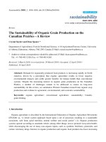
=70%d)
International Journal of Energy and Environment (IJEE), Volume 6, Issue 3, 2015, pp.227-246
ISSN 2076-2895 (Print), ISSN 2076-2909 (Online) ©2015 International Energy & Environment Foundation. All rights reserved.
246
6. Conclusion
Some concluding observations from the investigation of analytical and numerical study of natural
frequency of beam with crack orientation effect, for different crack depth and location effect, are given below,
1. The suggested analytical solution is a powerful tool for natural frequency of beam with crack
orientation, depth and location analysis study of simply supported beam with different materials
beam., by solution the general differential equations of motion of beam with oblique crack.
2. A comparison made between analytical results from solution of general equation of motion of beam
with crack effect with numerical results by finite elements method, with using Ansys program, shows
a good approximation.
3. The crack causes, as expected, a decrease in the stiffness of beam, and then, decreases the natural
frequencies of flexural vibrations of the beam.
4. The orientation of crack through the depth of beam causes divided the crack to two effect, vertical
and horizontal effect. And then, since the vertical depth decreasing with increasing the crack
orientation, then, the natural frequency of beam decreasing with increasing the crack angle.
5. The crack in the beam has an effect on the stiffness of the beam, this will affect the frequency of the
beam, so with increasing of the crack depth this will cause a decreasing the natural frequency of the beam.
6. The position of crack in the beam near the middle of the beam has more effect on the stiffness and
natural frequency of beam from the other positions.
References
[1] Muhannad Al-Waily 'Theoretical and Numerical Vibration Study of Continuous Beam with Crack
Size and Location Effect' International Journal of Innovative Research in Science, Engineering and
Technology, Vol. 2, No. 9, 2013.
[2] Kaushar H. Barad, D. S. Sharma, Vishal Vyas 'Crack detection in cantilever beam by frequency
based method' Elsevier, Procedia Engineering, Vol. 51, pp. 770-775, 2013.
[3] D.K. Agarwalla, D.R. Parhi ' Effect of Crack on Modal Parameters of a Cantilever Beam
Subjected to Vibration' Elsevier, Procedia Engineering, Vol. 51, pp. 665 – 669, 2013.
[4] Muhannad Al-Waily 'Theoretical and Experimental Vibration Study of Continuous Beam Wiht
Crack Depth and Location Effect' Indian Journal of Applied Research, Vol. 3, No. 9, 2013.
[5] SachinS.Naik, SurjyaK.Maiti ''Triply coupled bending–torsion vibration of Timoshenko and
Euler–Bernoulli shaft beams with arbitrarily oriented open crack' Journal of Sound and Vibration,
Vol. 324, pp. 1067–1085, 2009.
[6] Ashish K. Darpe ' Coupled vibrations of a rotor with slant crack' Journal of Sound and Vibration,
Vol. 305, pp. 172–193, 2007.
[7] Murat Kisa, M. ArifGurel 'Free vibration analysis of uniform and stepped cracked beams with
circular cross sections' International Journal of Engineering Science, Vol. 45, pp. 364–380, 2007.
[8] H. Nahvi, M. Jabbari ' Crack detection in beams using experimental modal data and finite element
model' International Journal of Mechanical Sciences, Vol. 47, pp. 1477–1497, 2005.
[9] Hai-Ping Lin ' Direct and inverse methods on free vibration analysis of simply supported beams
with a crack' Elsevier, Engineering Structures, Vol. 26, pp. 427–436, 2004.
[10] Singiresu S. Rao ‘Mechanical Vibration’ Addison-Wesley Publishing Book Company, 2000.
[11] M. I. Friswell and J. E. T. Penny ‘Crack Modeling for Structural Health Monitoring’ Structural
HealthMonitoring, Vol. 1, No. 2, pp. 139-148, 2002.
[12] A. Jeffrey 'Advanced Engineering Mathematics' Harcourt / Academic Press, 2002.
[13] H. Anton, IrlBivens, and Stephen Davis 'Calculus' Anton Textbooks, Inc, Seventh Edition, (2002).
[14] E. J. Hearn ‘Mechanics of Materials-1 An Introduction to the Mechanics of Elastic and Plastic
Deformation of Solids and Structural Materials, Third Edition’ E. J. Hearn, 1997.
Muhannad Al-Waily, Lecturer at Mechanical Engineering Department, Faculty of Engineering, Al-
Kufa University. Ph.D. in Mechanical Engineering, College of Engineering, Alnahrain University, Iraq.
Specialization: Applied Mechanics- Vibration Analysis, Composite Material, Crack Analysis, Health
Monitoring, Graduation Date: 2012. M.Sc. In Mechanical Engineering, College of Engineering,
University of Kufa, Iraq. Specialization: Applied Mechanics- Vibration Analysis, Composite Material,
Stress Analysis, Graduation Date: 2005. B.Sc. In Mechanical Engineering, College of Engineering,
University of Kufa, Iraq. Specialization: General Mechanics, Graduation Date: 2002. Research
Interests, Vibration Analysis, Stress Analysis under Static and Dynamic Loading, Composite Materials,
Fatigue and Creep Analysis of Engineering Materials, Mechanical Properties of Engineering Materials,
Control and Stability of Mechanical Application, Damage (Crack and Delamination Analysis) and other mechanical researches.
E-mail address: &