Digital and optical compensation of signal impairments for optical communication receivers
Bạn đang xem bản rút gọn của tài liệu. Xem và tải ngay bản đầy đủ của tài liệu tại đây (5.51 MB, 149 trang )
DIGITAL AND OPTICAL COMPENSATION OF SIGNAL
IMPAIRMENTS FOR OPTICAL COMMUNICATION
RECEIVERS
ADAICKALAVAN MEIYAPPAN
NATIONAL UNIVERSITY OF SINGAPORE
2014
DIGITAL AND OPTICAL COMPENSATION OF SIGNAL
IMPAIRMENTS FOR OPTICAL COMMUNICATION
RECEIVERS
ADAICKALAVAN MEIYAPPAN
(B.Eng.(Hons.), National University of Singapore, Singapore)
A THESIS SUBMITTED
FOR THE DEGREE OF DOCTOR OF PHILOSOPHY
DEPARTMENT OF ELECTRICAL AND COMPUTER ENGINEERING
NATIONAL UNIVERSITY OF SINGAPORE
2014
Declaration
I hereby declare that this thesis is my original work and it has been written by me in
its entirety. I have duly acknowledged all the sources of information which have been
used in the thesis.
This thesis has also not been submitted for any degree in any university previously.
Adaickalavan Meiyappan
1 August 2014
i
Acknowledgments
Foremost, I would like to express my sincere gratitude and appreciation to my Ph.D.
supervisor Prof. Pooi-Yuen Kam. I am greatly indebted for the research wisdom he
imparted and his invaluable guidance throughout my candidature. His countless hours
spent in our research discussions helped shape this thesis.
Special thanks to Dr. Hoon Kim, who previously co-supervised my research and
continuously provided helpful advice. I immensely benefited from his vast knowledge
in experimental optical communications. His deep insights, into the practical aspects
in research, which he shared with me improved the contributions of this thesis.
Additionally, I would like to thank my thesis committee members for their time
in reviewing this work.
I gratefully acknowledge the President’s Graduate Fellowship award from Na-
tional University of Singapore, supported by the Singapore MoE under AcRF Tier 2
Grant MOE2010-T2-1-101, for funding this postgraduate study.
Finally, my heartfelt thanks to my parents, sister, brother-in-law, and nephew,
whose unconditional support saw me through to the end of a fruitful four years of
doctoral endeavor.
ii
Contents
Declaration i
Acknowledgments ii
Contents iii
Summary iv
List of Tables v
List of Figures vi
List of Abbreviations vii
1 Introduction 1
1.1 Long Haul Transmission . . . . . . . . . . . . . . . . . . . . . . . . 1
1.2 Access Networks . . . . . . . . . . . . . . . . . . . . . . . . . . . . 4
1.3 Research Contributions . . . . . . . . . . . . . . . . . . . . . . . . . 8
1.4 Thesis Outline . . . . . . . . . . . . . . . . . . . . . . . . . . . . . . 9
2 Coherent Optical Systems 11
2.1 Modulation Formats . . . . . . . . . . . . . . . . . . . . . . . . . . . 11
2.1.1 Several 4-, 8-, and 16-Point Constellations . . . . . . . . . . . 11
2.1.2 BER Performance . . . . . . . . . . . . . . . . . . . . . . . . 13
iii
Contents
2.1.3 Differential Encoding Technique . . . . . . . . . . . . . . . . 14
2.2 Coherent Optical Transmission System . . . . . . . . . . . . . . . . . 16
2.2.1 Transmitter . . . . . . . . . . . . . . . . . . . . . . . . . . . 16
2.2.2 Channel . . . . . . . . . . . . . . . . . . . . . . . . . . . . . 18
2.2.3 Receiver . . . . . . . . . . . . . . . . . . . . . . . . . . . . . 19
2.3 Frequency and Phase Estimators . . . . . . . . . . . . . . . . . . . . 28
2.3.1 Fast Fourier Transform based Frequency Estimator . . . . . . 29
2.3.2 Differential Frequency Estimator . . . . . . . . . . . . . . . . 30
2.3.3 Block Mth Power Phase Estimator . . . . . . . . . . . . . . . 30
2.3.4 Blind Phase Search . . . . . . . . . . . . . . . . . . . . . . . 32
2.3.5 Decision-Aided Maximum-Likelihood Phase Estimator . . . . 33
3 Complex-Weighted Decision-Aided Maximum-Likelihood Phase and Fre-
quency Estimation 35
3.1 CW-DA-ML Estimator . . . . . . . . . . . . . . . . . . . . . . . . . 35
3.1.1 Principle of Operation . . . . . . . . . . . . . . . . . . . . . 36
3.1.2 Implementation . . . . . . . . . . . . . . . . . . . . . . . . . 38
3.1.3 Mean-Square Error Learning Curve . . . . . . . . . . . . . . 40
3.1.4 Adaptation of Filter Weights . . . . . . . . . . . . . . . . . . 42
3.1.5 Optimum Filter Length . . . . . . . . . . . . . . . . . . . . . 44
3.2 Performance Analysis . . . . . . . . . . . . . . . . . . . . . . . . . . 46
3.2.1 Laser Linewidth Tolerance . . . . . . . . . . . . . . . . . . . 46
3.2.2 Frequency Offset Tolerance . . . . . . . . . . . . . . . . . . . 48
3.2.3 Acquisition Time, Accuracy, and SNR Threshold . . . . . . . 50
3.2.4 Continuous versus Periodic Tracking . . . . . . . . . . . . . . 53
3.2.5 Cycle Slip Probability . . . . . . . . . . . . . . . . . . . . . . 55
3.3 Pilot-Assisted Carrier Estimation . . . . . . . . . . . . . . . . . . . . 59
iv
Contents
3.4 Time-Varying Frequency Offset . . . . . . . . . . . . . . . . . . . . . 61
3.5 ADC Resolution . . . . . . . . . . . . . . . . . . . . . . . . . . . . . 62
3.6 Conclusion . . . . . . . . . . . . . . . . . . . . . . . . . . . . . . . 63
4 Adaptive Complex-Weighted Decision-Aided Phase and Frequency Es-
timation 64
4.1 Principle of Operation . . . . . . . . . . . . . . . . . . . . . . . . . . 66
4.2 Adaptation of Effective Filter Length . . . . . . . . . . . . . . . . . . 68
4.3 Performance in Presence of Linear Phase Noise . . . . . . . . . . . . 70
4.3.1 Laser Linewidth and Frequency Offset Tolerance . . . . . . . 71
4.3.2 Cycle Slip Probability . . . . . . . . . . . . . . . . . . . . . . 72
4.4 Performance in Presence of Nonlinear Phase Noise . . . . . . . . . . 74
4.4.1 BER Performance . . . . . . . . . . . . . . . . . . . . . . . . 75
4.4.2 Cycle Slip Probability . . . . . . . . . . . . . . . . . . . . . . 76
4.5 Complexity Analysis . . . . . . . . . . . . . . . . . . . . . . . . . . 78
4.6 Conclusion . . . . . . . . . . . . . . . . . . . . . . . . . . . . . . . 81
5 Intensity-Modulated Direct-Detection Radio-over-Fiber System 84
5.1 Experimental Setup . . . . . . . . . . . . . . . . . . . . . . . . . . . 85
5.2 BER Performance . . . . . . . . . . . . . . . . . . . . . . . . . . . . 87
5.3 Performance Improvement by DI . . . . . . . . . . . . . . . . . . . . 88
5.3.1 Optical Filter . . . . . . . . . . . . . . . . . . . . . . . . . . 89
5.3.2 Positive Chirp . . . . . . . . . . . . . . . . . . . . . . . . . . 90
5.4 Rayleigh Backscattering . . . . . . . . . . . . . . . . . . . . . . . . 92
5.5 Single Sideband Generation . . . . . . . . . . . . . . . . . . . . . . . 93
5.5.1 Chromatic Dispersion Induced RF Power Fading . . . . . . . 93
5.5.2 Sideband Suppression by DI . . . . . . . . . . . . . . . . . . 95
5.6 Tolerable RF Carrier Frequencies and Frequency Offsets . . . . . . . 97
v
Contents
5.7 Conclusion . . . . . . . . . . . . . . . . . . . . . . . . . . . . . . . 98
6 Conclusion 100
6.1 Summary of Main Contributions . . . . . . . . . . . . . . . . . . . . 100
6.2 Suggestions for Future Research . . . . . . . . . . . . . . . . . . . . 102
6.2.1 Carrier Estimators for Space-Division Multiplexed Systems . . 102
6.2.2 Equalizers with Adaptive Filter Length . . . . . . . . . . . . . 102
6.2.3 Phase-Modulated Coherent Detection RoF System . . . . . . 103
A Derivation of DA-ML Phase Estimator 106
B Derivation of
ˆ
w in CW-DA-ML 109
C Recursive Update of
ˆ
w in CW-DA-ML 111
D Derivation of
ˆ
w in Adaptive CW-DA Estimator 114
Bibliography 116
List of Publications 131
vi
Summary
Three new receiver designs, incorporating novel digital and optical signal process-
ing solutions, are presented for fiber-optic communication in long-haul transmissions
and access networks. Firstly, a complex-weighted decision-aided maximum-likelihood
joint phase noise and frequency offset estimator is derived for coherent receivers in
long-haul transmissions. It achieves fast carrier acquisition, complete frequency esti-
mation range, low cycle slip probability, low signal-to-noise ratio (SNR) operability,
requires no phase unwrapping, reliably tracks time-varying frequency, and is format
transparent. Additionally, the resilience of several 4-, 8-, and 16-point constellations
to phase rotation and cycle slips are investigated. Secondly, the need for carrier estima-
tors with adaptive filter lengths in coherent receivers is studied. An adaptive complex-
weighted decision-aided carrier estimator is introduced, whose effective filter length
automatically adapts according to the SNR, laser-linewidth-per-symbol-rate, nonlinear
phase noise, and modulation format, with no preset parameters required. Besides bit-
error rate, choice of filter length also affects the cycle slip probability. Thirdly, a direct-
detection receiver incorporating a passive optical delay interferometer is proposed for
radio-over-fiber optical backhaul employing reflective semiconductor optical amplifier
(RSOA) in broadband wireless access networks. Effectiveness of the receiver in allevi-
ating the constrained modulation bandwidth, limited transmission distance, and radio
frequency signal fading, is assessed through an upstream transmission of a 2-Gb/s 6-
GHz radio signal in loopback-configured network using a directly modulated RSOA.
vii
List of Tables
2.1 SNR per bit values at BER = 10
−3
. . . . . . . . . . . . . . . . . . . 15
3.1 Symbol-by-symbol receiver employing CW-DA-ML . . . . . . . . . 39
3.2 Optimal filter length for 1-dB γ
b
penalty at BER = 10
−3
. . . . . . . 45
3.3 ∆νT
b
tolerance for 1-dB γ
b
penalty at BER = 10
−3
. . . . . . . . . . 47
3.4 ∆fT tolerance for 1-dB γ
b
penalty at BER = 10
−3
and ∆ν = 0 . . . . 49
3.5 Carrier acquisition time . . . . . . . . . . . . . . . . . . . . . . . . . 52
4.1 System parameter values used in evaluating the nonlinear phase noise
and cycle slip tolerance . . . . . . . . . . . . . . . . . . . . . . . . . 75
4.2 Coordinates of points at BER = 2.5 × 10
−2
in Fig. 4.8 . . . . . . . . 77
4.3 Complexity comparison of carrier estimators . . . . . . . . . . . . . . 79
4.4 Complexity of carrier estimators using representative parameter values 82
viii
List of Figures
1.1 Principle of upstream transmission in an IMDD WDM RoF system. . 5
1.2 Schematic diagram of an RSOA. . . . . . . . . . . . . . . . . . . . . 6
2.1 Signal constellation and bits-to-symbol mapping for (a) QPSK, (b) 8-
QAM, (c) 8-PSK, (d) 16-QAM, (e) 16-Star, and (f) 16-PSK. . . . . . 12
2.2 BER performance in AWGN channel with and without differential en-
coding. . . . . . . . . . . . . . . . . . . . . . . . . . . . . . . . . . . 14
2.3 Polarization multiplexed coherent optical system. . . . . . . . . . . . 17
2.4 Fast Fourier transform based frequency estimator. . . . . . . . . . . . 29
2.5 Differential frequency estimator. . . . . . . . . . . . . . . . . . . . . 30
2.6 Block Mth power phase estimator. . . . . . . . . . . . . . . . . . . . 31
2.7 Blind phase search estimator. . . . . . . . . . . . . . . . . . . . . . . 32
2.8 DA-ML phase estimator. . . . . . . . . . . . . . . . . . . . . . . . . 33
3.1 CW-DA-ML estimator. . . . . . . . . . . . . . . . . . . . . . . . . . 38
3.2 Learning curves for CW-DA-ML with different values of ∆f and SNR. 40
3.3 Adaptation of steady-state filter weights to different γ
b
, ∆νT
b
, and ∆fT . 43
3.4 SNR per bit penalty of CW-DA-ML at BER = 10
−3
versus ∆νT
b
and
filter length for (a) QPSK, (b) 8-QAM, (c) 8-PSK, (d) 16-QAM, (e)
16-Star, and (f) 16-PSK. . . . . . . . . . . . . . . . . . . . . . . . . . 44
3.5 SNR per bit penalty of DiffFE-MPE at BER = 10
−3
versus ∆νT
b
and
filter length for (a) QPSK, (b) 8-PSK, (c) 16-QAM, and (d) 16-PSK. . 45
ix
List of Figures
3.6 Laser linewidth tolerance of carrier estimators for (a) 4-, (b) 8-, and (c)
16-point constellations. . . . . . . . . . . . . . . . . . . . . . . . . . 46
3.7 Laser linewidth tolerance of 16-QAM and 16-Star, using CW-DA-ML. 47
3.8 Frequency offset tolerance of carrier estimators for (a) 4-, (b) 8-, and
(c) 16-point constellations. . . . . . . . . . . . . . . . . . . . . . . . 48
3.9 Frequency acquisition time and accuracy of FFTFE-MPE, DiffFE-MPE,
and CW-DA-ML for (a) QPSK, (b) 8-QAM, and (c) 16-QAM. . . . . 51
3.10 Error variance versus γ
b
with different sample size N for frequency
estimation in (a) QPSK, (b) 8-QAM, and (c) 16-QAM. . . . . . . . . 54
3.11 Cycle slip in CW-DA-ML for (a) 16-QAM, and (b) 16-PSK signals. . 56
3.12 Cycle slip probability of CW-DA-ML and DiffFE-MPE for QPSK sig-
nal versus (a) ∆νT
b
, and (b) γ
b
. . . . . . . . . . . . . . . . . . . . . . 56
3.13 Cycle slip probability of DiffFE-MPE versus ∆νT
b
. . . . . . . . . . . 57
3.14 Cycle slip probability of different modulation formats versus ∆νT
b
. . 58
3.15 SNR per bit penalty versus data length D, at different pilot lengths P ,
for (a) QPSK, (b) 8-QAM, and (c) 16-QAM. . . . . . . . . . . . . . . 60
3.16 BER performance of PA CW-DA-ML with ideal and actual decision
feedback. . . . . . . . . . . . . . . . . . . . . . . . . . . . . . . . . 60
3.17 BER performance of PA CW-DA-ML in time-varying frequency offset
experiencing (a) continuous drift, and (b) rapid jumps. . . . . . . . . . 61
3.18 ADC resolution in terms of number of bits for differentially-encoded
CW-DA-ML. . . . . . . . . . . . . . . . . . . . . . . . . . . . . . . 62
4.1 Adaptive CW-DA estimator. . . . . . . . . . . . . . . . . . . . . . . 67
4.2 Adaptation of the (a) magnitude of weights, |ˆw
i
|, and (b) phase of
weights, arg ( ˆw
i
). . . . . . . . . . . . . . . . . . . . . . . . . . . . . 68
4.3 BER performance of adaptive CW-DA estimator. . . . . . . . . . . . 70
4.4 (a) Laser linewidth tolerance, with ∆fT = 0.1. (b) Frequency offset
tolerance, with ∆νT = 7 ×10
−5
. . . . . . . . . . . . . . . . . . . . . 71
4.5 Cycle slip probability versus ∆νT for different filter lengths. . . . . . 72
4.6 Required SNR and corresponding cycle slip probability at BER =
2.5 ×10
−2
. . . . . . . . . . . . . . . . . . . . . . . . . . . . . . . . 73
x
List of Figures
4.7 BER performance of carrier estimators in nonlinear phase noise. . . . 76
4.8 Cycle slip probability of carrier estimators in nonlinear phase noise. . 77
5.1 Experimental setup for upstream transmission of BPSK radio signals. 86
5.2 RSOA’s measured (a) frequency response, and (b) L/I characteristic. . 86
5.3 Measured BER as a function of OMI for 0-, 20-, 30-, and 40-km trans-
mission over SSMF. . . . . . . . . . . . . . . . . . . . . . . . . . . . 88
5.4 Schematic diagram of a DI. . . . . . . . . . . . . . . . . . . . . . . . 89
5.5 Optical waveform of the radio signal captured at the input to the PIN-
FET receiver (a) without DI, and (b) with DI. . . . . . . . . . . . . . 90
5.6 Propagation of intensity modulated optical pulses which are (a) unchirped,
(b) negatively chirped, and (c) positively chirped. . . . . . . . . . . . 91
5.7 Effects of Rayleigh backscattering in RoF systems. . . . . . . . . . . 92
5.8 CD-induced RF power fading in a DSB signal. . . . . . . . . . . . . . 93
5.9 RF power degradation at the receiver for optical DSB modulation as a
function of (a) fiber length and (b) RF frequency. . . . . . . . . . . . 94
5.10 Optical spectra of the signal before and after DI. . . . . . . . . . . . . 95
5.11 RF tone fading measurement setup. . . . . . . . . . . . . . . . . . . . 96
5.12 Relative RF power of a 6-GHz sinusoidal wave as a function of trans-
mission distance over SSMF. . . . . . . . . . . . . . . . . . . . . . . 96
5.13 RF carrier frequency tolerance. . . . . . . . . . . . . . . . . . . . . . 97
5.14 Tolerance of frequency offset between the DI and laser diode when the
RF carrier frequency is 6 GHz. . . . . . . . . . . . . . . . . . . . . . 98
6.1 Phase-modulated RoF link with coherent detection. . . . . . . . . . . 104
xi
List of Abbreviations
ADC Analog-to-digital converter
APD Avalanche photodiode
AR Anti reflector
ASE Amplified spontaneous emission
ASIC Application specific integrated circuit
AWG Arrayed waveguide grating
AWGN Additive white Gaussian noise
BPS Blind phase search
BPSK Binary phase-shift keying
C-LSB Carrier-LSB
C-USB Carrier-USB
CD Chromatic dispersion
CO Central office
CRLB Cramer-Rao lower bound
CW Continuous wave
CW-DA Complex-weighted decision-aided
CW-DA-ML Complex-weighted decision-aided maximum-likelihood
DA-ML Decision-aided maximum-likelihood
DCF Dispersion-compensating fiber
DFB Distributed feedback
xii
List of Abbreviations
DGD Differential group delay
DiffFE Differential frequency estimator
DI Delay interferometer
DOF Degree of freedom
DPSK Differential phase-shift keying
DSB Double sideband
DSP Digital signal processing
EDFA Erbium-doped fiber amplifier
FEC Forward error correction
FET Field-effect transistor
FFT Fast Fourier transform
FFTFE Fast Fourier transform based frequency estimator
FIR Finite impulse response
FSE Fractionally spaced equalizer
GVD Group velocity dispersion
HR High reflector
IMDD Intensity-modulated direct detection
ISI Intersymbol interference
LO Local oscillator
LSB Lower-frequency sideband
MC Monte Carlo
MPE Block Mth power phase estimator
MPSK M-ary phase-shift keying
MQAM M-ary quadrature amplitude modulation
MSE Mean-square error
MZM Mach-Zehnder modulator
xiii
List of Abbreviations
NDA Non-data aided
NRZ Non-return to zero
OBPF Optical band-pass filter
OMI Optical modulation index
OOK On-off keying
OPS Optical packet switching
PA Pilot assisted
PBS Polarization beam splitter
PDF Probability density function
PDM Polarization-division multiplexed
PIN p-i-n
PLL Phase-locked loop
PMD Polarization-mode dispersion
PSK Phase-shift keying
PSP Principle states of polarization
QAM Quadrature amplitude modulation
QPSK Quaternary phase-shift keying
RBS Remote base station
RF Radio frequency
RoF Radio over fiber
ROM Read-only memory
RSOA Reflective semiconductor optical amplifier
SD Soft decision
SDM Space-division multiplexing
SNR Signal-to-noise ratio
SPM Self-phase modulation
xiv
List of Abbreviations
SSB Single sideband
SSMF Standard single-mode fiber
SSR Sideband suppression ratio
TDD Turbo differential decoding
TO Transistor outlook
Tx Transmitter
USB Upper-frequency sideband
WDM Wavelength-division multiplexed
WGR Waveguide grating router
xv
Chapter 1
Introduction
Invention of laser by T. H. Maiman (Hughes Research Laboratories, USA) in 1960
[1] and proposition of optical fiber as the transmission medium of choice by K. C.
Kao (Standard Telecommunication Laboratories, UK) in 1966 [2] started the optical
communications era. Applications of optical communication in long haul transmission
and access networks are considered in this thesis. The challenges in signal reception
are studied, and addressed using novel digital and optical signal processing techniques
in the receiver.
1.1 Long Haul Transmission
Long haul optical communication systems aim for bit rates per channel in excess of
100 Gb/s as the next interface rates are geared toward 400 Gb/s and 1 Tb/s [3, 4].
Increasing the transmission capacity, to service the growth of data traffic, at a fixed
optical amplification bandwidth requires increasing the spectral efficiency. Most long-
haul transmission systems are limited by inline optical amplifier noise, which is ad-
ditive white Gaussian noise (AWGN) in nature [5]. The ultimate spectral efficiency
for a bandwidth and power constrained AWGN channel given by Shannon’s capacity
1
1.1 Long Haul Transmission
is [6, 7]
SE =
B
s
B
c
log
2
(1 + γ
s
) bits/s/Hz (1.1)
where B
s
/B
c
is the ratio of signal bandwidth to channel bandwidth and γ
s
is the signal-
to-noise ratio (SNR) per symbol.
Binary modulation which encodes one bit per symbol, such as on-off keying
(OOK) with direct detection or binary differential phase-shift keying (DPSK) with
interferometric detection, only achieves a spectral efficiency of 0.8 bits/s/Hz per po-
larization [8]. Noncoherent detection with OOK and binary DPSK are attractive only
at spectral efficiencies below 1 bit/s/Hz per polarization [9].
Moving to nonbinary modulations, we have optically amplified unconstrained
intensity-modulated direct-detection (IMDD) systems with an asymptotic spectral effi-
ciency of 0.5 log
2
(γ
s
)−0.5 [5,10,11]. However, the asymptotic spectral efficiency for a
constant-intensity constrained modulation, such as M-ary phase-shift keying (MPSK),
with coherent detection can reach [12–14]
SE ∼ 0.5 log
2
(γ
s
) + 1.10 bits/s/Hz. (1.2)
Although both IMDD and constant-intensity modulation has only one degree of free-
dom (DOF) per polarization for encoding, the coherent system outperforms the non-
coherent IMDD in an optical amplifier noise limited system by a spectral efficiency of
1.6 bits/s/Hz at large SNR [5]. Achievable spectral efficiencies of both IMDD and
constant intensity modulation are approximately halved compared to Eq. (1.1) due to
discarding of one DOF, namely, the phase and field intensity, respectively.
Further increase in spectral efficiency requires higher level modulation with co-
herent detection which allows information to be encoded in all four available DOF,
namely, two optical field quadratures and two polarizations. Quaternary phase-shift
keying (QPSK) has been suggested as the most attractive modulation for spectral effi-
2
1.1 Long Haul Transmission
ciency between 1 and 2 bits/s/Hz, whereas 8 phase-shift keying (PSK) and 16 quadra-
ture amplitude modulation (QAM) are necessary for spectral efficiencies beyond 2
bits/s/Hz per polarization [9]. Coherent detection promises superior spectral effi-
ciency, receiver sensitivity, and transmission distance compared to noncoherent sys-
tems [15], and enables the attainment of Shannon’s capacity with the use of coding
such as Turbo codes [16–18].
A major impediment in homodyne coherent detection is the synchronization of
the local oscillator (LO) laser to the optical carrier of the received optical signal. The
received signal can be perturbed by phase noise arising from nonzero laser linewidth
∆ν and frequency offset ∆f between the transmitter and LO lasers. Laser linewidth
can range from the order of 10 kHz for external-cavity tunable lasers [19] and fiber
lasers [20] to 10 MHz for distributed feedback (DFB) lasers [21]. Typical tunable
lasers can have a frequency error of up to ±2.5 GHz over their lifetime, leading to a
possible frequency offset ∆f as large as 5 GHz [22].
Traditionally, phase-locked loop (PLL) was employed for coherent demodula-
tion of optical signals [23–25]. However, PLL is sensitive to loop propagation delay
which can cause loop instability [21]. Loop delay greater than the bit duration T
b
be-
comes nonnegligible and severely constraints the permissible laser linewidth-per-bit-
rate ∆νT
b
[26]. Moreover, PLL has a limited frequency-offset-per-symbol-rate ∆fT
estimation range [27]. The tolerable ∆fT by PLL in 16-QAM signals was limited to
1.43 ×10
−3
at ∆νT
b
= 3.57 × 10
−6
[28], to 2.5 ×10
−3
at ∆νT
b
= 2.5 × 10
−6
[29] in
experiments, and to 10
−2
in simulation at ∆νT
b
= 1.79 ×10
−5
[30] for reliable carrier
estimation. Optimization of PLL design parameters (e.g., loop bandwidth, damping
factor) between the competing demands of good BER performance and acquisition
time or estimation range is complex, and needs to be evaluated numerically [8]. PLLs
are unsuitable in reconfigurable optical systems as their loop parameters cannot be
optimized adaptively.
3
1.2 Access Networks
Current interest lies in intradyne coherent detection using a free running LO laser,
followed by sampling with high-speed analog-to-digital converter (ADC), and execu-
tion of carrier estimation in digital signal processing (DSP) modules [31]. Even when
PLLs may fail due to delay constraints, DSP based carrier estimation methods can per-
mit the use of lasers with broader linewidths such as the cost-effective DFB lasers by
relaxing the laser linewidth and frequency offset requirements.
1.2 Access Networks
Sustained growth in demand for broadband multimedia services by end users in indoor
and outdoor environments has fueled research in the last-mile access technology. Next
generation access networks are expected to provide large data bandwidth, multiple
broadband applications, high quality of service, mobility support, and ubiquitous cov-
erage [32]. Broadband wireless access network, using a hybrid architecture comprising
an untethered wireless access front-end and a high-capacity low-loss optical backhaul
to transport radio over fiber (RoF), is regarded as a promising solution [33]. Here,
distributed remote base stations (RBSs) serve as wireless gateways catering broadband
connectivity to end users and are connected to a central office (CO) via an optical fiber
network [34]. This distribution system can provide a wide service coverage area cater-
ing to a large number of fixed and mobile users, while providing a quick and cheap
installation of RBSs. The RBSs can be implemented simply by using a laser diode,
an optical modulator, an optical receiver, electrical amplifiers, and antennas. Since the
received radio signal at each RBS is directly imposed onto the laser for transmission
without any frequency translation or signal processing [34], RoF provides a transparent
and homogeneous infrastructure for multiple services which can be upgraded grace-
fully. RoF systems allow network operators to concentrate the system intelligence and
share equipments at the CO while using RBSs with low complexity.
4
1.2 Access Networks
RoF systems available today generally use IMDD links for reasons of cost and
simplicity [35]. Additionally, direct detection links are inherently insensitive to phase
noise [32]. In order to improve the reliability of the RoF system, to centralize channel
wavelength management, and to reduce the maintenance cost of failure-prone laser
diodes at the RBSs, it is highly desirable for service providers to move the light sources
to the CO. Furthermore, stringent requirements on frequency stability make placing
lasers at RBS expensive. Centralized light source calls for a loopback configuration.
RSOA
LPF
Seed light
Amplified &
modulated light
HR AR
Injection
current
dc bias
RF signal
Workstations
Injection current
Intensity
modulator
Bias-T
CW laser
dc block
Central
office
RBS
Photodetector
AWG
Carrier
USB LSB
Uplink
Downlink
AWG
Carrier
CW laser
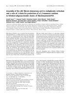
Figure 1.1: Principle of upstream transmission in an IMDD WDM RoF system.
LSB: lower-frequency sideband, USB: upper-frequency sideband.
The principle of upstream transmission in an IMDD RoF system with multiple
subscribers for a loopback access network is illustrated in Fig. 1.1 and can be explained
as follows. A wavelength-division multiplexed (WDM) continuous-wave (CW) laser
seed light from the CO traverses the transmission fiber, is demultiplexed by arrayed
waveguide grating (AWG), and is fed to the intensity modulator at each RBS for up-
stream modulation. The optical field of each CW laser seed light can be modeled
as E
L
(t) = exp(j2πf
L
t), where f
L
is the laser diode frequency. The wireless radio
5
1.2 Access Networks
frequency (RF) signal received at the RBS can be modeled as
E
RF
(t) = A(t) cos(φ(t) + 2πf
0
t), (1.3)
where f
0
is the RF carrier frequency, and A(t) and φ(t) are the amplitude and phase,
respectively, of the transmitted symbol. The RF signal is level shifted with a dc bias
of A
dc
, applied through a bias-T, to avoid negative modulating values. The biased RF
signal is modulated onto the envelope of the CW laser using an intensity modulator,
generating an optical field of
E
RoF,IM
(t) = [A
dc
+ A(t) cos(φ(t) + 2πf
0
t)] exp(j2πf
L
t) (1.4)
comprising an optical carrier and two sidebands (i.e., double-sideband (DSB) modula-
tion). These modulated E
RoF,IM
(t) signals are then multiplexed in the AWG and sent
back to the CO for detection. The transmitted RF signal in each channel is recovered
at the CO by a square-law photodetection, followed by a dc block to remove dc com-
ponents. Since the wavelength of the seed light determines that of the upstream signal,
centralized wavelength management of the channels is made possible.
RSOA
LPF
Seed light
Amplified &
modulated light
HR AR
Injection
current
dc bias
RF signal
Workstations
IM signal
Injection current
Intensity
modulator
Bias-T
CW Laser
dc block
Central
office
RBS
IM signal
Photodetector
AWG
Carrier
USB LSB
Uplink
Downlink
AWG
Carrier
CW Laser
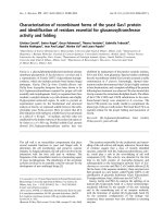
Figure 1.2: Schematic diagram of an RSOA.
The key element in a loopback network is the optical modulator at the RBS, for
which a reflective semiconductor optical amplifier (RSOA) has been favorably iden-
tified [36]. Fig. 1.2 depicts a schematic diagram of a single-port RSOA. The device
comprise an amplifying waveguide with an anti-reflector (AR) at the front end acting
as the input/output port and a high reflector (HR) at the rear end [37]. The injected
current directly modulates the gain of the RSOA and thus the intensity of the incident
6
1.2 Access Networks
light. In short, light injected into a directly-modulated RSOA is amplified, intensity
modulated, and reflected back out through the same port.
RSOAs are desirable for their (i) low cost and compact size, (ii) natural com-
bination of modulation and amplification, (iii) color-free operation (with very wide
optical bandwidth of more than 60 nm), and (iv) low noise figure [38]. RSOA being
a single-port device, unlike the two-port LiNbO
3
Mach-Zehnder modulators (MZMs)
and electroabsorption modulators, minimizes the active fiber alignments required and
has a less expensive packaging cost [36]. Inbuilt amplification gain helps overcome any
coupling loses, thus relaxing fiber alignment tolerance in RSOAs. Colorless RSOAs
allow wavelength-independent operation of the RBS, which enables dynamic wave-
length allocation to RBSs, alleviates the inventory problem, and minimizes the de-
ployment costs.
RSOA placed at the RBS and seeded by an optical carrier from the CO have
been successfully exploited to yield reliable RBSs [39–42]. However, all previously
reported RoF systems using RSOAs only accommodate RF carriers of ≤ 1 GHz, with
a maximum encoded data rate of 54 Mb/s over 20-km fiber [39, 40]. This is because
the modulation bandwidth of RSOAs is limited by the carrier life-time in the active
layer to less than 3.5 GHz [39]. It is, therefore, challenging to accommodate higher
RF carriers and data rate with the severely bandwidth-limited RSOA. Furthermore, the
chirp of RSOA will hamper the transmission reach of the system [43].
A key issue in DSB optical signals is the power penalty due to chromatic dis-
persion (CD)-induced phase shift of the two sidebands relative to the optical carrier,
which limits the transmission distance and supportable RF frequencies [44, 45]. An-
other drawback to be considered is the SNR degradation of the received signal in net-
works using centralized light sources due to crosstalk from Rayleigh backscattered
light [46].
7
1.3 Research Contributions
1.3 Research Contributions
This thesis contributes three new receiver designs for optical communications. They
are namely, two new DSP based carrier estimators in coherent receivers for long-haul
transmissions and one new optical signal processing based direct detection receiver in
IMDD RoF systems for wireless broadband access networks. The new receiver designs
and their improvement over prior art are as follows.
A novel complex-weighted decision-aided maximum-likelihood (CW-DA-ML)
carrier estimator for joint phase and frequency estimation is derived in Chapter 3. CW-
DA-ML is a decision-aided least-squares based estimator, which achieves fast carrier
acquisition, complete frequency estimation range, low SNR operability, requires no
phase unwrapping, reliably tracks time-varying frequency, and is format transparent.
Additionally, a pilot-assisted (PA) CW-DA-ML is demonstrated with low pilot over-
head. Moreover, the most desirable 4-, 8-, and 16-point constellations from the carrier
recovery perspective are identified to be QPSK, 8-QAM, and 16-QAM, respectively.
A novel low-complexity adaptive complex-weighted decision-aided (CW-DA) car-
rier estimator with a two-tap structure is derived in Chapter 4. Unlike classical estima-
tors with fixed-length filters, the effective filter length in adaptive CW-DA estimator
is automatically optimized according to SNR, ∆νT , nonlinear phase noise, and mod-
ulation format. No preset parameters are required. Furthermore, we demonstrate that
cycle slip probability is affected by the choice of filter length. Besides inheriting the
advantages of CW-DA-ML, adaptive CW-DA estimator is superior in terms of low
cycle slip probability, large nonlinear phase noise tolerance, and low complexity.
A novel optical solution, where a passive optical delay interferometer (DI) is in-
corporated before the photodetector in the direct detection receiver, is presented for
ROF receiver design in Chapter 5. DI equalizes the band-limitation of RSOA, counter-
chirps the pulse to extend transmission reach, and makes the signal immune to CD-
8