Adaptation and control state detection techniques for brain computer interfaces
Bạn đang xem bản rút gọn của tài liệu. Xem và tải ngay bản đầy đủ của tài liệu tại đây (1.45 MB, 141 trang )
Adaptation and Control State Detection
Techniques for Brain-Computer Interfaces
RAJESH CHANDRASEKHARA PANICKER
(Bachelor of Technology, University of Kerala)
A THESIS SUBMITTED
FOR T HE DEGREE OF DOCTOR OF PHIL O SOPHY
DEPARTMENT OF ELECTRICAL & COMPUTER
ENGINEERING
NATIONAL UNIVERSITY OF SINGAPORE
2011
Ackn owledgements
This thesis is a product of time and effort invested by a number of people, though
I a m mentioned to be the author. A non-exhaustive list is given below.
• My supervisors Prof . Sadasivan Puthusserypady and Dr . Sun Ying, for
providing me with all the necessary support and guidance, for being very
patient with me, and offering me a helping hand every time I stumbled. Their
wealth of experience and insight has help me tide through many difficult
situations.
• All my teachers, past and present. If I have seen a little further, it is by
standing on their shoulders.
• Ananda for help in setting up and progr amming the BCI system.
• My thesis committee members Dr. Yen and Prof. Dipti for their advice and
encouragement.
• Dr. Akash, Prof. Ashraf, Dr. Sahoo, Prof. Loh whom I worked with for the
modules I tutored, and who chipped in with help, advice and support.
ii
Acknowledgements iii
• Dr. Guan Cuntai, Yasamin, Omer, Roger, Jit Hon and Roshan for helpful
and encouraging discussions.
• Lab officers Mdm. Chia, Fook Mun, Victor, King Hock and Francis who
never hesitated to help whenever a need arose.
• All my friends who not only suppo rted me all the way, but also volunteered to
be subjects, whenever the need arose. This thesis wouldn’t have materialized
without their help.
• My dearest friends Yen, Abhilash, Vineesh, Deepu, Krishna, Kalesh, Jing,
Rahul, Huaien, Tianfang, Khanh and Vasanth.
• NUS for supporting for providing me the financial support through Research
Scholarship and Teaching Assistantship.
• Dennis Ritchie, the genius who passed away this year, for creating the won-
derful pro gramming language C, the derivative of which (C++) was used in
programming o ur BCI system.
• My grandmother, parents, sisters, brother-in-law and relatives for their un-
conditional love and support .
Summary
A brain computer interface (BCI) is an alternate channel of communication be-
tween the user and the computer, without having to go through the usual neuro-
muscular pathways. Using BCI, disabled patients can communicate with a com-
puter or control a prosthetic device just by modulating his/her brain activity. This
thesis focuses on two of the desirable capabilities of a usable and practical BCI sys-
tem - adaptation and control state detection. Adaptation is the ability of the BCI
system to adapt itself to incoming data to achieve goals such as higher information
transfer rate and lower training data requirement as compared to a non-adaptive
system. Control state detection refers to its ability to determine whether the user
is actively giving input. Such systems eliminate the need to follow the cues issued
by the computer, and allows the user to give input naturally (at will). However,
adaptation and control state detection are challenging tasks, and require the BCI
system to be able to extract more informa t ion from the data being classified.
A co-training based approach is introduced for constructing high-performance
classifiers for BCIs based on the P300 event-related potential (ERP), which were
trained from very little da ta. It uses two classifiers - Fisher’s linear discriminant
analysis (FLDA) and Bayesian linear discriminant analysis (BLDA), progressively
iv
Summary v
teaching each other to build a final classifier, which is robust and able to learn
effectively from unlabeled data. Detailed analysis of the performance is carried out
through extensive cross-validations, and it is shown that the proposed approach is
able to build high-performance classifiers from just a few minutes of labeled data
and by making efficient use of unlabeled data. The performance improvement is
shown to be even more significant in cases where the training dat a as well as the
number of trials that are averaged for detection of a character is low, both of
which are desired operational characteristics of a practical BCI system. Moreover,
the proposed method o utperforms the self-training-based approaches where the
confident predictions of a classifier is used to retrain itself.
An asynchronous BCI system combining P300 and steady-state visually evoked
potentials (SSVEP) paradigms is also proposed. The information transfer is accom-
plished using P300 ERP and the control state detection is achieved using SSVEP,
overlaid on the P300 base system. Offline and online experiments have been per-
formed with ten subjects to validate the pro posed system. It is shown t o achieve
fast and accurate control state detection without significantly compromising the
performance. Techniques for improving the performance of the proposed techniques
are also suggested.
Contents
Acknowledgements ii
Summary iv
List of Abbreviations x
List of Symbols xiii
List of Tables xvi
List of Figures xviii
1 Introduction 1
1.1 Introduction to Brain Computer Interfaces . . . . . . . . . . . . . . 1
1.2 BCI Application Scenarios and State of the Art . . . . . . . . . . . 3
1.3 Motivation and Objectives . . . . . . . . . . . . . . . . . . . . . . . 5
1.4 Thesis Contributions and Organization . . . . . . . . . . . . . . . . 6
2 Brain Computer Interface : Overview 9
vi
Contents vii
2.1 The Human Brain . . . . . . . . . . . . . . . . . . . . . . . . . . . . 9
2.1.1 Measuring brain activity . . . . . . . . . . . . . . . . . . . . 10
2.2 Electroencephalogram (EEG) . . . . . . . . . . . . . . . . . . . . . 12
2.2.1 Different types of EEG activities . . . . . . . . . . . . . . . 14
2.2.2 EEG activities used in BCIs . . . . . . . . . . . . . . . . . . 16
2.3 P300 and SSVEP based BCIs . . . . . . . . . . . . . . . . . . . . . 17
2.3.1 P300 - Overview . . . . . . . . . . . . . . . . . . . . . . . . 17
2.3.2 P300 BCIs . . . . . . . . . . . . . . . . . . . . . . . . . . . . 18
2.3.3 SSVEP - Overview . . . . . . . . . . . . . . . . . . . . . . . 21
2.3.4 Challenges in detection and classification of P300 and SSVEP 23
2.4 Preprocessing . . . . . . . . . . . . . . . . . . . . . . . . . . . . . . 24
2.5 Feature extraction . . . . . . . . . . . . . . . . . . . . . . . . . . . 26
2.5.1 Spatial feature extraction . . . . . . . . . . . . . . . . . . . 26
2.5.2 Temporal feature extraction . . . . . . . . . . . . . . . . . . 28
2.5.3 Spatio-Spectral feature extraction . . . . . . . . . . . . . . . 29
2.5.4 Power spectral density (PSD) based techniques . . . . . . . 30
2.6 Classification algorithms . . . . . . . . . . . . . . . . . . . . . . . . 30
2.6.1 Evaluation criteria for BCIs . . . . . . . . . . . . . . . . . . 34
2.7 Adaptation . . . . . . . . . . . . . . . . . . . . . . . . . . . . . . . 35
2.7.1 What to adapt . . . . . . . . . . . . . . . . . . . . . . . . . 37
2.7.2 When to adapt . . . . . . . . . . . . . . . . . . . . . . . . . 37
2.7.3 How to adapt . . . . . . . . . . . . . . . . . . . . . . . . . . 39
2.8 Control State Detection . . . . . . . . . . . . . . . . . . . . . . . . 43
3 BCI System Implement at ion 47
3.1 System Architecture . . . . . . . . . . . . . . . . . . . . . . . . . . 47
3.2 Performance Analysis of t he Basic System . . . . . . . . . . . . . . 50
3.2.1 Exp erimental setup . . . . . . . . . . . . . . . . . . . . . . . 50
Contents viii
3.2.2 Data Analysis . . . . . . . . . . . . . . . . . . . . . . . . . . 50
3.2.3 Results . . . . . . . . . . . . . . . . . . . . . . . . . . . . . . 51
4 A Two-Classifier Co-Training Approach for Adaptation in P300
BCIs 54
4.1 Introduction . . . . . . . . . . . . . . . . . . . . . . . . . . . . . . . 54
4.2 Co-Training Method . . . . . . . . . . . . . . . . . . . . . . . . . . 55
4.2.1 BLDA . . . . . . . . . . . . . . . . . . . . . . . . . . . . . . 57
4.2.2 Confidence Criterion . . . . . . . . . . . . . . . . . . . . . . 59
4.2.3 Evaluation Criteria . . . . . . . . . . . . . . . . . . . . . . . 60
4.3 Data Recording and Analysis . . . . . . . . . . . . . . . . . . . . . 61
4.3.1 Off-line Experiments . . . . . . . . . . . . . . . . . . . . . . 61
4.3.2 Cross-Validation . . . . . . . . . . . . . . . . . . . . . . . . 61
4.4 Results and Discussion . . . . . . . . . . . . . . . . . . . . . . . . . 62
4.4.1 Effect of Training Data . . . . . . . . . . . . . . . . . . . . . 63
4.4.2 Effect of Unlabeled Data . . . . . . . . . . . . . . . . . . . . 70
4.4.3 Stability . . . . . . . . . . . . . . . . . . . . . . . . . . . . . 71
4.4.4 Subjectivity . . . . . . . . . . . . . . . . . . . . . . . . . . . 73
4.4.5 Computational Complexity . . . . . . . . . . . . . . . . . . . 74
4.5 Limitations and Implementation Issues . . . . . . . . . . . . . . . . 74
4.6 Conclusions . . . . . . . . . . . . . . . . . . . . . . . . . . . . . . . 76
5 Asynchronous P300 BCI : SSVEP-Based Control State Detection 77
5.1 Introduction . . . . . . . . . . . . . . . . . . . . . . . . . . . . . . . 77
5.2 P300-SSVEP system . . . . . . . . . . . . . . . . . . . . . . . . . . 78
5.3 Exp eriments . . . . . . . . . . . . . . . . . . . . . . . . . . . . . . . 81
5.3.1 Offline Experiments . . . . . . . . . . . . . . . . . . . . . . . 81
5.3.2 Online Experiments . . . . . . . . . . . . . . . . . . . . . . . 83
Contents ix
5.4 Data Analysis . . . . . . . . . . . . . . . . . . . . . . . . . . . . . . 84
5.4.1 SSVEP Detection . . . . . . . . . . . . . . . . . . . . . . . . 84
5.4.2 P300 Classification . . . . . . . . . . . . . . . . . . . . . . . 86
5.5 Results and Discussions . . . . . . . . . . . . . . . . . . . . . . . . 87
5.5.1 Effect of SSVEP Addition . . . . . . . . . . . . . . . . . . . 87
5.5.2 Results for Offline Analysis . . . . . . . . . . . . . . . . . . 88
5.5.3 Online Results . . . . . . . . . . . . . . . . . . . . . . . . . 94
5.6 Limitations and Implementation Issues . . . . . . . . . . . . . . . . 95
5.7 Conclusions . . . . . . . . . . . . . . . . . . . . . . . . . . . . . . . 96
6 Conclusions and Future Directions 98
6.1 Adaptation . . . . . . . . . . . . . . . . . . . . . . . . . . . . . . . 99
6.2 Control State Detection . . . . . . . . . . . . . . . . . . . . . . . . 102
Bibliography 105
A Publications 121
List of Abbreviati ons
ADC Analog to Digital Converter
ALS Amyotrophic Lateral Sclerosis
AUC Area Under Curve (ROC)
BCI Brain-computer Interface
BCI Brain Computer Interface
BLDA Bayesian Linear Discriminant Analysis
BOLD Blood O xygenation Level Dependent
CA Classification Accuracy
CBLDA Co-training Bayesian Linear Discriminant Analysis
CCA Canonical Correlation Analysis
CD Cont rol state Detection
CLDA Co-training Linear Discriminant Analysis
CS Control State
CSP Common Spatial Patterns
ECoG Electrocorticogram
EEG Electroencephalogram
EOG Electrooculogram
x
List of Abbreviations xi
ERD Event Related Desynchonization
ERP Event Related Potential
ErrP Error related Potential (or Error Potential)
FFT Fast Fourier Transform
FLDA Fisher’s Linear Discriminant Analysis
fMRI functional Magnetic Resonance Imaging
FPR False Positive Rate
GA Genetic Algor it hm
GMM Gaussian Mixture Model
HDR HaemoDynamic Response
HMM Hidden Markov Model
ICA Independent Component Analysis
ICG Inter-Character Gap
IP Internet Protocol
ISI Inter-Stimulus Interval
ITR Information Transfer Rate
KNN K-Nearest Neighbour
LDA Linear Discriminant Analysis
LF-ASD Low-Frequency Asynchronous Switch Design
MEG Magnetoencephalogram
MI Motor Imagery
ML Maximum Likelihood
NCS Non-Control State
NIRS Near Infra Red Spectroscopy
PCA Principal Component Analysis
PSD Power Spectral Density
ROC Receiver-Operating Characteristic
List of Abbreviations xii
SBLDA Self-training Bayesian Linear Discriminant Analysis
SCP Slow Cortical Potentials
SFML Simple and Fast Multimedia Library
SLDA Self-t raining Linear Discriminant Analysis
S-LIC Stimulus-Locked Inter-trace Correlation
SMA Supplementary Motor Area
SMO Sequential Minimal Optimization
SNR Signal to Noise Ratio
SSVEP Steady-State Visually Evoked Potential
SVM Support Vector Machine
TCP Transmission Control Protocol
TPR True Positive Ra te
VEP Visually Evoked Potential
VMRP Voluntary Movement-Related Potentials
List o f Symbo ls
α (8-12Hz) band in EEG
β (12-30Hz) band in EEG
γ (26-100Hz) band in EEG
δ (0.5-4HZ) ba nd in EEG
θ (4-8Hz) band in EEG
µ The rhythmic activity found in α, associated with motion
F
s
Sampling rate
X
r
Raw pattern matrix
W
r
Weight vector for feature reduction
Y
r
Reduced pattern matrix
d Dimensionality o f the pattern matrix
m Dimensionality of the reduced pat tern matrix
n Tot al data points (training + test)
Σ
x
r
Correlation matrix of X
r
S Source matrix (signal produced by EEG sources)
A Mixing matrix
w
r
A column of W
r
, or W
r
when m=1
xiii
List of Symbols xiv
Y
s
Reference signal for CCA
f
st
Stimulus frequency for SSVEP elicitation
n
h
Number of harmonics considered in CCA
w
s
Projection vector for the reference signal
X Pattern matrix used for classification
y Label vector (first l elements)
x
i
s Columns of X, i
th
feature vector
y
i
s Elements of y
l Number of training da ta points
g Dimensionality of the pattern matrix for classification
w Weight vector estimated by the classifier
m Mean of all training vectors
m
k
Mean of all training vectors belonging to the k
th
class
n
c
Number of classes (2 in all our experiments)
n
k
Number of elements belonging to the k
th
class
w
i
s Elements of w
S
b
Between class scatter matrix
S
w
Within class scatter matrix
b bias term for SVM
n
R
Rounds user for detection of a character
n
s
Number of equiprobable symbols detected by a BCI
CA Classification accuracy (as fraction)
B[bits] Effective number of bits detected per symbol
X Set of all feature vectors
Y Set of all labels
L Set of labeled data
U Set of unlabeled data
List of Symbols xv
S Set of all data (labeled + unlabeled)
H Set of all mapping from X t o y
h
∗
Mapping f r om X to y
n Noise vector in BLDA
β
′
Inverse variance of no ise
D The pair (X, y)
α
′
Hyper-parameters signifying the relevance of each feature
I
′
(α
′
) g × g matrix with α
′
i
s alo ng the diagonal
C Covariance of the posterior in BLDA
m
′
Mean of the posterior in BLDA
µ
′
Mean of the predictive distribution
σ
′
Standard deviation of the predictive distribution
c
ii
Diagonal elements of C
m
′
i
Elements of m
′
tr(.) Tra ce of matrix
σ
y
i Standard deviation of averag ed scores for i
th
character detection
sgn() Signum function
n
iter
Number of cross-validation iterations
n
true
Number of iterations for which the null-hypothesis is true
σ Standard deviation of the results in cross-validation iterations
[S(f )]
f
st
Power spectral density at stimulus frequency
f
n
Narrow frequency range around f
st
f
w
Wider frequency range around f
st
List o f Tables
3.1 State of the art P300 BCIs . . . . . . . . . . . . . . . . . . . . . . . 52
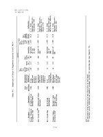
4.1 Table showing p-values f or CBLDA vs SBLDA for (300,2 ). p(Mean)
and p(Fin) are the p-values g iven by t-test (and sign test for cases
where distributions are found to be non-Gaussian through lilliefors
test) for the comparison of mean and final values respectively for
CBLDA vs SBLDA. Cases where CBLDA is significantly better than
SBLDA are highlighted. . . . . . . . . . . . . . . . . . . . . . . . . 71
5.1 Table showing P300 detection accuracies with and without SSVEP
stimuli. . . . . . . . . . . . . . . . . . . . . . . . . . . . . . . . . . . 88
5.2 Detection results for the offline experiment. The classification accu-
racy for P300 (CA), the correspo nding ITR, and the control state
detection accuracies (CD) for various number of rounds used for the
detection of a character. . . . . . . . . . . . . . . . . . . . . . . . . 93
xvi
List of Tables xvii
5.3 Detection results for the online experiment. CS and NCS are the
mean SSVEP detections for blo cks of 5 rounds, when the subject
is in control state and non-control state respectively. CD is the
block-wise detection accuracy of control state. . . . . . . . . . . . . 95
List o f Figu res
1.1 Block diagram of a BCI system. . . . . . . . . . . . . . . . . . . . . 3
2.1 Lobes of human brain (Ada pted from Fig.728, Gray’s Anatomy [1]). 10
2.2 Electrode position in the 10-20 system of recording [adapted from
(creative commons license)]). The chan-
nels used in our experiments are in g r een color. A1 and A2 (yellow)
are the reference electrodes. AFz (in black color), is the ground. . . 14
2.3 EEG signal and spectrum . . . . . . . . . . . . . . . . . . . . . . . 15
2.4 Response for target and non-target stimuli (low-pass filtered with a
cut-off frequency of 12 Hz). . . . . . . . . . . . . . . . . . . . . . . 19
2.5 The P300 speller interface. The target character during the training
phase is ‘Y’, which is yellow in color. . . . . . . . . . . . . . . . . . 20
2.6 P300 speller operation (adapt ed from [2]). . . . . . . . . . . . . . . 20
xviii
List of Figures xix
2.7 EEG spectrum with and without SSVEP. The stimulus frequency is
17.7 Hz. The higher amplitude at around 10 Hz in the absence of
SSVEP is due to higher alpha activity with the subject having eyes
closed. F
S
=256 Hz, and drift is removed by high-pass filtering with
0.5 Hz cut-off. . . . . . . . . . . . . . . . . . . . . . . . . . . . . . . 22
3.1 A user operating the BCI system . . . . . . . . . . . . . . . . . . . 48
3.2 Cross-validation results for subject 1. . . . . . . . . . . . . . . . . . 52
3.3 Cross-validation results for subject 2. . . . . . . . . . . . . . . . . . 53
3.4 Cross-validation results for subject 3. . . . . . . . . . . . . . . . . . 53
4.1 Classification accuracy vs. rounds of unlabeled data for different
percentages of classifier predictions used in self/co-training, for l=60
and n
R
= 2. P75 and P50 denotes the p-values for similar perfor-
mance of 75% and 50% of most confident classifier predictions as
compared to using 100%. . . . . . . . . . . . . . . . . . . . . . . . . 63
4.2 Classification accuracy of CBLDA, SBLDA and fully supervised
BLDA for various l (for n
R
= 2), along with the bars for ±σ (pop-
ulation standard deviations, standard error o f mean is ±0.1 × σ). . 64
4.3 Classification accuracy vs. rounds of unlabeled data for subject 1
for various l and n
R
. . . . . . . . . . . . . . . . . . . . . . . . . . . 65
4.4 Classification accuracy vs. rounds of unlabeled data for subject 2
for various l and n
R
. . . . . . . . . . . . . . . . . . . . . . . . . . . 66
4.5 Classification accuracy vs. rounds of unlabeled data for subject 3
for various l and n
R
. . . . . . . . . . . . . . . . . . . . . . . . . . . 67
4.6 Classification accuracy vs. rounds of unlabeled data for subject 4
for various l and n
R
. . . . . . . . . . . . . . . . . . . . . . . . . . . 68
4.7 Classification accuracy vs. rounds of unlabeled data for subject 5
for various l and n
R
. . . . . . . . . . . . . . . . . . . . . . . . . . . 69
List of Figures xx
4.8 Bar chart showing the bit rates for various configurations of l and n
R
.
The initial bit rate (Init.); as well as t he mean ( Mean.) and final bit
rates (Fin.) achieved are shown for each (l, n
R
) configuration and for
each subject. Please note that the error bars represent population
standard deviations (±σ), standard error of mean is ±0.1 × σ. . . . 72
5.1 Figures (a) and (b) show the two alternating states during flickering.
Rows and columns are highlighted in a pseudo-random sequence
such that each row and each column is highlighted once in every
round, as with the case of a standard P300 speller. Here, the target
character during the training phase is ‘Y’, which is yellow in color. . 80
5.2 The peak picking algor it hm. The objective function is the peak PSD
in the band enclosed by the thick lines, relative to the mean PSD in
the band enclosed by the thin lines. . . . . . . . . . . . . . . . . . . 84
5.3 FFT of the first 20 characters for Subject 1. Characters 1-10 are in
control state. . . . . . . . . . . . . . . . . . . . . . . . . . . . . . . 89
5.4 J(f
st
) for Subject 1. . . . . . . . . . . . . . . . . . . . . . . . . . . 90
5.5 ROC for the Subj ects. . . . . . . . . . . . . . . . . . . . . . . . . . 91
5.6 J(f
st
) for Subject 1 in the online experiment. . . . . . . . . . . . . 94
Chapter 1
Introduction
1.1 Introduc tion to Brain Computer Inter face s
Severe neuromuscular disorders due to trauma, brain or spinal cord injury, brain-
stem stroke, muscular dystrophies, cerebral palsy, amyotro phic lateral sclerosis
(ALS), multiple sclerosis etc. can result in peripheral motor neuron inactivity.
Such patients typically experience a locked-in syndrome, rendering them unable
to communicate their intentions or emotions in the usual manner, in spite of hav-
ing a healthy brain. They require some device which has the a bility to translate
thoughts into actions without any muscular involvement - a device which, till r e-
cently, has always been themes of folklore and science fictions. Br ain computer
interface (BCI) is all about an alternate channel of communication between the
user and the computer. A user can convey his intentions to the BCI by modu-
lating his brain activity, which is translated to useful commands for the device to
be controlled. Sitt ing in wheelcha ir, users might be able to browse the web, open
e-mails, play games, switch on lights, move a robotic arm and so o n; the technol-
ogy has a list of applications which is virtually endless. They might even help the
old and disabled to interact with ro bots, in a futur e scenario where robots will be
1
1.1 Introduction to Brain Computer Interfaces 2
used as helpers to the old-aged and disabled. Such a device will help the patient
have a better quality of life, and less dep endent on a dedicated helper. Thus BCI
hopes to provide a helping hand to patients who have permanent damage to the
neuromuscular system, which no medicine, at least with the present state of the
art, can hope to provide relief.
Apart from the utility in rehabilitation and assistive technologies, BCI also
has applications in virtual reality, gaming etc. Fo r example, a user with a head
mounted device will be able to walk in a virtual environment by using his thought
alone. BCI can also prove to be a peripheral for computer systems, taking the
place of a conventional keyboard or a mouse. The user might be able to key in the
alphabets from a keypad or dial a telephone number or move the cursor and thus
browse the web. It can take the place of a joystick in gaming systems. The same
BCI system can also be used to constantly monitor the well being of a person, thus
adding utility with little or no extra cost.
Any device capable of recording the brain activity has the potential to be used in
BCI. The most common and seemingly the only commercially viable system is the
electrical activity of the brain, recorded by electrodes placed on the scalp, known
as electroencephalogram (EEG). EEG acquisition requires only relatively simple
and portable equipment, and does no t require any invasive procedure. Various
EEG activity patterns such as P300 (evoked by a surprise stimulus), steady state
visually evoked potential
1
(SSVEP, evoked by repetitive visual stimuli), motor
imagery (MI, associated with imagined limb movements) are used in BCIs.
The block diagram of a BCI system is shown in Fig. 1.1. The EEG is recorded
using electrodes placed on the scalp. The signal is amplified using an amplifier,
and then digitized using an analog to dig it al converter (ADC). The digitized signal
is input to a computer, which processes the data to recognize activity patterns,
1
the usage steady state visual evoked potential is also popula r in the literature
1.2 BCI Application Scenarios and State of the Art 3
Signal
Acquisition
Signal
Preprocessing
Feature
Extraction
Classification
Feedback
User
Prosthetic
Device
Figure 1.1: Block diagram of a BCI system.
which are interpreted as useful commands. The computer also produces required
stimuli if the activity pattern needs to be evoked (which is the case for P300 and
SSVEP), or cues suggesting the user to start giving an input if the activity pattern
is sp ontaneous (such as motor imagery). The use of BCI system requires a training
phase. During the training, the infor ma tion is fed back to the user as a visual (e.g:
movement of a cursor or bar on computer screen), auditory (a series of tones) or
any other easily perceptible form, to help the user learn to modulate his brain
activity so as to convey his intent. Training data is required for the computer as
well, so that algorithms for processing and classification can be optimized for the
user.
1.2 BCI Application Scenarios and State of the
Art
Over the past decade, the BCI technology has grown leaps and bounds and t hou-
sands of BCI related publications have appeared in this period. Ultimately, the
technologies have to be incorporated into usable products. Commercial products
1.2 BCI Application Scenarios and State of the Art 4
from brands such as Emotiv, Neurosky etc. are available in the market. These
companies provide their software development kits as a framework for developers
to come up with interesting applications. There are a few free BCI frameworks such
as BCI2000 a nd OpenVibe ava ilable in open domain mostly aimed at researchers in
the field. To validate BCI feature extraction and classification methods, BCI com-
petitions were held in 2002, 2003, 2005 and 2008, with winning entries published in
special issues on IEEE Transactions on Biomedical Engineering and Transactions
on Neural Systems and Rehabilita t ion Engineering.
The most common application of BCIs is the speller, usually based on either
P300 or SSVEP. A speller usually has a virtual keyboard arranged as a matrix,
with keys depending on the application (6×6 alphabetic virtual keyboard being
the most popular). The rows and columns are highlighted in a pseudo-random
sequence (f or P300) or using different fr equencies / phases (for SSVEP systems).
For the P30 0 BCI, when the row or column containing character the user wants
to input is highlighted, a P300 response is produced. This can be used to find the
row and column containing the character, and hence the character itself. However,
some groups have proved that flashing of individual buttons might be better than
the row/column paradigm [3, 4]. For SSVEP, individual buttons have to flicker at
different frequncies and hence the number of characters that can be used is limited.
Another variant of the row-column paradigm is the Hex-O-Speller [5 ] intro-
duced by Blankertz et al. of the Berlin BCI group. The Hex-O-Speller selects
the character the user desires as a two- step process. First, it selects one of the 6
hexagons, which contains the desired character. The second step is to select t he
desired character out of the 6 selected characters. This interface was presented at
the world’s largest IT fair - CeBIT 2006, achieves very good accuracy and can be
implemented using any potential offering a 2-state control (such as motor imagery
or P300).
1.3 Motivation and Objectives 5
Bayliss and Ballard [6] have created P300 based systems usable for navigating in
a virtual world. Several other groups have published results on using BCI systems
for virtual r eality and gaming. Bin et al. have developed a BCI system which
allows the user to control a virtual helicopter continuously in a 3-D world through
intelligent control strategies using non-invasive BCI systems [7]. These show that
non-invasive BCIs can achieve a level of control which was previously thought to
be infeasible.
A high-performance 2-D cursor contr ol combining the µ and β rhythms with
P300 and motor imagery was demonstrated by Guan et al. [8]. Another popular
application of BCI is in wheelchair, as it is likely that the main target beneficiaries
of BCIs are wheelchair bound patients. There have been several studies focusing
on the usability and performance of such BCIs [9,10]. Recently, a hybrid BCI with
a lot of desirable features have been proposed by Allison et al. [11].
As the world is moving to an era of mobile and ha nd-held devices, and with
technological convergence, there has been a recent interest in incorporating BCI
systems into mobile/embedded platforms [12] [13] [14].
1.3 Motivation and Objectives
Since extracting useful info rmation from EEG is difficult, EEG based BCI systems
had not been getting much attention till the last decade. However, research in this
topic has geared up during the past few years, and the technology has seen tremen-
dous improvements. The development of a BCI system is highly multidisciplinary,
requiring inputs from neurology, electrophysiology, psychology, instrumentation,
signal processing, pattern recognitio n, and computer science.
The goal of all r esearch is to devise faster, more accurate and easier to use
BCI systems, with a variety of applications; symbolizing the victory of brain over
muscles. The success o f a BCI system depends on how effectively the EEG patterns