Analysis, design and optimization of offshore power system network
Bạn đang xem bản rút gọn của tài liệu. Xem và tải ngay bản đầy đủ của tài liệu tại đây (3.09 MB, 210 trang )
ANALYSIS, DESIGN AND OPTIMIZATION OF
OFFSHORE POWER SYSTEM NETWORK
PARIKSHIT YADAV
NATIONAL UNIVERSITY OF SINGAPORE
2013
ANALYSIS, DESIGN AND OPTIMIZATION OF
OFFSHORE POWER SYSTEM NETWORK
PARIKSHIT YADAV
(B.Tech (Hons.), MNIT, Jaipur, INDIA)
A THESIS SUBMITTED FOR THE DEGREE OF
DOCTOR OF PHILOSOPHY
DEPARTMENT OF ELECTRICAL AND COMPUTER
ENGINEERING
NATIONAL UNIVERSITY OF SINGAPORE
2013
DECLARATION
I hereby
declare
that this
thesis is my original
work
and
it has
been
written by me
in its
entirety.
I
have duly
acknowledged
all
the
sourees
of information
which have been used
in the
thesis.
'I ,
This
thesis
has also not been submitted
for any degree
in any
university
previously.
PARIKSHIT:YADAV
28th
March,2013
iv
CONTENTS
SUMMARY vii
ACKNOWLEDGEMENTS xi
LIST OF FIGURES xii
LIST OF TABLES xvi
CHAPTER 1. INTRODUCTION 1
1.1 Background 1
1.2 Diesel Electric Propulsion System 2
1.3 Marine Control Structure 3
1.4 Case Study of the Marine Vessel 5
1.5 Motivation and Problem Statement 7
1.6 Contribution of the Thesis 17
1.7 Overview of the Thesis 20
CHAPTER 2. AN INTELLIGENT TUNED HARMONY SEARCH ALGORITHM
FOR OPTIMIZATION 23
2.1 Introduction 23
2.2 Harmony Search and Other Variants 24
2.2.1 Harmony Search Algorithm 24
2.2.2 Harmony Search Variants 28
2.3 Proposed Method 33
2.4 Comparison with other sub-population based algorithms 41
2.5 Impact of control parameters variation on the performance of ITHS 43
2.6 Results and Discussion 53
2.6.1 Experimental study on function optimization 53
2.6.2 Computational Results 54
2.6.3 Case 1: Typical Benchmark Problems 55
2.6.4 Case 2: Shifted, Shifted Rotated and Hybrid Composite Benchmark Problems. 64
2.6.5 Case 3: Scalability study 64
2.7 Conclusions 69
CHAPTER 3. OPTIMAL SCHEDULING OF THE DIESEL GENERATORS IN
SEMI-SUBMERSIBLE OIL RIG PLATFORMS 71
v
3.1 Introduction 71
3.2 The Practical Oil Rig 73
3.3 Modeling of specific fuel consumption 73
3.4 Optimization problem formulation 77
3.5 Results and discussions 79
3.5.1 Case-I: Diesel generators with equal rating 80
3.5.2 Case-II: Diesel generators with Unequal rating 85
3.5.3 Diversity of the solution 88
3.6 Conclusion 89
CHAPTER 4. OPTIMAL THRUST ALLOCATION FOR SEMI-SUBMERSIBLE
OIL RIG PLATFORMS 90
4.1 Introduction 90
4.2 3-DOF Thrust Allocation 91
4.3 Lagrange Multiplier Optimization Method 97
4.4 Optimization Problem Formulation 100
4.5 Constraint Handling Using Superiority of Feasible Solutions 101
4.6 The Practical Oil Rig Platform 103
4.7 Results and Discussion 107
4.8 Conclusion 115
CHAPTER 5. ENERGY-EFFICIENT THRUST ALLOCATION FOR SEMI-
SUBMERSIBLE OIL RIG PLATFORMS 116
5.1 Introduction 116
5.2 Modeling of Power Consumption of the Electrical Propulsion System 117
5.2.1 Loss Model of Induction Motor 119
5.2.2 Loss Model of 3L-NPC Inverter 122
5.2.3 Loss Model of 12 Pulse Rectifier 125
Where, is the output power of the motor. is the total loss across the
induction motor. is the total losses in a 3L- NPC inverter.
is the forward diode loss.id the dc link voltage. 125
5.2.4 Loss Model of Phase Shifting Transformer 125
5.3 Optimization Problem Formulation 128
5.4 Results and Discussions 131
5.5 Conclusions 142
vi
CHAPTER 6. VOLTAGE HARMONIC DISTORTION COMPLIANT ENERGY-
EFFICIENT THRUST ALLOCATION FOR SEMI-SUBMERSIBLE OIL RIG
PLATFORMS USING AN INTELLIGENTLY TUNED HARMONY SEARCH
ALGORITHM 143
6.1 Introduction 143
6.2 Modeling of the Voltage Harmonic Distortion in the Electrical Propulsion System
144
6.3 Analysis of Harmonic Cancellation in a Quasi-24 Pulse Rectifier System 149
6.4 Voltage Harmonic Distortion Compliant Energy-Efficient Thrust Allocation
Approach 153
6.4.1 Objective Function 154
6.4.2 Equality Constraints 157
6.4.3 Variable Bounds 158
6.4.4 Inequality Constraints 161
6.4.5 Formulated Optimization Problem 161
6.5 Results and Discussions 163
6.6 Conclusions 171
CHAPTER 7. CONCLUSIONS AND FUTURE WORK 172
7.1 Conclusions 172
7.2 Future work 175
LIST OF PUBLICATIONS 178
BIBLIOGRAPHY 180
vii
SUMMARY
The rise in greenhouse gas emissions has forced the industries to rethink and change their
operating philosophy and strategies to reduce the impact on the environment by adopting
greener practices and technologies. International Maritime Organization (IMO) has
envisioned eliminating or reducing to the barest minimum, all the adverse environmental
impacts from the ships. The stringent emission legislation and the price of fuel oil has
increased the demand for safer, secure and energy efficient marine vessels. The main
objective of this thesis is to find solutions, which can significantly reduce emissions,
enhance the efficiency and safety of marine vessels. In this thesis, Keppel’s B280 Semi-
submersible oil rig platform is considered as the case study of the marine vessel.
Optimization plays an important role in finding solutions to achieve "SAFE, SECURE
AND EFFICIENT SHIPPING ON CLEANER OCEANS". The problem of reducing
emissions, enhancing the efficiency and safety of marine vessels is formulated as non-
convex optimization problems. The formulated non-convex optimization problems are hard
to solve using iterative numerical optimization methods such as Newton's method,
Sequential Quadratic Programming (SQP), Gradient descent etc. The iterative numerical
optimization methods are very fast and need less computational time, however, these
methods are highly sensitive to starting points and frequently converge to a local optimum
solution or diverge altogether. Metaheuristic algorithms eradicate some of the afore-
mentioned difficulties and are quickly replacing the classical methods in solving practical
problems. During the last decades, several metaheuristic algorithms have been proposed.
However, the performance and efficiency of most of the metaheuristic algorithms depend
on the extent of balance between diversification and intensification during the course of the
search. Proper balance between these two characteristics results in enhanced performance
viii
of the algorithm. In order to overcome this problem, a robust and self-tuned algorithm must
be developed which is almost-parameter-free search algorithm and converges very quickly,
and needs lower iterations.
In this thesis, a new variant of the Harmony Search (HS) algorithm is proposed that
maintains a proper balance between diversification and intensification throughout the
search process by automatically selecting the proper pitch adjustment strategy based on its
Harmony Memory. The performance of the proposed Intelligent Tuned Harmony Search
(ITHS) algorithm is investigated and compared with eight state-of-the-art HS variants over
17 benchmark functions. Furthermore, to investigate the robustness of the proposed
algorithm at higher dimensions, a scalability study is also performed. Finally, the numerical
results obtained reflect the superiority of the proposed ITHS algorithm in terms of accuracy,
convergence speed, and robustness when compared with other state-of-the-art HS variants.
The developed optimization problem is used to find the solutions of different formulated
optimization problems.
The next objective is to develop solutions to reduce emissions, enhance efficiency and
safety of marine vessels. To exploit the opportunity to save fuel and maintenance costs, the
multiple power generating components must be operated as optimal as possible for every
load demand. The first essential task for optimal scheduling of the generators task is to
develop an accurate model of the specific fuel consumption curve. In this thesis, the specific
fuel consumption curve is modeled using cubic spline interpolation. The specific fuel
consumption curve is used to formulate the constrained optimization problem. The
objective of the formulated optimization problem is to optimally schedule the diesel
generators to ensure minimum fuel consumption for different loading conditions. The
formulated optimization problem is solved using ITHS algorithm.
ix
The bulk of the power consumption of the marine vessel is dependent on the thruster
propulsion load. Therefore, the power demanded for propulsion must be optimized to
improve the efficiency of the vessel. The power demanded by the propulsion system is
mainly governed by the Dynamic Positioning (DP) system. The main purpose of a
positioning control system is to make sure that a vessel maintains a specified position and
compass heading, unaffected by the disturbances acting on it. In DP system, the thrust
allocator is used to distribute the desired generalized forces computed by the motion
controller among the thrusters. However, in order to ensure safe operation of the vessel
despite the thruster failure, the vessel is equipped with redundant thruster configuration and
therefore is over-actuated as per the guidelines of IMO (International Maritime
Organization) MSC (Maritime Safety Committee) Circ.645 and IMCA (International
Marine Contractors Association) M 103. For over-actuated vessels, the solution to the
thrust allocation problem can be found by formulating it as an optimization problem. In this
thesis, the over-actuated control allocation problem is solved with an objective to minimize
power consumption. The developed ITHS algorithm is used for solving the non-convex
thrust allocation problem. The optimal thruster allocation using ITHS reduces power
consumption of the rig as compared to other optimization algorithms.
The power consumed by the marine vessel depends on the thrust generated by the thrusters
and the efficiency of the electrical propulsion system controlling the thrusters. However,
most of the optimization based approaches only focus on minimizing the power demanded
by the thrusters and ignore the efficiency of the electrical propulsion system. However,
during lower demand (calm weather conditions), if all thrusters are operating
simultaneously then the electrical propulsion system of the thrusters are lightly loaded and
operate in inefficient regions. Therefore, one should distribute the maximum load amongst
some of the thrusters while keeping others idle. In this thesis, an energy-efficient thrust
x
allocation approach is proposed and formulated as an optimization problem, with an
objective to minimize the total power consumption by ensuring that the electrical
propulsion system operates in the efficient region. The optimal thruster allocation using
ITHS reduces the power consumption of the rig as compared to other optimization
algorithms. Furthermore, the total power consumption for energy-efficient thrust allocation
approach is lower as compared to conventional thrust allocation approach for all the
considered algorithms. It proves that the proposed approach is effective in reducing the
power consumption of the semi-submersible oil rig platform.
Another important aspect that is of concern is the harmonic distortions in marine vessels.
Harmonic distortion in the electrical power system is an important factor for safe and
reliable operation of the marine vessels, as it adversely affects the electric and electronic
sub-systems. Therefore, marine regulating bodies have imposed stringent limits on voltage
total harmonic distortion and individual harmonic distortion at the point of common
coupling. In this thesis, a Voltage Harmonic compliant Energy-Efficient thrust allocation
problem is formulated to enhance the efficiency and also ensure that the electric propulsion
system meets the harmonic limits as per marine standards. The formulated optimization
problem is solved using the ITHS algorithm. After meeting the harmonic limits, the total
power consumption for the oil rig platform using ITHS algorithm is lower compared to
other optimization algorithms. The major advantage of the proposed approaches is that,
there is no need of additional hardware integration and the proposed approaches can be
integrated in the existing system by just changing the algorithms of the DP software.
Therefore, the proposed solutions can be applied to both new and old vessels.
xi
ACKNOWLEDGEMENTS
I wish to record my deepest sense of gratitude to my research supervisor, Assoc. Prof.
Sanjib Kumar Panda, who has introduced the present area of work and guided in this work.
Assoc. Prof. Sanjib Kumar Panda has been a source of incessant encouragement and patient
guidance throughout the thesis work. I am extremely grateful and obliged to Assoc. Prof.
Chang Che-Sau for his intellectual innovative and highly investigative guidance in the
thesis work.
I am highly obliged to Dr. Rajesh Kumar for his constant support and encouragement
during my research work. He has always been a source of inspiration, motivation and
scholarly guidance. I shall always remember the lively and rewarding moments I had during
my research work. I would like to express special thanks to Dr. Sanjib Kumar Sahoo and
Dr. Akshay Kumar Rathore for their valuable advice in the area of electrical machines and
power electronics. I would also like to thank Assoc. Prof. Y. C. Liang, Assist. Prof. Akshay
K. Rathore and Assist. Prof. Panida Jirutitijaroen for their guidance as PhD Thesis
Committee Members.
I wish to express my gratitude to Mr. Y. C. Woo, and Mr. M. Chandra of Electrical
machines and Drives lab, NUS, for selfless support. I acknowledge the help and
encouragements from colleagues and friends in Electrical Machine and Drives Laboratory,
Energy Management and Microgrid Laboratory and Centre for Power Electronics. Special
thanks to Bhuneshwar Prasad who offered his selfless help and support during the course
of writing my thesis.
Finally, with bowed head, I convey my regards to my parents Shri. Jagadish Chand Yadav
and Smt. Susheela Yadav who raised me with a love of science and supported me in all my
pursuits. I would also like to thank my sister Rekha Yadav and brother Rishi Yadav for
their love and affection. Last but not the least, I would like to thank my loving, supportive,
encouraging, and patient wife Renu Singh, for her unconditional love and support during
the entire course of my doctoral studies.
xii
LIST OF FIGURES
1.1 Overview of an automatic ship control system with a high level
controller………………………………………………………………………… 4
1.2 SLD of the electrical propulsion system of the Keppel’s B280………………… 6
1.3 Thruster layout of Keppel’s B280 and corresponding dimensions 6
2.1 Pitch adjustment mechanism for the 2-D multimodal problem
with variables X1 and X2 in GHS, where HMS = 5,
HMCR =1 and PAR = 1 30
2.2 Pitch adjustment mechanism for the 2-D multimodal problem
with variables X1 and X2 Fig. 2.2in SAHS, where HMS = 5,
HMCR =1 and PAR =1…………………… ………………………………… 32
2.3 Variation of the size of Group A in ITHS with iterations……………………… 38
2.4 Variation in the difference of HMmean and HMbest in
ITHS with iterations………………………………………………………….… 39
2.5 Variation of the Mean Fitness Value with change in
HMS and HMCR for Sphere’s Function…………………………… 45
2.6 Variation of the Mean Fitness Value with change in
HMS and HMCR for Schwefel’s Problem 2.22……………………………… 46
2.7 Variation of the Mean Fitness Value with change in
HMS and HMCR for Rosenbrock Function…………………………………… 46
2.8 Variation of the Mean Fitness Value with change in
HMS and HMCR for Rotated Hyper- Ellipsoid Function………… 47
2.9 Variation of the Mean Fitness Value with change in
HMS and HMCR for Generalised Schwefel’s 2.26 Problem……… 47
2.10 Variation of the Mean Fitness Value with change in
HMS and HMCR for Rastrigin Function…………………………………… 48
2.11 Variation of the Mean Fitness Value with change in
HMS and HMCR for Ackley’s Function…………………………………… 48
2.12 Variation of the Mean Fitness Value with change in
HMS and HMCR for Griewank Function………………………… 49
2.13 Variation of the Mean Fitness Value with change in
HMS and HMCR for Six-Hump Camel-Back Problem…………………………49
xiii
2.14 Convergence of Sphere Function for 30 dimensions…………………………….58
2.15 Convergence of Schwefel’s Problem 2.22 for 30 dimensions………………… 58
2.16 Convergence of Schwefel’s Problem 2.22 for 30 dimensions………………… 59
2.17 Convergence of Rosenbrock Function for 30 dimensions……………………….59
2.18 Convergence of Rotated Hyper-Ellipsoid Function
for 30 dimensions…………………………………………………… 60
2.19 Convergence of Generalised Schwefel’s 2.26 Problem
for 30 dimensions…………………………………………………… 60
2.20 Convergence of Rastrigin Function for 30 dimensions………………………… 61
2.21 Convergence of Ackley’s Function for 30 dimensions………………………… 61
2.22 Convergence of Griewank Function for 30 dimensions………………………….62
2.23 Convergence of Camel-Back Function……………………………………… 62
3.1 Single Line Diagram of Thruster system…………………………… 74
3.2 Specific Fuel Consumption of the diesel Generator at
different loads………………………………………………………… 77
3.3 Convergence of the HS, IHS and ITHS at 3 pu load…………………………… 81
3.4 Scheduling of the Diesel Generators at 3 pu load……………………………… 82
3.5 Variation of solution for different methods at 3 pu load…………………………86
4.1 Sign conventions used for thruster allocation……………………… 91
4.2 Reference frame of i
th
actuator for calculation of
forces and moment…………………………………………………… 93
4.3 Shaded region represents the ATR of i
th
and (i+1)
th
thrusters………………… 96
4.4 Actuator layout of Keppel’s B280 and corresponding
dimensions with respect to origin at main drill well)………………………… 104
4.5 % Error in Power calculated using P1=0.176 |T |1.5
and P2=0.011T2……………………………………………………………… 105
4.6 Shaded region represents the ATR for the
corresponding thrusters……………………………………………………… 106
xiv
4.7 The commanded (a) longitudinal resultant thrust (FX ),
(b)lateral resultant thrust (FY ), and (c) moment
(MZ) at 50 time steps………………………………………………………… 109
4.8 Convergence of ITHS, IHS, HS and GA for
demanded FX =49.959kN , FY = -60.481 kN and MZ =-63787 kN……… 110
4.9 (a) Delivered thrust forces and (b) corresponding azimuth
angles for Thruster 1……………………………………………………… 111
4.10 (a) Delivered thrust forces and (b) corresponding azimuth
angles for Thruster 3……………………………………………… 112
4.11 The Total power consumption during thruster allocation
for 50 time steps for ITHS, IHS, HS, GA
and Mincon algorithm…………………………………………………… 114
5.1 Electrical Propulsion System for a single thruster motor…………….…………118
5.2 Harmonic Losses (kW) at different loads………………………… 122
5.3 Single phase of Siemens GM150 3L-NPC Inverter…………………….…… 122
5.4 Comparison of measured and modeled displacement
power factor (cos
)……………………………………………………… 126
5.5 Comparison of measured and modeled efficiency of
the electrical propulsion system………………………………………….…… 128
5.6 The commanded (a)longitudinal resultant thrust (FX),
(b)lateral resultant thrust (FY), and (c) moment
(MZ) at 50 time steps………………………………………………………… 134
5.7 (a) Thrust forces and (b) corresponding azimuth
angles for Thruster 1…………………………………………………….………135
5.8 (a) Thrust forces and (b) corresponding azimuth
angles for Thruster 3………………………………………………………… 136
5.9 Total power consumption of the oil rig platform during
thruster allocation for 50 time steps with (a) energy-efficient
thrust allocation and (b) conventional thrust allocation…………………… 137
5.10 (a) Delivered thrust forces and (b) corresponding azimuth
angles for Thruster 1……………………………………………… 140
6.1 Electrical Propulsion System for a single thruster motor……………… 145
6.2 Winding connections for a Dd11.d0. vector group…………………… 146
xv
6.3 Equivalent electrical circuit of DZZ transformer………………… 147
6.4 Variation of
with change in the loading of T1 and T2………………… 153
6.5 Comparison of measured and modeled efficiency of the
electrical propulsion system…………………………………………………….156
6.6 Shaded region of the circle represents the ATR of ith and
(i+1)th thrusters……………………………………………………………… 160
6.7 The commanded (a)longitudinal resultant thrust (FX),
(b)lateral resultant thrust (FY), and (c) moment
(MZ) at 50 time steps………………………………………………………… 164
6.8
for Energy Efficient Thrust Allocation (EETA) and
Harmonic compliant Energy- Efficient Thrust allocation
(HEETA) using (a) ITHS, (b) IHS, (c) HS, and (d) GA……………………… 167
6.9 Total power consumption of the oil rig platform during
thruster allocation for 50 time steps with (a) Energy Efficient
Thrust Allocation (b) Harmonic compliant Energy-Efficient
Thrust allocation…………………………………………………… 169
7.1 SLD of the electrical propulsion system of the Keppel’s B280……………… 177
xvi
LIST OF TABLES
2.1: Procedure of Group Formation……………………….………………………….34
2.2: Formation of group using ITHS for a 5-dimension problem…………………….39
2.3: Pseudo code for ITHS algorithm…………………………………………………40
2.4: Benchmark Problems…………………………………………………… 44
2.5: Variation of the best fitness value with change in HMS and
HMCR for Sphere function for 30 dimensions 50
2.6: Variation of the best fitness value with change in HMS and
HMCR for Schwefel’s 2.22 problem function for 30 dimensions 50
2.7: Variation of the best fitness value with change in HMS and
HMCR for Rosenbrock function for 30 dimensions 50
2.8: Variation of the best fitness value with change in HMS and
HMCR for Rotated hyper-ellipsoid function for 30 dimensions 51
2.9: Variation of the best fitness value with change in HMS and
HMCR for Generalised Schwefel’s 2.26 problem for 30 dimensions 51
2.10: Variation of the best fitness value with change in HMS and
HMCR for Rastring function for 30 dimensions 51
2.11: Variation of the best fitness value with change in HMS and
HMCR for Ackley’s function for 30 dimensions 52
2.12: Variation of the best fitness value with change in HMS and
HMCR for Griewank function for 30 dimensions 52
2.13: Variation of the best fitness value with change in HMS and
HMCR for Six-hump Camel-back problem 52
2.14: Shifted and Shifted Rotated Benchmark Problems 57
2.15: The t-test results of comparing ITHS with the other HS
algorithms 57
xvii
2.16: Mean and Standard Deviation (SD) of the benchmark function optimization
Results (N=30) 65
2.17: Number of successful runs, mean number and standard deviation of iterations,
required to converge to the threshold error limit over the successful runs for
functions f
1
to f
9
66
2.18: Mean and Standard Deviation (SD) of error for shifted and shifted rotated
benchmark functions (f
10
to f
17
) 67
2.19: Mean and Standard Deviation (SD) of error for the benchmark functions
(N=50)……………………… 68
3.1: SFC of the Diesel Generator at different loads 75
3.2: Norms of the residuals for various methods 75
3.3: Initial Harmony Memory Matrix for the formulated problem
for 3 pu load 83
3.4: Final Harmony Memory Matrix for the formulated problem
for 3 pu load 84
3.5: Total fuel consumption rate of the generators at different
loads 84
3.6: Comparision of the best solution for 0.5 pu load for Case (I) 85
3.7: Comparision of the best solution for 2.5 pu load for Case (II) 85
3.8: Total fuel consumption rate of the generators at different
loads 86
3.9: Comparision of different optimization techniques for
3 pu load (50 trials) 88
3.10: Comparision of different optimization techniques for
2.5 pu load (50 trials) 88
4.1: Total Power Consumption of the oil rig platform for the entire load
cycle 115
5.1: Parameters of the induction motor 119
xviii
5.2: Parameters of EUPEC 3.3 kV/1200 A NPT-IGBT
(FZ1200R33KF2)…………………………………………………………… 124
5.3: Loading of different thrusters for both the switching sequences………… 133
5.4: Total Power Consumption of the oil rig platform for the entire
load cycle …………………………………………………………………… 138
6.1: Specifications of the phase shifting transformer ………………………… 147
6.2: Parameters for the DZZ transformer ………………………………………… 148
6.3: Parameters of the induction motor ………………………………………….…148
6.4: Total Power Consumption of the oil rig platform for the
entire load cycle……………………………………………………………… 170
1
CHAPTER 1. INTRODUCTION
1.1 Background
Shipping plays a very important and vital role in today's global society. Seaborne transport
services the global demand for food, energy, raw materials and finished products. Apart
from trade and transportation, various other tasks are performed by special ships. These
include offshore service activities, infrastructure development (such as cable laying, pipe
laying and dredging), fishing, exploration and research, towing services, etc [1]. Therefore,
shipping is truly the lynchpin of the global economy. Due to close connection to trade,
international shipping also plays a vital role in facilitation of trade as the most cost-effective
means of transport.
Shipping is responsible for transporting almost 90% of world trade which has doubled in
the past 25 years and corresponds to 3.3% of the global CO
2
emissions. International
Maritime Organization (IMO) projects that CO
2
emissions from international maritime
activity are expected to rise by10-26% by 2020 and by 126-218 % by 2050 [1, 2]. The
demand for global shipping brings with it a host of environmental related problems and
therefore, shipping emissions have been recognized as a growing problem for
environmental policy makers [3]. Another important concern for shipping industry is safe
and reliable operation of the marine vessels. During, the last few decades, the concept of
diesel-electric propulsion has emerged as a key technology in providing "SAFE, SECURE
AND EFFICIENT SHIPPING ON CLEANER OCEANS".
Diesel-electric propulsion decouples the speed of the diesel engine from that of the
propeller and offers the possibility to operate the diesel engines at their optimum
operational point, resulting in lower emissions and lower fuel consumption as compared to
conventional diesel-engine based direct drive system. In addition, diesel-electric propulsion
2
provides other benefits, such as increased safety, survivability, maneuverability, precise
and smooth speed control, reduced machinery space, low operational and maintenance
costs, increased design flexibility and capability to reduce noise [4].
1.2 Diesel Electric Propulsion System
The diesel-electric propulsion system is powered via an on-board power pool consisting
typically of 6-8 diesel generators. In a diesel-electric propulsion system, the diesel engines
are normally medium to high-speed engines. The diesel generators are connected to the
switchboard to form the high voltage busbar. The switchboard is usually distributed or split
in two, three, or four sections, in order to obtain the redundancy requirements of the vessel
[5, 6]. As per the application guidelines from NORSOK (Norsk Sokkels
Konkuranseposisjon), the switchboard voltage levels for the main distribution system are
as follows :
- 11kV: Medium voltage generation and distribution. Should be used when total installed
generator capacity exceeds 20MW. Should be used for motors from 400kW and above.
- 6.6kV: Medium voltage generation and distribution. Should be used when total installed
generator capacity is between 4-20MW. Should be used for motors from 300kW and above.
- 690V: Low voltage generation and distribution. Should be used when total installed
generator capacity is below 4MW. Should be used for consumers below 400kW and as
primary voltage for converters for drilling motors.
- For utility distribution lower voltage is used, e.g. 400/230V.
The electric power from the switchboard is transferred into different forms of energy. The
majority of the power onboard is used for propulsion. The electrical motors are used to
convert electrical energy into mechanical energy used by propellers. Induction motors are
3
the most commonly used for propulsion. However, synchronous motors may also be used
for high power applications. The thrust produced is controlled either by constant speed and
controllable pitch propeller design, variable speed fixed pitch propeller design, or in rare
cases with a combination of speed and pitch control. Variable speed fixed pitch propeller
design has significantly simpler mechanical underwater construction with reduced low-
thrust losses compared to controllable pitch propeller [6]. In case of variable speed fixed
pitch propeller design, the thrust is controlled by varying the speed of the propeller using
variable frequency drive.
1.3 Marine Control Structure
Marine control system has been of special interest since last century. The various
complexities and coupled behavior demands for automatic control system for marine
vessels. Automatic control system is widely used for controlling the heading, heave control,
way-point tracking control, fin and rudder-roll damping, dynamic positioning (DP),
thruster assisted position mooring (PM) etc. [4].
Increasing industrial and social development on a global scale has led to unprecedented
demand for energy, the vast majority of which continues to be met through the exploitation
of the world’s finite reserves of fossil fuels. This motivates exploration and exploitation at
continuously increasing water depths. For deeper depths conventional mooring systems,
like a jack-up barge or an anchored rig, structure cannot be used rather DP system and
thruster assisted position mooring system are used to keep the marine vessel in the fixed
position. DP system automatically controls the position and heading of the marine vessel
subjected to environmental and external forces, using large rating azimuth thrusters fitted
at its pontoon level [7, 8]. DP and PM systems are used on different types of vessels,
ranging from shuttle tankers, semi-submersibles, offshore service vessels, construction
4
vessels and cruise vessels, etc. [9]. The block diagram of a control system of a typical
marine vessel is shown in Fig.1.1.
Wind, Wave
and Current
DP Controller
Vessel
Position
Intelligent
Thrust Allocator
Thruster Drive
G
G
Intelligent Power
Management
System
Power
Plant
Optimum
thrust
command
Torque
(T
p
)
Total Thrust
Demanded
Reference
Setpoint
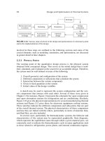
Fig.1.1. Overview of an automatic ship control system with a high level controller.
The reference set point may be either to keep the vessel in the fixed position with a fixed
heading or follow a particular trajectory (Tracking control). The vessel is subjected to
different environmental disturbances and these disturbances constitute of disturbances due
to waves, current and wind. The environmental disturbances deviate the vessel from the
desired set point. The vessels position is measured or estimated using different kinds of
sensors and algorithms and sent to the DP controller. The DP controller produces desired
surge force
, sway force
and yaw moment
required to keep the vessel at
the desired set point. The thrust allocator needs to determine the magnitude and direction
of the thrust required for each thruster to create a force and moment equilibrium. However,
5
there exist multiple solutions for the thrust-allocation problem because, the marine vessels
are over-actuated as per the guidelines of guidelines of IMO MSC Circ.645 and IMCA M
103 [10, 11]. Therefore, the solution to the thrust allocation problem can be found by
formulating it as an optimization problem, with an objective to minimize power
consumption, drag, tear/wear and other costs related the control variables, subjected to the
constraints such as thruster position constraints and other operational constraints [12, 13].
The solution of the thrust allocation algorithm is fed as reference input to the thruster drives.
The thruster drive ensures that the actuators produce the desired thrust. The power required
by the thruster drives is demanded from the marine power plant. A typical marine vessel is
powered via an on-board power pool consisting typically of 6-8 diesel generators.
Therefore, power management system is required for optimal scheduling of the generators.
The thrust allocator and power management system play and significant role in the control
of the marine vessel.
1.4 Case Study of the Marine Vessel
In this thesis, Keppel’s B280 Semi-submersible oil rig platform is considered as the case
study of the marine vessel. The oil rig is powered by a pool of eight Wärtsilä 16V26A diesel
generators each of 4960 kW power rating. The eight generators are connected in ring
configuration to form the 11 kV busbar. The 11 kV busbar supplies the load to the eight
thruster motors, located at the pontoon level of the oil rig platform and other auxiliary loads
[14]. Fig. 1.2 shows the schematic of the main power installations in a Keppel B280 semi-
submersible oil rig platform with electrical propulsion in a Single Line Diagram (SLD)
[15]. The vessel is a four column stabilized semi-submersible oil rig platform. Four
rectangular shaped stability columns, and two pontoons provide the buoyancy. The thruster
layout of the oil rig platform is shown in Fig. 1.3.
6
11kV Busbar
AC/DC
DC/AC
D
Z Z
AC/DC
DC/AC
D
Z Z
AC/DC
DC/AC
D
Z Z
AC/DC
DC/AC
D
Z Z
AC/DC
DC/AC
D
Z Z
AC/DC
DC/AC
D
Z Z
AC/DC
DC/AC
D
Z Z
AC/DC
DC/AC
D
Z Z
11kV Busbar
Generator 8
Generator 7
Generator 1 Generator 2
Generator 5 Generator 6 Generator 4 Generator 3
T8 T7 T1 T2
T4 T3T6T5
Fig. 1.2. SLD of the electrical propulsion system of the Keppel’s B280
STARBOARD
PORT
40810mm
44749mm44741mm
25499mm
33500mm
40735mm
FORWARD
AFTERWARD
MAIN DRILL
WELL
25499mm
33500mm
T1
T2
T3
T4
T6
T5
T7
T8
Fig. 1.3. Thruster layout of Keppel’s B280 and corresponding dimensions
7
1.5 Motivation and Problem Statement
Industrial Revolution led to the use of machinery and factories for mass production with a
sole objective to enhance the productivity and profits. However, on the contrary industrial
revolution also led to multifold increase in the greenhouse gas emissions. The rise in
greenhouse gas emissions has forced the industries to rethink and change their operating
philosophy and strategies to reduce the impact on the environment by adopting greener
practices and technologies. IMO has envisioned eliminating or reducing to the barest
minimum, all the adverse environmental impacts from the ships. In addition to the strong
environmental concerns, the sky-rocketing fuel prices have changed the competitive
landscape. Over, the last ten years, the price of fuel oil has increased by six times and in
Singapore, the world’s largest bunkering port, the price of fuel oil has increased by 45 %
in the last two years [16]. The price of fuel now represents around 50% or more of vessel
operating costs. The stringent emission legislation and the price of fuel oil has increased
the demand for safer, secure and energy efficient marine vessels. In this thesis, some of
the issues identified have been related to the marine control structure which can
significantly reduce the emissions, enhance the efficiency and safety of marine vessels.
Issue 1: Optimal Scheduling of the Diesel Generators in Semi-submersible Oil
Rig Platforms
To exploit the opportunity to save fuel and maintenance costs, the multiple power
generating components must be operated as optimal as possible for every load
demand. The oil rig is powered by a pool of eight Wärtsilä 16V26A diesel
generators each of 4960 kW power rating. The load requirements of the rig are
governed by the disturbances, which are stochastic in nature and most of the time
the demanded load is less than 50% of the full load [17, 18]. Therefore, generators


