Bone marrow derived mesenchymal stem cell (BM MSC) application in articular cartilage repair 7
Bạn đang xem bản rút gọn của tài liệu. Xem và tải ngay bản đầy đủ của tài liệu tại đây (5.6 MB, 25 trang )
77!
Moreover, our results showed that the migrated cells in the cartilage defect
could increase the quality of the repaired cartilage, which is in accordance to
the previous studies by Lee et al. (208, 209). Also our results showed that
reinforcing the endogenous MSCs by harvesting and local injection to the
injured site of the cartilage could lead to a higher quality of cartilage repair as
suggested by Fong et al. (210).
In conclusion our results indicated that labeling of the cells with an optimized
concentration of the SPIO could be a useful tool to evaluate the fate of MSCs
after administration. It is possible to monitor the migration and localization of
cells using MRI, a non-invasive and repeatable technique, for in vivo
evaluation. In addition, we showed that labeled MSCs have the tendency to
move to the injured cartilage site, engraft and increase the quality of the
repaired cartilage by production of the more hyaline-like cartilage. The MSCs
also have the tendency to home in the other sources of the inflammation such
as para-patellar fat and surgical scars.
78!
Chapter 4 Simulating Injured Articular
Cartilage Environment for Mesenchymal
Stem Cell Migration Evaluation in A Three
Dimensional Microenvironment
79!
4.1 Abstract
Introduction:
Avascular nature of the articular cartilage provides only a limited capacity of
self-repair. Cell based therapy is one promising approach in the treatment of
damaged cartilage. Bone marrow (BM) derived mesenchymal stem cell (MSC)
is a good candidate because of their multipotent nature. The use of MSCs for
cartilage repair relies on the homing and engraftment of the cells to the injured
tissue. Although there is speculation that injured tissue expresses ligands and
chemotactic factors that could attract MSCs, these factors and their
mechanisms are not yet fully understood. In vitro modeling is challenging.
Microfluidic platforms can study of the cell migration in 3D environment and at
the same time provide live observation as well as time laps evaluation of the
cellular behavior. In this study I designed a microfluidic platform to observe
the injured cartilage tissue as well as MSCs at the same time. By simulating
the injured tissue environment, I could study the effect of MSC on the injured
tissue.
Purpose:
The purpose of this study is to develop a microfluidic system. The system will
be used to evaluate the migration of MSCs against the injured cartilage tissue
and to identify potential chemo-attractants for the migration. By exploring the
interaction of MSCs with cartilage tissue and the chemo-attractant factors, it
may be possible to improve current MSC therapies as well as open new
avenues for cartilage repair.
80!
Method and approach:
A 3D microfluidic system was developed by integrating a hydrogel scaffold
into a polydimethylsiloxane (PDMS) platform, so that it is possible to culture
cartilage tissue and MSCs simultaneously. The device design was evaluated
for the linear concentration gradient of chemo-attractants toward the 3D
hydrogel. Also the migration of the MSCs was examined by supplementing
the media with platelet-derived growth factor (PDGF) to validate the migration
of the cells. Uninjured and injured cartilage tissues were prepared by using an
established method. Conditioned media were prepared by culturing uninjured
and injured cartilage tissues in complete media (CM), and the migration
distance of the cells in conditioned medias and unconditioned CM were
compared. The average migration distances of MSCs toward uninjured and
injured conditioned media, and tissues were compared. RT-PCR were used to
investigate expressions of ligand genes such as CXCL10, TGFA, IGF2,
CXCL12, ANGPT1, FGF2, TGFB3, and BMP4, as well as extracellular matrix
(ECM) protein genes like COL1A1, and VTN in injured cartilage comparing to
the uninjured tissue.
Results:
The results showed that MSCs significantly migrated more (in terms of
distance) toward injured cartilage rather than uninjured cartilage. The
phenomenon was observed in the movement of cells toward the tissues as
well as the conditioned media produced by the tissues.
RT-PCR demonstrated that cartilage injury leads to an up-regulation of the
gene expressions of collagen type I A1 (COL1A1), chemokine CXC 10
(CXCL10), transforming growth factor-alpha (TGFA), insulin-like growth factor
81!
2 (IGF2), chemokine CXC 12 (CXCL12), angiopoietin 1 (ANGPT1), fibroblast
growth factor 2 (FGF2), transforming growth factor beta-3 (TGFβ3), bone
morphogenetic protein 4 (BMP4), vitronectin (VTN).
Conclusion:
As I showed in the previous chapter, injection of stem cells in the knee is a
promising method for cartilage repair. In this chapter I introduced a novel
microfluidic platform, which proved to be a flexible tool to study cell migration
for various biological applications. I confirmed that engraftment of the MSCs in
injured cartilage is an active migration and homing process and injured
cartilage encourage the migration of the MSCs toward the injury site. I also
showed that the cartilage injury up-regulate some specific chemotactic
factors, which can help to find and select a sub-population of MSCs which
show stronger response to such factors in cartilage repair. Then, on one
hand, enhancement of the homing capacity of MSC can be achieved by
modulating their response to chemotactic factors; and on the other hand,
modulation can be applied in the site of injury for example with stimulating the
target site to attract more MSCs (with releasing more signals).
It provides a well-controlled cell and tissue environment, and real time
monitoring of their interaction. Furthermore, it allows for integration of
biophysical and biochemical factors essential in mimicking physiological
conditions for cells after administration.
Key words: Mesenchymal stem cell (MSC), cell migration, microfluidic
device, cartilage, tissue culture
82!
4.2 Introduction
Cartilage injuries are one of the major causes of disabilities in the world,
resulting in substantial morbidity at a high cost for the society (211). The
avascular nature of articular cartilage provides a limited capacity of self-
repairing (185, 212, 213). Different approaches include palliative therapy
(debridement), microfracture, osteochondral mosaicplasty, and cell based
therapy (autologous chondrocyte implantation, or matrix associated cell
implantation)(29). Recently, cell based therapy such as mesenchymal stem
cells (MSCs) become one of the promising modalities in treatment of the
cartilage injuries (61, 185) and MSCs showed a significant potential for tissue
repair (185, 214, 215).
As shown in the previous chapter, the injection of MSCs in the injured
cartilage knee, could improve the quality of the repaired cartilage. Presence of
the MSCs in the injured cartilage could be due to passive localization or active
migration of the cells toward injured cartilage. Therefore, to evaluate the effect
of acute cartilage injuries on migration of MSCs, I simulated the MSCs
migration toward the injured cartilage by designing a microfluidic system.
Microfluidic platforms are capable of mimicking some of the complexities of in
vivo conditions. This device provides the opportunity to culture the stem cells
and injured tissues at the same time to observe their interactions. The
integrated 3D scaffolds between the microfluidic channels are a simple
imitation of in vivo environment that provide control of the gradient between
channels (178, 216). In addition, high quality imaging capabilities allow for
simultaneous real-time monitoring of cells give a better understanding of the
in vivo circumstances (217). Previous studies showed that microfluidic
83!
devices can be used to study the effect of the blocking agents on drug
screening of the epithelial-mesenchymal transition (EMT) phenomenon (218),
interactions of the cancer and endothelial cells (219), hepatocyte growth (220)
and cell-cell interaction in liver (221, 222), biochemical gradient-guided
cellular dynamics (223, 224) and gradient mediated migration (223), as well
as a simulation on aspects of tissue and organ function (225).
Use of MSCs for cartilage repair relies on the homing and integration of the
cells to the injured tissue. Although there are speculations that other injured
tissues express ligands and chemotactic factors that encourage homing of
cells (226-229), but to my knowledge, there is no study which has evaluated
the mechanisms of stem cells migration toward injured cartilage and the
chemotactic factors secreted by injured cartilage which leads to stem cell
migration toward injured cartilage tissue.
In this study I developed a microfluidic device to simulate the injured cartilage
tissue environment, which provides the ability of simultaneous culturing and
monitoring of uninjured cartilage tissue, injured cartilage tissue and MSCs.
Then, migration of MSCs against the injured cartilage tissue was evaluated.
Exploring the interaction of MSCs with injured cartilage tissue can open a new
avenue in future of cartilage repair strategies.
84!
4.3 Methods
On this project, I collaborated with Dr. Roger Kamm, head of BioSyM in
SMART institute, Singapore, and his group. To be able to culture the cartilage
tissue simultaneously with MSCs, I designed and produced a novel
microfluidic device. I got trained in BioSyM facilities and performed all the
device production and migration experiments to evaluate the stem cells
migration behavior in the presence of the injured and uninjured cartilage
tissues. To perform a trial on using the microfluidic device as a tool for
studying of stem cell migration, I used one of the established devices at
BioSyM. The device in figure 4.1 (A) (3-channel device) was designed to
evaluate the migration of endothelial cells and angiogenesis (220) and was
well described in a manuscript published in peer reviewed journal. I got
trained for the microfluidic production and migration assays with help of Dr.
Amir Aref, a postdoctoral fellow at BioSyM. I used the 3-channel device to
assess cell migration in the 3D scaffold of microfluidic platform and also to
optimize the best collagen polymerization concentration for MSCs. As the 3-
channel device was not designed for culturing the tissue samples, I needed to
design my own device. I prepared two different designs of microfluidic
devices. The first device was the tissue spider device as shown in figure 4.1B
and 4.1C. The tissue spider device had some limitations such as risk of cross
contamination of the chemotactic factors and the long distance between the
tissues, which increased the risk of hypoxia in the center of the collagen
channel. The second device is the current tissue 3-channel device (figure
4.1D). This device had some advantages to the previous one such as
separate channel for nutrition of each tissue and minimum risk of cross
85!
contamination of the chemotactic factors. Also in this design, I used two gel
filling channel to minimize the air bubble inside the scaffold. Two types of
posts secured the tissue area. One set of posts which was at the border of
collagen filling areas and the media channels was triangular shape and
prevented projection of the scaffold to the media channels. The second set of
posts, which was inside the collagen filling area to help securing the tissues in
place, was columnar to help the distribution of the scaffold in the collagen
channel. After approval of the design by Dr. Kamm, I prepared the AutoCAD
map of the device with help of Dr. Kim, a postdoctoral fellow at BioSyM. The
map was sent to Korea for producing the mold. After receiving the device
mold, I started the production of the microfluidic devices.
86!
!
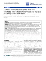
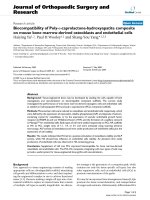
Figure 4-1 History of microfluidic device design.
(A) 3-channel microfluidic device, which is used to perform the pilot migration
study (B and C). The tissue spider device template and (D) The tissue 3-
channel device were designed for this study. (The later one was chosen and
produced for the rest of experiments).
!
87!
4.3.1 Design of microfluidic device
Auto-CAD (Autodesk, CA) was used to design the platform, including the
medium channels, tissue chambers, gel filling cages, and micro-pillar
dimensions (figure 4.2). The height of the channels is 250µm and other
dimensions are demonstrated in figure 4.2. In order to culture the tissue, the
device was created with one channel at the center for cells and two
semicircular channels at two sides delivering culture medium. The collagen
gel cages contain the tissue chambers. The tissue is embedded in the middle
of each gel cage. The side channels are used to deliver the nutrient to the
tissue. Triangular micro-pillar arrays help the housing of the scaffold in the gel
cage and preventing the gel overflow to the channels. The round micro-pillar
helps to secure the tissue at the same distance from the middle channel in
each side. By testing different gel concentration the gel cage filling was
optimized. The microfluidic channels, tissue chambers and gel cages were
cast in polydimethylsiloxane (PDMS), sterilized, and bonded to sterile glass
cover after placing the tissue in the device. To prevent the microbial
contamination the procedures were done in class II biosafety cabinet. The
channels were isolated from each other after placing the tissue in the gel
chamber and embedding it with the scaffold. Tissue can communicate with
middle channel through the gel by diffusion and concentration gradients of
secreted factors and it receives the nutrition through the lateral semicircular
channels. The arrangement allows concentration gradient of the chemotactic
factors secreted by the tissue toward the cell channel (middle channel). The
microfluidic device was designed to fit on the microscope stage for monitoring
88!
of tissue and cells interaction over time. Devices were put in 35mm diameter
dishes and incubated in 37°C humidified incubator with 5% CO
2
.
!
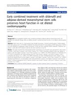
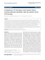
Figure 4-2 Schematic design and dimension of microfluidic device.
Upper panel shows a schematic image of the tissue microfluidic device. Blue
channels are the media channels, which are used for control and conditioned
media. Green channel is the MSCs culture channel. Pink channels are the
collagen filling area, and tissues will be embedded within the collagen scaffold
in these channels. Lower panel shows the Auto-CAD design of the
microfluidic platform; left image demonstrate the dimension of different parts
of the device and right image shows the arrangement of the devices in the
master wafer.
4.3.2 Computational modeling of concentration gradient
The computational modeling of the device was done with kind help of Dr. Kim
from BioSyM. Gradients of chemotactic factors within the collagen scaffold
were quantified by computational modeling using coupled transient
convection-diffusion and Brinkman equations, which were solved with a
commercial finite element solver in COMSOL (Burlington, MA) (230). In
89!
simulations, the diffusion constant of a 40 kDa (average size of factors) inert
molecule in the collagen matrix and the diffusion coefficients medium of 6 x 10
-11
m
2
/s were determined as previously described (230), the factor diffusion
coefficient in the scaffold was assumed to be 4.9 x 10
-11
m
2
/s, taken from the
reported values of Helm et al (231). A value of hydraulic permeability (K=10
-13
m
2
in the scaffold, where K is the hydraulic permeability of the collagen
matrix) was selected based on reports of Swartz et al. (232). Interstitial flow,
when applied, was created by imposing a pressure drop of 40 Pa between the
central channel and the gel region.
4.3.3 Fabrication of microfluidic device
A master silicon wafer was produced by photolithography (233) of the printed
Auto-CAD designed microfluidic device transparency mask on SU-8 mold.
Microfluidic devices were made by repeated molding of PDMS (Dow
Corning® Sylgard 184) on the silicon wafer, curing the polymer by cross-linker
at a ratio of 10:1 (according to the product protocol) and degassed the
elastomer and polymerizing it in 75°C oven for 2 hours. Polymerized PDMS
was detached from the wafers, each device punched out with a 35mm
diameter puncher, and the inlets were cut out by using 3mm (channel inlets)
and 1.2 mm (gel filling inlets). Prior to placing the tissue and bonding the glass
cover slips (#1.5 Cell Path, UK), PDMS and glass cover slips were cleaned
and autoclaved (20 min sterilization and 15 min dry). To facilitate the gel
filling, devices dried in the 75 °C oven overnight. The dried, sterile devices
were kept in sterile container and used within 2 days.
Pre-polymer solution of Collagen type I hydrogel (BD Biosciences Cat. No.
354236) was prepared in DMEM (Gibco BRL, Grand Island, NY, US),
90!
adjusted to pH 7.4 and kept on ice. The collagen type I hydrogel were injected
through the gel channels till fluid began to touch the triangular pillars. Next,
the devices were placed in the humidity chambers and incubated in the 37°C
humidified incubator for 30 min to polymerize the collagen gel. To stabilize the
collagen gel, complete culture media (DMEM supplemented with 10% FBS
(fetal bovine serum) (Gibco BRL, Grand Island, NY, US) and 1% antibiotics
(penicillin 100U/ml, streptomycin 0.1mg/ml) (Sigma, St Louis, Missouri, US))
was injected into all three media channels through the channel inlets and
incubated overnight. All the procedures were done in the class II biosafety
cabinet (BSC II) to prevent microbial contamination (contaminated devices
were discarded upon detection).
4.3.4 MSC characterization and culture in microfluidic devices
Ten milliliter bone marrow was aspirated from iliac crests of mature mini-pig
and cultured in the complete media (DMEM supplemented with 10% FBS
(fetal bovine serum) (Gibco BRL, Grand Island, NY, US) and 1% antibiotics
(penicillin 100U/ml, streptomycin 0.1mg/ml) (Sigma, St Louis, Missouri, US)
(each 10mL of bone marrow was cultured in one T-175 flasks) in a humidified
atmosphere of 5% CO2, at 37°C. After 4 days, non-adherent cells were
removed by washing (twice) with PBS and fresh medium was added. Cells
were cultured to reach 80-90 percent confluency (around 2x10
6
cells in a T175
culture flask), then, they detached by using TrypLE (Gibco BRL, Grand
Island, NY, US) and sub-cultured into two new flasks. Cells were expanded
and sub-cultured to get enough number of cells for the further experiments
(passage 4). The cells were detached and stained with the conjugated
antibodies against the hematopoietic, endothelial, and adhesion molecule
91!
markers (234)(adhesion molecules CD29, CD44, and CD90; hematopoietic
markers CD14, CD34, and CD45; and endothelial marker CD31). Stained
cells were characterized by flow cytometry and data acquired using
Dakocytomation system and analyzed by Summit SW version 4.3.02
(Beckman Coulter). The differentiation potential of the cells to adipocyte,
osteocyte and chondrocyte lineage was confirmed as well (see Chap 4). After
characterizing the cells at passage 3 (p3), cells were cultured in the
microfluidic devices in a concentration of 100,000 cells/channel to a final
confluency of 70-80%.
4.3.5 Microfluidic device migration validation
Migration were examined by culturing MSCs (passage 3) in complete media
and using the supplemented media with platelet derived growth factor
(PDGF), a known chemo-attractant for MSCs (235), in the conditioned
channel up to 5 days. This is used to confirm and validate the capability of our
designed microfluidic system to detect cell migration toward the gradient of
PDGF as a chemo-attractant factor.
4.3.6 Injured and uninjured sample preparation
An established ex vivo model was used to prepare the injured and uninjured
samples for further experiments (236). Three pairs of circular (6mm diameter)
pieces of cartilage tissues (6mm in diameter) were harvested from the female
mini-pigs by knee surgery.
One pair was used for preparation of the cartilage-conditioned media (injured
and uninjured). Explants were maintained in culture media for 6 days. Then,
the media of the samples were changed to fresh media; one piece kept
92!
uninjured in the media and the other explant was cut into pieces at 1mm
intervals and cultured in the media for 24 hours. Then, the media from both
explants used for the further experiments (figure 4.3).
The second pair was used for preparation of injured and uninjured tissues for
microfluidic experiments. The explants were cut to small pieces by using a
250µm diameter punch. After 6 days maintaining these tissues in media,
every two pieces were used in each microfluidic devices. One piece as
uninjured and the second piece cut into 4-5 smaller pieces as injured
samples.
The third pair of explants was used for the gene expression experiment; one
explant was immediately frozen in liquid nitrogen and used as uninjured
sample. The other one was cut at 1 mm intervals and cultured for 24 hours to
be used as injured sample.
4.3.7 MSCs migration toward injured cartilage conditioned media
Conditioned media were produced by culturing the cartilage tissues in the
complete media. As described before, two pieces of cartilage from the same
porcine knee femoral condyle with the same size (6 mm in diameter) and
weight were excised and cultured for 6 days to wash out endogenous chemo-
attractants (236). After these 6 days, the media of samples exchanged with
fresh media and one of these samples was cut to 1x1mm pieces as shown in
figure 4.3 and the other sample kept as uninjured sample for further
experiments. After one day these conditioned media from the both samples
were used in six channels (three uninjured conditioned media and three
injured conditioned media) to determine the effect of the acute cartilage
injuries on the migration of the MSCs (236). The media in the microfluidic
93!
devices were replaced daily with conditioned media for 5 days. To prevent the
tissue dryness, the same amount of the complete media, which used for
migration assay were added to the tissues daily.
!
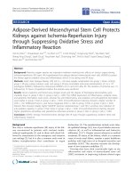
Figure 4-3 Cartilage tissue conditioned media preparation.
Uninjured (left) and injured (right) cartilage tissue conditioned media
preparation.
4.3.8 Tissue placement and device assembly
As mentioned before pre-polymer solution of Collagen type I hydrogel (BD
Biosciences Cat. No. 354236) was prepared in DMEM (Gibco BRL, Grand
Island, NY, US), adjusted to pH 7.4 and kept on ice. Pieces of porcine
articular cartilage tissues (250 µm thickness) were cut and placed in the tissue
chamber and channels were sealed by a sterile cover glass. The collagen
type I hydrogel were injected through the gel channels till fluid began to touch
the triangular pillars. To prevent air-bubble and incomplete filling of the cages,
two gel filling channels are designed into the device. Next, the devices were
placed in the humidity chambers and incubated in the 37°C humidified
incubator for 30 min to polymerize the collagen gel. To stabilize the tissue,
complete culture media (DMEM supplemented with 10% FBS (fetal bovine
serum) (Gibco BRL, Grand Island, NY, US) and 1% antibiotics (penicillin
94!
100U/ml, streptomycin 0.1mg/ml) (Sigma, St Louis, Missouri, US)) was
injected into all three media channels through the channel inlets and
incubated overnight. All the procedures were done in the class II biosafety
cabinet (BSC II) to prevent microbial contamination (contaminated devices
were discarded upon detection).
4.3.9 MSCs migration toward injured tissue
Injured cartilage was embedded in the tissue chamber of the microfluidic
devices to determine the effect of the tissue on the migration of the MSCs. A
piece of 1.5 mm in length and 200 µm diameter core of the articular cartilage
was placed in one of the tissue chambers of the device and the same size of
the cartilage tissue core was cut to 4-5 pieces and placed in the other tissue
chamber as the injured tissue and both embedded by the collagen type I
scaffold. The MSCs were cultured in the middle channel and complete media
were added to all channels. The migration of the MSCs toward the gradient of
chemo-attractants secreted by tissues was evaluated in six devices (six
uninjured tissue embedded channels and six injured tissue embedded
channels) daily by light microscopy. As the migration of the cells toward the
tissues was faster than using the conditioned medias, I evaluated the
migration till the time that cells reach the tissues, up to 3 days, to exclude the
effect of the blockage of the migration by the tissues, as a confounding factor.
4.3.10 Quantification of the MSCs migration
The average migration distance of MSCs was quantified by measuring the
area occupied by MSCs in collagen channel (manually drawn region of
interests (ROI)) and dividing the occupied area by the width of collagen
95!
channel using ImageJ software version 1.45s, developed by National
Institutes of Health (it is showed as “A” in figure 4-7 and 4-9). Each area (A)
was calculated for each channel separately (e.g. “A
Uninjured media
“, ”A
Injured
media
“, “A
Uninjured tissue
“, and “A
Injured tissue
”). Then, to calculate the average
migration distance of the cells in each channel, the calculated areas were
divided by length of the base of collagen channel (it is showed as “L” in figure
4-7 and 4-9).
Average migration distance =
A (Migration area in collagen channel)
L (Length of collagen channel base)
The calculated distances of MSCs migration against uninjured and injured
cartilage tissues were compared and also calculated distances of MSCs
migration against uninjured and injured conditioned media were compared.
For a better visualization of the cells in the collagen channel, the cells
migration ROIs were determined by ImageJ software, and an intensity
threshold level was established for discrimination between migrated cells and
the background. The masks of the outlined cells (cells’ masks) were plotted
and displayed in the middle panel of figures 4-6, 4-7, and 4-9.
4.3.11 Quantitative real-time reverse transcriptase-polymerase chain
reaction (RT-PCR)
Each frozen sample was crushed in the liquid nitrogen using chilled mortar
and pestle and suspended in TRIzol reagent (Invitrogen, CA, USA) (236).
Crush samples were incubated on ice for 10 minutes with vortex mixing every
2 minutes. Chloroform (Invitrogen, Carlsbad, CA, USA) was added to each
samples and vortex mixed for 2 minutes. The sample is centrifuged at 4
o
C for
10 minutes at 10,000 rpm. The aqueous phase collected and the total RNAs
96!
were extracted by using QIAGEN® RNeasy kit. The DNase (QIAGEN®, USA)
was used to eliminate the possible contamination of DNA. The extracted RNA
quantity and quality was assessed using NanoDrop spectrophotometer.
The same amounts of the extracted total RNA of the uninjured and injured
articular cartilage samples were used to prepare the complementary DNA
(cDNA) with the iScript™ cDNA Synthesis Kit (Biorad, USA). RT-PCR was
performed against different chemokines, cytokines, ligands, and growth
factors, which could be involved in the MSC migration stimulation according to
published literature (Table 3.1) (52, 146, 148-150, 152-154, 157-161, 163,
165, 237-246). Custom-made RT-PCR plate (Applied Biosystems, USA)
against the porcine factors was used to compare uninjured and injured
samples. Glyceraldehyde 3-phosphate dehydrogenase (GAPDH) was used as
a housekeeping control gene to normalize the results. The results were
analyzed by 7500 System SDS V1.4.0 software (Applied Biosystems, CA,
USA).
!
97!
Table 4-1. List of candidate ligands used for RT-PCR analysis.
These factors were chosen according to published literatures (52, 146, 148-
150, 152-154, 157-161, 163, 165, 237-246), which demonstrated their
involvement in the MSC migration.
!
!
Symbol
Description
Cxcl 12
Chemokine (C-X-C motif) ligand 12
Il 1a
Interleukin 1alpha
Il 1b
Interleukin 1beta
Il 6
Interleukin 6
Tnf
Tumor necrosis factor
Tgfb1
Transforming growth factor beta 1
Tgfb2
Transforming growth factor beta 2
Tgfb 3
Transforming growth factor beta 3
Bmp2
Bone morphogenetic protein 2
Bmp4
Bone morphogenetic protein 4
Bmp7
Bone morphogenetic protein 7
Fn 1
Fibronectin 1
Vtn
Vitronectin
Col 1a1
Procollagen, type 1, alpha 1
Angpt 1
Angiopoietin 1
Angpt2
Angiopoietin 2
Vegf a
Vascular endothelial growth factor A
Igf 1
Insulin-like growth factor 1
Ihh
Indian hedgehog homolog, (Drosophila)
Igf 2
Insulin-like growth factor 2
Fgf 2
Fibroblast growth factor 2
Mmp 7
Matrix metallopeptidase 7
Cx3cl 1
Chemokine (C-X3-C motif) ligand 1
Egf
Epidermal growth factor
Hbegf
Heparin-binding EGF-like growth factor
Tgf a
Transforming growth factor alpha
F2
Coagulation factor II
Ccl 2
Chemokine (C-C motif) ligand 2
Ccl 5
Chemokine (C-C motif) ligand 5
Lif
Leukemia inhibitory factor
Ntf3
Neurotrophin 3
Cxcl 10
Chemokine (C-X-C motif) ligand 10
Csf 2
Colony stimulating factor 2 (gran-macrophage)
Csf 3
Colony stimulating factor 3 (granulocyte)
Ibsp
Integrin binding bone sialoprotein
98!
4.3.11 Statistical analysis
Two-way ANOVA with Bonferroni’s multiple comparison adjustment was used
to evaluate the statistical differences between the migration distances of the
MSCs between groups (e.g., complete media, uninjured and injured cartilage
tissue, and respective conditioned medias). A p value of less than 0.05 was
considered as significant differences.
99!
4.4 Results
4.4.1 Computational modeling of concentration gradient
Chemo-attractive factors can diffuse into the hydrogel scaffold, mimicking the
incorporation of cytokines into the native extracellular matrix (ECM) in the in
vivo paradigm. Numerical simulations based on a transient solution of the
Brinkman equation for porous medium flow and the convection-diffusion
equation for factor concentrations demonstrated the development of a nearly
linear concentration gradient of growth factors in tissue microfluidic device
(Figure 4.4).
!
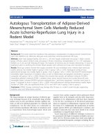
Figure 4-4. The growth factors diffusion simulation in 3D scaffold.
The diffusion simulation toward the 3D scaffold region confirmed the
generation of concentration gradient across the collagen matrix, which was
nearly linear (C=0 considered as control solution and C=1 as experimental
solution which contains growth factor).
!
100!
4.4.2 MSC characterization
MSCs were trypsinized from the flasks, stained and analyzed by flow
cytometry. The cells were positive for adhesion molecules CD29, CD44 and
CD90 and negative for hematopoietic markers CD14, CD34 and CD45, and
endothelial marker CD31 (Figure 4.5). In addition cells could differentiate to all
three adipogenic, osteogenic, and chondrogenic lineage (data showed in
chapter 3).
!
Figure 4-5. Flow cytometry analysis of the stem cells surface markers.
Harvested cells were positive for CD29, CD44, and CD90, and negative for
CD14, CD31, CD45, and CD34.
!
101!
4.4.3 Microfluidic device migration validation
The devices contained complete media in both channels showed the same
migration distance of the MSCs (Figure 4.6A). Longer distances of migration
by MSCs were observed in the PDGF conditioned media comparing to control
(figure 4.6B). The result confirmed that (a) chemotactic factors can diffuse into
the 3D hydrogel scaffold and (b) MSCs will migrate in response to the
gradient within the device.