Performance evaluation of personalized ventilation personalized exhaust (PV PE) system in air conditioned healthcare settings 7
Bạn đang xem bản rút gọn của tài liệu. Xem và tải ngay bản đầy đủ của tài liệu tại đây (793.58 KB, 17 trang )
Chapter 7: Performance evaluation of PE system alone in
conjunction with background MV and DV systems —
airborne infection control
!
7.1 Introduction and Objective
In Chapter 6, the combined PV-PE system was studied under both MV and DV in the
context of airborne infection control. One PE was applied for Infected Person while
the other PE was combined with PV system for the HP. The observations of combined
PV-PE system indicated that using a PE for IP is much more efficient than using PV
or combined PV-PE for HP in terms of reducing the exposure to cross-contaminated
air. Furthermore, after activating the PE for IP, the use of PV or combined PV-PE for
HP may bring more contaminated air to the breathing zone of HP in some
configurations.
In addition, while Chapter 6 focuses on a normal consultation procedure in healthcare
settings with one IP sitting facing the HP, the distance between the HP and the IP is
enough for the PV ATD. However, in real situations, Healthy Person (doctor, nurse,
etc.) does not always face the Infected Person as a typical position arrangement.
More position arrangements with closer distance between the HP and the IP need to
be considered. During simple sampling or medical check-ups, the doctor may shift
his/her position where the HP no longer faces the IP with a closer distance, or the HP
may stand up and come in close proximity to the IP. In these circumstances, HP may
move away from his/her consultation desk and there is no space for PV ATD.
It is subsequently interesting to know how the PE alone for IP performs when the
Healthy Person is exposed to the exhaled contaminated air from IP. It is also
important to observe where the protection is strong enough with closer distance, or
which configuration would result in higher exposure.
In view of these situations, the objective of this chapter explores performance of PE
system alone in conjunction with background MV and DV in terms of airborne
infection control while Infected Person seated under two different configurations by
the side of the seated Healthy Person, as well as when the Healthy Person is standing
facing the seated Infected Person.
The experimental design and evaluation index are described in Chapter 3 (Section
3.5.4). Experimental chamber is described in Section 3.4.1.1.
7.2 Performance of the PE alone for preventing transmission of exhaled
contaminated air in three different positions between IP and HP
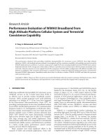
PE is introduced as a different arrangement in Cases B, C, and D (Figure 7.1). Case B
is the shifting of HP to 45 degree to the IP, which can happen during both
consultation process and simple medical check-up procedure. Case C is thought to be
an example of some careful examination pattern, with both the HP and IP seated. And
case D represents the Healthy Person standing close to a seated Infected Person. It is
a situation in which the HP has stood up and walked towards the IP to take simple
medical test or conduct some simple treatment. In these three cases, the distance
between the two manikins is 0.45 m.
Figure 7.1 Different arrangements between HP and IP (left: case B, middle:
case C, right: case D)
7.2.1 Comparison of iF between the three cases.
With a sense of the impact of the background ventilation system on the flow pattern
of the indoor air, thus influencing the concentration of exhaled contaminated air at the
breathing zone of HP; it is useful to compare the iF of the three cases to determine the
effect of background ventilation system and the PE combined background ventilation
on HP exposure. Figure 7.2 through Figure 7.5 compare the iF with and without two
types of PE with MV and DV. Generally, in all the four Figures, after activating the
PE (either top-PE or shoulder-PE) at 10 l/s, iF drops sharply. And the iF is further
reduced as the PE flow rate increases from 10 l/s to 20 l/s.
Figure 7.2 Comparison of iF when using top-PE with MV
Figure 7.3 Comparison of iF when using shoulder-PE with MV
0.00E+00!
2.00E'03!
4.00E'03!
6.00E'03!
8.00E'03!
1.00E'02!
1.20E'02!
1.40E'02!
1.60E'02!
1.80E'02!
no!PE! top'PE!10l/s! top'PE!20l/s!
!"#
$%#
Case!B!
Case!C!
Case!D!
0.00E+00!
2.00E'03!
4.00E'03!
6.00E'03!
8.00E'03!
1.00E'02!
1.20E'02!
1.40E'02!
1.60E'02!
1.80E'02!
no!PE! shoulder'PE!
10l/s!
shoulder'PE!
20l/s!
!"#
$%#
Case!B!
Case!C!
Case!D!
Figure 7.4 Comparison of iF when using top-PE with DV
Figure 7.5 Comparison of iF when using shoulder-PE with DV
In the baseline cases without any PE switched on with MV; consider the iF of Figure
7.2 and Figure 7.3. It is observed that the iF of case B is the highest, followed by case
D, and lastly the case C. This is because with mixing ventilation alone, the airflow
with high velocity supplied from the four-way ceiling diffuser generated relatively
high turbulence in the occupied zone, thus promoting intensive mixing and spread of
exhaled air form IP to the surroundings. Therefore, in case B, the 45 degree between
the HP and IP with a short distance of only 0.45 m enables the exhaled air to reach the
HP in a higher amount. In Case C, although the IP is exhaling directly towards the HP,
0.00E+00!
2.00E'03!
4.00E'03!
6.00E'03!
8.00E'03!
1.00E'02!
1.20E'02!
1.40E'02!
no!PE! top'PE!10l/s! top'PE!20l/s!
!"#
&%#
Case!B!
Case!C!
Case!D!
0.00E+00!
2.00E'03!
4.00E'03!
6.00E'03!
8.00E'03!
1.00E'02!
1.20E'02!
1.40E'02!
no!PE! shoulder'PE!
10l/s!
shoulder'PE!
20l/s!
!"#
&%#
Case!B!
Case!C!
Case!D!
the exhaled air does not travel straight to the HP due to the well-mixing effect, thus
resulting in the lowest iF.
With Displacement Ventilation alone in Figure 7.4 and Figure 7.5, the flow in contact
with the Infected Person assisted the free convection flow around the Healthy Person
to transport the exhaled contaminated air upward to the breathing zone of HP.
Therefore, highest iF is found in case D. In Case C, it could be envisaged that weak
mixing and strong stratification in the room is able to promote the lateral dispersion of
exhaled air and therefore the exhaled air can travel longer distance to the HP
breathing zone. In this case, the IP is also higher compared with case B, in which the
IP is exhaling not directly towards the HP.
In Figure 7.6, iF is displayed in five groups to compare the values between without
PE and with different types of PE. In each of these groups, there are two clusters, each
representing the values with MV and DV.
Figure 7.6 Comparison of iF when using different PE configurations
The PE combined with total volume ventilation (either MV or DV) always reduces
the Intake Fraction in regard to the exhaled air from IP. It is interesting to note that the
type of background ventilation system has a substantial impact on the travel of
exhaled air. In case B, the MV always leads to a higher iF than DV with or without
0.00E+00!
2.00E'03!
4.00E'03!
6.00E'03!
8.00E'03!
1.00E'02!
1.20E'02!
1.40E'02!
1.60E'02!
1.80E'02!
DV! MV! DV! MV! DV! MV! DV! MV! DV! MV!
No!PE! shoulder'
PE!10l/s!
top'PE!10l/
s!
shoulder'
PE!20l/s!
top'PE!20l/
s!
!"#
Case!B!
Case!C!
Case!D!
PE. The infected air is transported to the breathing zone of the HP by the mixing
effect around the two persons. The high velocity and turbulence intensity with MV
promotes the exhaled air to travel towards the 45 degree direction. Different patterns
are observed in case C and case D, where DV results in higher exposure than MV,
especially when PE is not used or at a low flow rate of 10 l/s. This is because the DV
enhances the forward and upward movement of the exhaled air.
By comparing group 2 and group 3, as well as group 4 and group 5, it is seen that for
most of the cases, top-PE can lead to a lower iF than shoulder-PE at the same flow
rate. This agrees with the observation in Chapter 6 that top-PE has a better
performance.
7.2.2 Comparison of Exposure Reduction after using PE
The evaluation index Exposure Reduction was described in section 3.5.3. A direct
comparison of the PE performance will be made by comparing the exposure reduction
for each base case.
Figure 7.7 through Figure 7.9 display the Exposure Reduction when applying
different PE strategies. The base case using the same flow rate with the same type of
PE with MV and DV are not comparable.
The top-PE, having a circular cross-section outlet above the head of IP, generated
better exposure reduction for most cases. The largest difference is around 40% when
the flow rate is 10 l/s with DV in case D. This is because the suction flow together
with the upward thermal plume brings more exhaled air to the opening. One
exceptional case is when PE is set at 20 l/s with DV in case D, where the exposure
reduction while utilizing top-PE is almost the same as using shoulder-PE. With DV in
case B, the exposure reduction when using top-PE at 10 l/s is 18% higher than when
shoulder-PE is set at 20 l/s; while with MV in case B, the exposure reduction after
setting 10 l/s for top-PE is 3% higher than that using 20 l/s of shoulder-PE. Similar to
the findings in case B, the results in Figure 7.8 show that a rather lower flow rate of
top-PE (10 l/s) reduce more exposure with a higher flow rate of shoulder-PE (20 l/s).
The difference is 12% with MV and 10% with DV. The results of this investigation in
case D show that the increase of flow rate has a larger impact on the exposure
reduction than case B and C.
Figure 7.7 Comparison of Exposure Reduction in case B
Figure 7.8 Comparison of Exposure Reduction in case C
0.00%!
10.00%!
20.00%!
30.00%!
40.00%!
50.00%!
60.00%!
70.00%!
80.00%!
90.00%!
100.00%!
MV! DV! MV! DV!
PE!10l/s! PE!20l/s!
'()*+, #/.0,12*3#
45+.#6#
Top'PE!
Shoulder'PE!
0.00%!
10.00%!
20.00%!
30.00%!
40.00%!
50.00%!
60.00%!
70.00%!
80.00%!
90.00%!
MV! DV! MV! DV!
PE!10l/s! PE!20l/s!
'()*+, #/.0,12*3#
45+.#4#
Top'PE!
Shoulder'PE!
Figure 7.9 Comparison of Exposure Reduction in case D
7.2.3 Change of Intake Fraction with time
For infectious transmission control concerns, both the exposure duration and the
concentration of the infection are critical factors. For the three cases with closer
distances, higher concentration of exhaled air is measured at the breathing zone of HP,
thus the change of iF over the half hour of the three cases when no PE is used is
shown in Figure 7.10. In general, the iFs in the three cases increase with time,
especially for the first 10 minutes. Consequently, it is supposed to be important to
exhaust the exhaled air as early as possible after the IP enters the room. However, in
real situation, a Healthy Person would not know if patients are infected or not before
the Infected Person is diagnosed and is moved to an isolation room, so the
effectiveness of ventilation system in removing the exhaled infectious air in the
consulting room becomes important.
0.00%!
10.00%!
20.00%!
30.00%!
40.00%!
50.00%!
60.00%!
70.00%!
80.00%!
90.00%!
100.00%!
MV! DV! MV! DV!
PE!10l/s! PE!20l/s!
'()*+, #/.0,12*3#
45+.#&#
Top'PE!
Shoulder'PE!
Figure 7.10 Changes of iF over time when no PE is used
Figure 7.11 through Figure 7.16 compare the iF with and without PE over time. It is
observed that for all cases, after applying either top-PE or shoulder-PE, the Inhaled
Fraction is significantly decreased. With the higher flow rate of 20 l/s of PE, the iFs at
30 minutes are even lower than the ifs at 10 minutes without PE. For example, in Case
C with DV, the iF at 10 minutes without PE is as high as 4.85e-3; after the top-PE
operates at 20 l/s, the iF is measured at 1.21e-3 at 30 minutes while 2.12e-3 if
recorded with the use of shoulder-PE at 30 minutes. This implies that the infection
risk is reduced by reducing the exposure amount for longer exposure time. In addition,
the iF after activating top-PE is always lower than that when using shoulder-PE at the
same flow rate at any time interval. This agrees with the conclusion in Chapter 6 that
top-PE performs better than shoulder-PE in terms exhausting the exhaled air.
0!
0.002!
0.004!
0.006!
0.008!
0.01!
0.012!
0.014!
0.016!
0.018!
0! 10! 20! 30!
!"#
7!8.#98!3+:#
;*#<'#
Case!B!+MV!
Case!C!+MV!
Case!D!+MV!
Case!B!+DV!
Case!C!+DV!
Case!D!+DV!
Figure 7.11 Changes of iF over time in Case B with MV
Figure 7.12 Changes of iF over time in Case B with DV
0.00E+00!
2.00E'03!
4.00E'03!
6.00E'03!
8.00E'03!
1.00E'02!
1.20E'02!
1.40E'02!
1.60E'02!
1.80E'02!
!"#
45+.#6#=!>?#$%#
10mins!
20mins!
30mins!
0.00E+00!
5.00E'04!
1.00E'03!
1.50E'03!
2.00E'03!
2.50E'03!
3.00E'03!
3.50E'03!
4.00E'03!
4.50E'03!
!"#
45+.#6#=!>?#&%#
10mins!
20mins!
30mins!
Figure 7.13 Changes of iF over time in Case C with MV
Figure 7.14 Changes of iF over time in Case C with DV
0.00E+00!
1.00E'03!
2.00E'03!
3.00E'03!
4.00E'03!
5.00E'03!
6.00E'03!
7.00E'03!
8.00E'03!
!"#
45+.#4#=!>?#$%#
10mins!
20mins!
30mins!
0.00E+00!
1.00E'03!
2.00E'03!
3.00E'03!
4.00E'03!
5.00E'03!
6.00E'03!
7.00E'03!
8.00E'03!
9.00E'03!
!"#
45+.#4#=!>?#&%#
10mins!
20mins!
30mins!
Figure 7.15 Changes of iF over time in Case D with MV
Figure 7.16 Changes of iF over time in Case D with DV
7.3 Air temperature and velocity
The room air temperature and mean velocity are recorded at heights of 0.1 m, 0.3 m,
0.7 m, 1.3 m, 1.65 m and 1.95 m using the DANTEC instrument. The vertical room
air temperature distribution is presented in Figure 7.17.
0.00E+00!
2.00E'03!
4.00E'03!
6.00E'03!
8.00E'03!
1.00E'02!
1.20E'02!
1.40E'02!
!"#
45+.#&#=!>?#$%#
10mins!
20mins!
30mins!
0.00E+00!
1.00E'03!
2.00E'03!
3.00E'03!
4.00E'03!
5.00E'03!
6.00E'03!
7.00E'03!
8.00E'03!
9.00E'03!
!"#
45+.#&#=!>?#&%#
10mins!
20mins!
30mins!
Figure 7.17 Room air temperature with MV and DV
The data collected by DANTEC instrument shows the room air temperature at various
heights Vertical temperature gradient is observed along the heights of the room with
DV, while the temperature profile with MV shows a well-mixed condition. From 0.3
m to 1.3 m, the vertical temperature gradient profiles with DV became steeper, which
is the influence of the two seated thermal manikins.
The room air mean velocity with MV and DV is presented in Figure 7.18. The higher
air movement is observed with MV than DV. The reported velocities were the average
values taken at the four locations at each height.
Figure 7.18 Room air velocity with MV and DV
21.8!
22!
22.2!
22.4!
22.6!
22.8!
23!
23.2!
0.1m! 0.3m! 0.7m! 1.3m! 1.65m! 1.95m!
7.8) 5>, #
@.!A?>#5B*C.#D**-#
MV!
DV!
0!
0.05!
0.1!
0.15!
0.2!
0.25!
0.1m! 0.3m! 0.7m! 1.3m! 1.65m! 1.95m!
%.E*1!>F#
@.!A?>#5B*C.#D**-#
MV!
DV!
The results in Figures 7.19 and Figure 7.20 show that the mean air velocity is higher
at a height of from 0.3 m to 1.3 m with both MV and DV where the PE was mounted
than without PE. This is because the use of the PE enhanced the convection airflow
around the thermal manikin, hence increased the air velocities at the locations
measured not far from the manikins. It can also be seen that higher the PE flow rate is,
higher is the air velocity measured with DV. However, with MV, there is not much
difference between PE at 10 l/s and 20 l/s.
Figure 7.19 Room air velocity with and without PE with DV
Figure 7.20 Room air velocity with and without PE with MV
The results in Figures 7.21 and 7.22 show that the Infected Manikin was prone to
higher air velocities at neck/ear region where the PE were switched on than without
0!
0.02!
0.04!
0.06!
0.08!
0.1!
0.12!
0.1m! 0.3m! 0.7m! 1.3m! 1.65m! 1.95m!
%.E*1!>F#
@.!A?>#5B*C.#D**-#
No!PE!
PE!10l/s!
PE!20l/s!
0!
0.05!
0.1!
0.15!
0.2!
0.25!
0.1m! 0.3m! 0.7m! 1.3m! 1.65m! 1.95m!
%.E*1!>F#
@.!A?>#5B*C.#D**-#
$%#
No!PE!
PE!10l/s!
PE!20l/s!
PE. The velocity increases as the PE flow rate increases. When the results obtained
with shoulder-PE are compared with the results obtained with the top-PE, it is
observed that shoulder-PE generated higher velocity at neck/ear region of the Infected
Manikin, especially with DV. This implies that the shoulder-PE which is located near
to the neck/ear region may lead to higher air movement around the head.
Figure 7.21 Local air velocity at neck/ear region with MV
Figure 7.22 Local air velocity at neck/ear region with DV
Figure 7.23 and Figure 7.24 show the Draft Rating (DR) in the space close to the
manikin’s neck/ear region (1.2 m). Higher draft rating is recorded after switching on
the PE. Since the draft is an unwanted local cooling of the body caused by air
movement, the increase of draft rating is not preferred. The figures show that the
No!PE! PE!10l/s! PE!20l/s!
shoulder'PE!
0.17!
0.235!
0.28!
top'PE!
0.17!
0.23!
0.25!
0!
0.05!
0.1!
0.15!
0.2!
0.25!
0.3!
G!-#%.E*1!>F#
$%#
No!PE! PE!10l/s! PE!20l/s!
shoulder'PE!
0.11!
0.25!
0.29!
top'PE!
0.11!
0.15!
0.18!
0!
0.05!
0.1!
0.15!
0.2!
0.25!
0.3!
0.35!
G!-#C.E*1!>F#
&%#
increase of PE flow rate also brings an increase of DR at the neck/ear. With the higher
flow rate of PE (20 l/s), the DR increases to more than 15%, and a value of around 15%
is observed with the lower flow rate of 10 l/s. This means that further consideration is
needed when using PE regarding the draft risk.
Figure 7.23 Draft rating at neck/ear region of IP with MV
Figure 7.24 Draft rating at neck/ear region of IP with DV
7.4 Key Findings
The major findings from this particular study on the influence of different
arrangement between HP and IP, PE types and PE flow rate, and back ground
ventilation type to the airborne transmission contaminated air exhaled by an IP are as
follows:
0.00%!
5.00%!
10.00%!
15.00%!
20.00%!
25.00%!
No!PE! PE!10l/s! PE!20l/s!
&-5H#/523A#
$%#
shoulder'PE!
top'PE!
0.00%!
2.00%!
4.00%!
6.00%!
8.00%!
10.00%!
12.00%!
14.00%!
16.00%!
18.00%!
No!PE! PE!10l/s! PE!20l/s!
&-5H#/523A#
&%#
shoulder'PE!
top'PE!
The type of background air distribution system has an impact on the flow pattern of
exhaled air. With MV, when PE is not used, the highest exposure possibility is when
the HP and IP are 45 degrees to each other (case B). Case C (HP and IP are 90 degree
to each other) will lead to the lowest exposure of exhaled contaminated air. With DV,
case D (HP standing facing the seated IP) will result in highest exposure of the HP
while case B can achieve the best protection for the HP among the three cases when
PE is not switched on.
After using either shoulder-PE or top-PE, the transmission of exhaled air to the HP’s
breathing zone is largely reduced. The performance of top-PE is better than that of the
shoulder-PE since it achieves better protection with lower flow rate, thus saving
energy and reducing the noise level.
For infectious transmission control concerns, both the exposure duration and the
concentration of the infection are critical factors. The longer the IP stays in the
consulting room, the higher the exposure and risk for the HP. By using PE for the IP,
the exposure at 30 minutes after entering the consultation room of the IP is lower than
the exposure at 10 minutes without PE.
However, there is a draft risk (Draft Rating is more than 15%) potential after using the
PE. Further investigation on the subjective acceptability of PE may be needed.
!