Theoretical and experimental studies on the promoting effect of boron on cobalt catalyst used for fischer tropsch synthesis
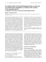
Bạn đang xem bản rút gọn của tài liệu. Xem và tải ngay bản đầy đủ của tài liệu tại đây (4.48 MB, 183 trang )
THEORETICAL AND EXPERIMENTAL STUDIES ON
THE PROMOTING EFFECT OF BORON ON COBALT
CATALYST USED FOR FISCHER-TROPSCH SYNTHESIS
(FTS)
TAN KONG FEI
NATIONAL UNIVERSITY OF SINGAPORE
2012
THEORETICAL AND EXPERIMENTAL STUDIES ON THE
PROMOTING EFFECT OF BORON ON COBALT CATALYST
USED FOR FISCHER-TROPSCH SYNTHESIS (FTS)
TAN KONG FEI
(B. Eng. & M. Phil., University of Malaya, Malaysia
M.Sc., Singapore MIT Alliance, Singapore)
A THESIS SUBMITTED
FOR THE DEGREE OF DOCTOR OF PHILOSOPHY
DEPARTMENT OF CHEMICAL & BIOMOLECULAR ENGINEERING
NATIONAL UNIVERSITY OF SINGAPORE
2012
I
ACKNOWLEDGEMENTS
I would like to take this opportunity to extend my gratitude and appreciation to my main
supervisor, Dr. Mark Saeys from NUS. Through him, I learnt invaluable lessons in my
research. He was pivotal in guiding me throughout my PhD research.
I am also indebted to my co-supervisor, Dr. Armando Borgna from ICES for his
supervision throughout my experimental studies in ICES. Without his supervision and
help, I would not be able to complete my studies. There are others in ICES which I am
equally indebted to, for without their help and support, I would not be able to
successfully wrap up my experiments. Therefore, my sincere appreciation to Dr. Chang
Jie, Dr. Chen Luwei, Dr. James Highfield, Dr. Ang Thiam Peng, Mr. Lee Koon Yong
and Ms. Wang Zhan.
To my senior, Dr. Xu Jing who mentored me in the usage of VASP and provided me
with all the technical guidance, I thank you. To Sun Wenjie, Gavin Chua Yong Ping,
Fan Xuexiang, Zhuo Mingkun, Su Mingjuan, Ravi Kumar Tiwari and Trinh Quang
Thang who are my colleagues/lab mates, I thank you for your help, support,
camaraderie and encouragement throughout my research work.
Finally, special thanks to my dear wife Loo Yen Hoong, for being there to support me as
I pursue my doctorate degree. I am extremely grateful for her love, patience and
especially her understanding, which have enabled my doctorate journey to be
meaningful and successful. To my personal savior, Lord Jesus Christ, to whom all glory
resides, thank you for the grace and sustenance to complete this journey.
II
TABLE OF CONTENTS
Acknowledgements ············································································································ I
Table of contents ···············································································································II
Summary·························································································································· VI
Symbols and abbreviations································································································X
List of tables ··················································································································XIII
List of figures ·················································································································XV
Publications ····················································································································XX
Chapter 1 Introduction······································································································· 1
1.1
References·············································································································· 4
Chapter 2 Literature Review on the Reaction Chemistry and the Deactivation of Cobalt
Catalysts in FTS ················································································································ 6
2.1
Introduction············································································································ 6
2.2 Fischer-Tropsch Mechanism·················································································· 9
2.2.1 Carbide Mechanism ······················································································· 9
2.2.2 Formation of Methylene (CH
2
) species························································ 10
2.2.3 The Alkyl Mechanism·················································································· 11
2.2.4 The β-hydride Elimination Mechanism ······················································· 13
2.2.5 Formation of Linear Alkanes ······································································· 13
2.2.6 CO Insertion and Hydrogen Assisted CO Activation Mechanism ·············· 14
2.2.7 The Alkenyl Mechanism·············································································· 16
2.3 Catalyst Deactivation··························································································· 19
2.3.1 Introduction·································································································· 19
2.3.2 Catalyst Re-oxidation ·················································································· 21
III
2.3.3 Formation of Cobalt Aluminate Species······················································ 23
2.3.4 Formation of Carbonaceous Deposits ·························································· 24
2.3.5 Formation of Bulk Carbide ·········································································· 25
2.3.6 Formation of Subsurface Carbon ································································· 26
2.3.7 Formation of Carbon Oligomers as Precursors to Polymeric Carbon·········· 26
2.3.8 Carbon Induced Surface Reconstruction······················································ 28
2.3.9 Effects of Sintering ······················································································ 31
2.3.10 Sulphur and Nitrogen Poisoning································································ 35
2.4 Enhancing the Stability of FTS Cobalt Catalyst ·················································· 36
2.4.1 Boron Promotion···························································································· 36
2.4.2 Noble Metal Promotion·················································································· 37
2.4.3 Alkali Metal Promotion ················································································· 38
2.4.4 Carbon suppression with Supercritical Fluid ················································· 38
2.5 Regenerating Spent FTS Cobalt Catalyst····························································· 40
2.6 Summary ············································································································· 44
2.7 References ··········································································································· 45
Chapter 3 Computational and Experimental Methods ··················································· 52
3.1 Computational Theory························································································· 52
3.1.1 What is Density Functional Theory (DFT)? ················································ 52
3.1.2 The Vienna Ab Initio Simulation Package (VASP) ···································· 52
3.2 Computational Methodology ·············································································· 53
3.3 Experimental Methodology················································································· 62
3.3.1 Catalyst Synthesis ·························································································· 62
3.3.2 Temperature Programmed Reduction (TPR) and H
2
Chemisorption ············ 63
3.3.3 Brunauer-Emmett-Teller (BET) Measurements ············································ 65
3.3.4 X-Ray Diffraction (XRD)·············································································· 66
IV
3.3.5 Diffuse Reflectance Infrared Fourier Transform Spectroscopy (DRIFTS) ··· 67
3.3.6 X-Ray Photoelectron Spectroscopy (XPS) ···················································· 68
3.3.7 Temperature Programmed Hydrogenation (TPH) and Thermal Gravimetric
Analysis (TGA) ····························································································· 71
3.3.8 High Resolution Transmission Electron Microscopy (HRTEM) ·················· 72
3.3.9 Fischer-Tropsch Synthesis (FTS) ·································································· 73
3.4
References··········································································································· 80
Chapter 4 Carbon Deposition on Cobalt Catalysts during Fischer-Tropsch Synthesis: A
Computational and Experimental Study ························································ 84
4.1 Results and Discussion························································································ 84
4.1.1 Reduction Profile for Supported Cobalt Catalysts········································· 84
4.1.2 Deactivation Behavior of Supported Cobalt Catalyst during Fischer-
Tropsch Synthesis ·························································································· 87
4.1.3 Characterization of Supported Cobalt Catalyst after Fischer-Tropsch
Synthesis ········································································································ 90
4.1.4 Computational Evaluation of the Relative Stability of Various Forms of
Deposited Carbon··························································································· 98
4.2 Conclusions ······································································································· 108
4.3 References ········································································································· 109
Chapter 5 Effect of Boron Promotion on the Stability of Cobalt Fischer-Tropsch
Catalyst ········································································································ 114
5.1 Results and Discussion······················································································· 114
5.1.1 Computational Study of the Stability of Boron on a Cobalt Surface ········· 114
5.1.2 Catalyst Characterization············································································ 125
5.1.3 Effect of Boron Promotion on the Catalyst Activity, Selectivity
and Stability································································································ 132
5.2 Conclusions ······································································································· 142
V
5.3 References ·········································································································· 144
Chapter 6 Conclusions and Future Suggestions ···························································· 149
6.1 Summary············································································································· 157
6.2 References ·········································································································· 159
6.3 Appendix ············································································································ 161
VI
SUMMARY
Deactivation by carbon deposition is a common challenge in many catalytic processes
involving hydrocarbons, such as Steam Reforming (SR) of methane over Ni-based
catalysts and Fischer-Tropsch Synthesis (FTS) over Co-based catalysts. In this thesis,
first principles Density Functional Theory (DFT) calculations and experimental studies
were combined to understand the deactivation mechanism of supported Co catalysts
under realistic FTS conditions. Through understanding the mechanism that causes Co
catalysts to deactivate during FTS, boron is proposed as a potential promoter to enhance
its stability.
Under realistic FTS conditions of 240 °C, H
2
:CO = 2 and P = 20 bar, a 20 wt%
Co/γ-Al
2
O
3
catalysts were examined for deactivation in a micro-fixed bed reactor for
200 hours. Over this period, the catalyst lost 30% of its maximum activity with a first
order deactivation rate coefficient of –1.7x10
-3
hr
-1
. Characterization of the spent
catalysts with XPS after wax extraction indicates the presence of two types of resilient
carbon species, that is, surface carbide and a polyaromatic carbon. Their experimental C
1s binding energies of 283.0 and 284.6 eV respectively compares well with DFT-PBE
calculated core level binding energies of 283.4 eV for a p4g surface carbide and
284.5 eV for an extended graphene island.
According to DFT calculations, the most stable form of carbon on Co catalyst is
chemisorbed graphene with a carbon binding energy of –770 kJ/mol and a Gibbs free
energy of reaction of –116 kJ/mol under FTS conditions. The high thermodynamic
VII
stability indicates that graphene can form readily over Co catalyst under FTS conditions.
This is followed by p4g surface carbide with a binding energy of –751 kJ/mol. On-
surface carbon was computed to be less stable than graphene, with a binding energy of –
658 kJ/mol while the stability of subsurface carbon at –660 kJ/mol is comparable to on-
surface carbon. Hence, there is no thermodynamic driving force for diffusion of carbon
to the subsurface octahedral sites on Co catalyst. For CH and CH
2
species which are
believed to be FT intermediates, both have comparable thermodynamic stability, at –18
and –17 kJ/mol respectively. Both graphene and p4g clock carbides species grow from
the step edges. Carbon atoms may diffuse into the step edges to form the p4g surface
carbide or grow out of the steps to form stable graphene strips. Though extended
graphene islands are very stable, small graphene strips are still less stable due to
unsaturated edge sites. It appears that hydrogen termination of the edge carbon atoms
may enhance the stability of graphene strips.
To improve the stability of Co catalysts against carbon deposition under realistic FTS
condition, boron was added as a promoter. The application of boron to Co catalyst as a
potential promoter follows from earlier studies for boron promoted Ni catalysts in
Steam Reforming (SR) and boron promoted Co catalysts in propane dehydrogenation.
In both studies, promotion with boron reduced deposition of deleterious carbon on both
catalysts. From here, detailed DFT calculations indicate that boron chemisorption on Co
surface mimics carbon chemisorption on the same surface. Similar to carbon, boron was
calculated to bind strongly at the step sites. Additionally, it also induces a p4g clock
reconstruction growing from the step edges. Both forms of boron are
VIII
thermodynamically more stable than boron oxide (B
2
O
3
) and diborane (B
2
H
6
) under
realistic FTS conditions. The presence of boron at the step sites and at p4g clock sites
was calculated to reduce the stability of carbon at nearby sites by shifting the d-band
center away from the Fermi level. Furthermore, as a potential promoter, displacement of
boron atoms at clock and step sites by surface carbon atoms was calculated to be
thermodynamically unfavorable.
To verify this proposal, 20 wt% Co/γ-Al
2
O
3
catalyst were promoted with 0.5 and 2.0
wt% boron. Characterization studies indicate that 0.5 wt% boron has a limited effect on
the reducibility of Co catalyst as well as the nature and number of H
2
and CO
adsorption sites. Nevertheless, higher boron concentrations such as 2.0 wt%,
significantly decrease catalyst reducibility, H
2
uptake and CO adsorption. Using similar
reaction conditions for FTS, Co/γ-Al
2
O
3
catalyst promoted with 0.5 wt% boron have
comparable maximum activity and C
5+
selectivity with the unpromoted catalyst.
However, unlike the unpromoted catalyst, the boron promoted catalyst retains more
than 95% of its maximum activity even after 200 hours on stream. When space velocity
was increased, after 48 hours, the maximum CO conversion for the unpromoted catalyst
reduced from 54% to 41%. On the other hand, CO conversion remained at 53% for the
0.5 wt% boron promoted catalyst.
After FTS reaction, both the boron promoted and unpromoted catalysts were examined
with Temperature Programmed Hydrogenation (TPH), Thermal Gravimetric Analysis
(TGA), X-ray Photoelectron Spectroscopy (XPS) and Transmission Electron
IX
Microscopy (TEM). Characterization study indicates that the concentration of resilient
carbon deposits reduced by 3-fold on the 0.5 wt% boron promoted catalyst and may
have likely prevented the formation of surface cobalt carbide or graphene.
X
SYMBOLS AND ABBREVIATIONS
Symbols
),( Rx
ψ
Wave function
)(r
ρ
Electronic density
C
ε
Core state
F
ε
Fermi level
xc
ε
Exchange-correlation energy per particle of the uniform electron gas
E
Total energy of the system
b
E
Binding energy
E
CL
Energy difference between two separate calculations
edge
E
Edge energy
ee
E
Electron-electron repulsion energy
E
graphene
Total energy per carbon atom for the graphene-covered surface
)]([
0
rE
ncl
ρ
Non-classical contribution in electron-electron repulsion energy
E
(nc)
Energy of core electrons at the unexcited stage
E
(nc-1)
Energy of core electrons at the valence/conduction band
ne
E
Nucleus-electron interaction energy
)]([
00
rE
ρ
Ground state energy
E
SCLS
Energy of the surface core level shift
)]([ rE
XC
ρ
Exchange-correlation functional
)]([
0
rJ
ρ
Coulomb integral in electron-electron repulsion energy
i
R
Intermediate states in NEB
1
S
Spin
)]([ rT
ρ
Kinetic energy functional
),( RxV
Potential energy
)(rV
ext
External potential
XI
Abbreviations
AES Atomic Emission Spectroscopy
ASAXS Anomalous Small Angle X-ray Scattering
CPO Catalytic Partial Oxidation
CSTR Continuously Stirred Tank Reactor
DFT Density Functional Theory
DRIFTS Diffused Reflectance Infrared Fourier Transform
Spectroscopy
EXAFS Extended X-ray Absorption
FBR Fixed Bed Reactor
FFT Fast Fourier Transformations
FID Flame Ionization Detector
FLAPW Full-Potential Linearised Augmented Plane-Wave-Method
FTIR Fourier Transform Infra-Red spectroscopy
FTS Fischer-Tropsch Synthesis
GGA Generalized Gradient Approximation
HAADF High Angle Angular Dark Filed
HREELS High-Resolution Electron Energy Loss Spectroscopy
ICP-OES Inductively Coupled Plasma-Optical Emission Spectrometry
LDA Local Density Approximation
LEED Low Energy Electron Diffraction
MC Monte Carlo
MEP Minimum Energy Path
NEB Nudged Elastic Band
PAW Projector-Augmented-Wave
PBE Perdew-Burke-Ernzerhof functional
PDOS Projected Density of States
PES Potential Energy Surface
PW91 Perdew-Wang 91 functional
RPBE Revised Perdew-Burke-Ernzerhof functional
RMM Residual Minimization Method
XII
SBCR Slurry Bubble Column Reactor
SEM Scanning Electron Microscopy
GHSV Gas Hourly Space Velocity
SPARG Sulfur Passivated Reforming
SR Steam Reforming
STM Scanning Tunneling Microscopy
TCD Thermal Conductivity Detector
TEM Transmission Electron Microscopy
TGA Thermo-Gravimetric Analysis
TOF Turnover Frequency
TPH Temperature Programmed Hydrogenation
TPR Temperature Programmed Reduction
TPO Temperature Programmed Oxidation
UHV Ultra High Vacuum
VASP Vienna Ab-Initio Simulation Package
WGS Water Gas Shift
XANES X-ray Absorption Near Edge Spectroscopy
XRD X-Ray Diffraction
XPS X-ray Photoelectron Spectroscopy
XIII
LIST OF TABLES
Table 3.1
Binding energy for a single atomic carbon on a hcp hollow of a
p(2x2) Co(111) surface.
53
Table 3.2 Temperature, entropy and partial pressure contributions to the
Gibbs free energy of reaction at 500 K and 20 bar.
57
Table 3.3 Temperature and entropy and contributions to the Gibbs free
energy of reaction at 500 K.
60
Table 3.4 Numerical values to be used for Equation (3.25)
76
Table 3.5 Selected TOF data for CO Hydrogenation over Co catalyst
76
Table 4.1
Effect of 0.05 wt% Pt on the hydrogen uptake of 20 wt% Co/
γ
-
Al
2
O
3
catalysts, after reduction at 500 °C for 2 hours.
85
Table 4.2
Activity, selectivity, chain growth probability, particle size and
dispersion for a 20 wt% Co/
γ
-Al
2
O
3
FTS catalyst. Reaction
conditions: 240 °C, 20 bar, H
2
:CO = 2, W
cat
/F
total
= 7.5
g
cat
h/mol.
88
Table 4.3
Binding energies and Gibbs free energies of reaction,
∆
G
r
(500
K, 20 bar), under FTS conditions for carbon and CH
x
adsorption on the Co(111) surface at 0.25 ML.
99
Table 4.4
Carbon binding energy and Gibbs free energy of reaction,
∆
G
r
(500 K, 20 bar), under FTS conditions on a stepped Co surface
(Figure 4.6).
101
Table 4.5
Carbon binding energies and Gibbs free energies of reaction,
∆
G
r
(500 K, 20 bar), under FTS conditions for carbon
adsorption at step sites and for a p4g clock surface carbide on a
stepped Co surface. Squares are used to indicate p4g clock
sites.
103
Table 4.6 Carbon binding energies and Gibbs free energies of reaction,
∆
G
r
(500 K, 20 bar), under FTS conditions for the evolution of
graphene strips on a stepped Co surface.
106
Table 5.1
Boron binding energies and Gibbs free reaction energies under
FTS conditions,
∆
G
r
(500 K, 20 bar), for Co terraces and for a
stepped Co surface.
115
XIV
Table 5.2
Boron binding energies and Gibbs free reaction energies under
FTS conditions,
∆
G
r
(500 K, 20 bar), (kJ/mol) for adsorption
on a stepped p(2x8) Co unit cell.
117
Table 5.3
Effect of boron on the carbon binding energies and stabilities
under FTS conditions,
∆
G
r
(500 K, 20 bar), (kJ/mol) at nearby
step and p4g clock sites on a stepped p(2x8) Co surface.
122
Table 5.4 Particle size, dispersion, hydrogen uptake and normalized CO
DRIFTS intensity for a 20 wt% Co/
γ
-Al
2
O
3
catalysts,
promoted with different amounts of boron.
127
Table 5.5 Hydrocarbon selectivity after 24 hours for 20 wt% Co/
γ
-Al
2
O
3
catalysts, promoted with different amounts of boron (240 °C,
20 bar, H
2
:CO = 2, W
cat
/F
total
= 7.5 g
cat
h/mol).
135
XV
LIST OF FIGURES
Figure 1.1
TGA profile showing the evolution of carbon deposits on
boron promoted and unpromoted Co/
γ
-Al
2
O
3
catalyst during
propane decomposition. A 10 wt% Co/
γ
-Al
2
O
3
catalyst
promoted with 1.0 wt% boron was found maintain its activity
much better than the unpromoted reference catalyst.
3
Figure 2.1
Decomposition of diazomethane on metal surfaces to produce
methylene species and followed by subsequent formation of
ethylene.
11
Figure 2.2
Insertion of CH
2
species for chain propagation.
11
Figure 2.3
Initiation, chain growth and termination with the alkyl
mechanism.
12
Figure 2.4
The
β
-hydride elimination mechanism is used to describe the
formation of
α
-olefin products during FTS.
13
Figure 2.5
Surface hydride reduction of alkyl chain for the formation of
alkanes.
14
Figure 2.6
The CO insertion mechanism consists of an initiation step (a)
and chain growth step (b).
15
Figure 2.7
Proposed chain growth via CO insertion into RCH groups.
16
Figure 2.8
Catalytic cycle for the formation of alkenes (alkenyl
mechanism) for the polymerization of surface methylenes
involving surface alkenyls.
17
Figure 2.9
Deactivation profile for a Co catalyst in a CSTR under
industrially relevant FTS conditions (220 °C, H
2
:CO =2, P =
20 bar).
20
Figure 2.10
Evolution of CH
4
with peak deconvolution during TPH for a
wax extracted Co/Al
2
O
3
catalyst after 180 days on stream in a
SBCR (230 °C, H
2
:CO = 2 and P
total
= 20 bar)
27
Figure 2.11 A few small carbon oligomers on Co(111) surface. Trimers
(3C-fhf: indicates that two carbon atoms are on the fcc site
with a single carbon atom on the hcp site; 3C-hfh: indicates
two carbon atoms on the hcp site with a single carbon atom on
the fcc site) and a four carbon linear tetramer.
28
XVI
Figure 2.12 STM image for a clean Co(0001) surface before exposure to
syngas (a) and after 1 hour exposure to syngas at reaction
conditions (b).
30
Figure 2.13 CO conversion as a function of time (logarithm scale) with
three different promoted Co/SiO
2
catalysts under FTS
conditions of 190 °C, H
2
:CO = 1.9 and P
total
= 5 bar.
31
Figure 2.14 TEM image for a Co/Al
2
O
3
catalyst after reduction in H
2
and
prior to FTS (left) and a spent catalyst after 20 days of FTS at
230 °C, H
2
:CO =2 and P
total
= 20 bar (right).
34
Figure 2.15 Normalized activity for a Pt promoted Co/Al
2
O
3
catalyst under
industrially relevant FTS condition (230 °C, H
2
:CO = 2, P
total
=
20 bar). Red circle indicates recovered activity of spent
catalyst after regenerated by an oxidative and reductive
treatment.
41
Figure 2.16 TEM images for catalyst after 56 days in FTS (left) as
compared to the same catalyst following regenerative
procedure (right).
42
Figure 2.17 Evolution of CO
2
from a spent catalyst after 56 days in FTS as
compared to the same catalyst following regeneration.
43
Figure 3.1
Adsorption sites for a p(2x2) Co(111) surface includes the top
site, fcc and hcp hollow sites and bridge site. White lines
indicate unit cell.
54
Figure 3.2 A 3-layered p(2x2) Co(111) model in the z-direction used for
periodic calculations. The upper layer was allowed to relax
during calculations while the remaining layers were
constrained in bulk.
55
Figure 3.3 A 3-layered stepped Co(111) surface, created by removing 2
rows of Co atom from the top layer of a p(2x8) slab. Top view
(A) and side view (B).
55
Figure 3.4 Buchi rotary evaporator with temperature bath control (A) and
Carbolite electric furnace (B).
63
Figure 3.5 Quantachrome Autosorb 1C instrument allows complete
surface characterization of porous solids with combination of
gas detection by mass spectrometry and automatic gas sorption
analysis.
64
XVII
Figure 3.6 Quantachrome Autosorb 6B instrument is a fully automated
instrument for surface area, pore size and pore volume
measurements.
65
Figure 3.7 Bruker D8 XRD instrument is a fully automated instrument for
powder x-ray diffraction measurements.
66
Figure 3.8 Perkin Elmer FTIR 2000 instrument (A) with Harrick “Praying
Mantis” DRIFTS cell (B).
67
Figure 3.9 A Thermo Scientific ESCALAB 2500 XPS is used for materials
characterization.
68
Figure 3.9 B XPS spectra for H
2
reduced
γ
-Al
2
O
3
support promoted with 2.0
wt% boron.
70
Figure 3.9 C XPS spectra for H
2
reduced Co/
γ
-Al
2
O
3
catalyst promoted with
2.0 wt% boron.
70
Figure 3.9 D XPS spectra for H
2
reduced Co/
γ
-Al
2
O
3
catalyst promoted with
0.5 wt% boron.
70
Figure 3.10 Setaram Setsys Evolution 12 instrument used for TGA
analysis. TGA technique measures the variation of a mass of a
sample when subjected to temperature programmed in a
controlled atmosphere.
71
Figure 3.11 Tecnai TF20 High Resolution Transmission Electron
Microscopy for electron tomography and general purpose
electron microscopy.
72
Figure 3.12 Fully automated micro fixed-bed reactor system (IMTECH,
Netherlands) and a simplified process flow diagram describing
the operation of the reactor system.
73
Figure 4.1
TPR profiles illustrating the effect of promotion with 0.05
wt% Pt on the reducibility of a 20 wt% Co/
γ
-Al
2
O
3
catalyst.
86
Figure 4.2
CO conversion as a function of time on stream for a 20 wt%
Co/
γ
-Al
2
O
3
promoted with 0.05 wt% Pt FTS catalyst. Reaction
conditions: 240 °C, 20 bar, H
2
:CO = 2, W
cat
/F
total
= 7.5
g
cat
h/mol.
89
Figure 4.3 TPH profile for a 20 wt% Co/
γ
-Al
2
O
3
catalyst after 200 hours
on stream. The experimental profile (
▬
) was deconvoluted
using Gaussian profiles (
▬
). The average temperature and
92
XVIII
corresponding coverage for each peak are indicated
.
Figure 4.4
C 1s XPS spectra for a 20 wt% Co/
γ
-Al
2
O
3
catalyst, after
calcination in air (
▬
), and after 200 hours of FTS (
▬
). The
peak around 284.6 eV can be attributed to a combination of
amorphous and polyaromatic carbon species, while the peak
around 283.0 eV corresponds to a Co carbide phase.
95
Figure 4.5
Selected HRTEM image for a 20 wt% Co/
γ
-Al
2
O
3
catalyst
after 200 hrs of FTS, indicating the presence of both
amorphous and polyaromatic-like carbon.
97
Figure 4.6 Adsorption sites on a stepped Co surface created by removing
four rows of surface Co atoms from a three layer, p(2x8)
Co(111) slab. Top (A) and side view (B). S denotes step sites,
E1 and E2 are near-step hollow sites, Sub is a subsurface site,
and H indicates an hcp hollow site on the lower terrace.
100
Figure 5.1 Co(111) surface with subsurface boron atoms after surface
reconstruction.
118
Figure 5.2
Effect of boron promotion on the TPR profile of 20 wt% Co/
γ
-
Al
2
O
3
catalyst.
126
Figure 5.3
Effect of boron promotion on the CO DRIFT spectra after
exposure of 20 wt% Co/
γ
-Al
2
O
3
catalyst to a 2% CO/Ar
mixture at atmospheric pressure and 25 °C.
128
Figure 5.4
Boron 1s XPS spectra for boron promoted 20 wt% Co/
γ
-Al
2
O
3
catalysts and for a reference
γ
-Al
2
O
3
support impregnated with
2.0 wt% boron, after reduction in 50 Nml/min H
2
at 500 °C.
The experimental signal (—) has been deconvoluted using
gaussian profiles (
▬
and
▬
) centered at the position of boron
oxide (191.4 eV) and Co boride (Co
2
B, 188.1 eV). The relative
integrated intensities of the peaks are indicated.
130
Figure 5.5
Effect
of boron promotion on the CO conversion as a function
of time on stream for a 20 wt% Co/
γ
–Al
2
O
3
FTS catalyst. (a)
Long term stability test. Reaction conditions: 240 °C, 20 bar,
H
2
/CO ratio of 2.0, W
cat
/F
total
= 7.5 g
cat
h/mol and duration of
200 hours. The decrease in conversion is described by a first
order deactivation model (
―
) and the first order deactivation
rate coefficients, k, are indicated. (b) To evaluate the effect of
boron promotion on the FTS activity and selectivity at lower
CO conversion, the catalysts were evaluated for a higher
flowrate, W
cat
/F
total
= 3.8 g
cat
h/mol, for 48 hours.
134
XIX
Figure 5.6
Catalyst
characterization after 200 hours of FTS. (a)
TPH
profiles for an unpromoted (
▬
) and boron promoted (
▬
) 20
wt% Co/
γ
-Al
2
O
3
catalyst. The corresponding coverages for
weakly adsorbed, intermediate and resilient carbon species are
indicated. (b) C 1s XPS spectra for an unpromoted (
▬
) and a
boron promoted (
▬
) catalyst, after wax extraction. The
spectrum for a calcined, unpromoted catalyst (
―
) is provided
for reference. The peak around 284.6 eV can be attributed to a
combination of amorphous and poly-aromatic carbon species,
while the peak around 283.0 eV corresponds to a Co carbide
phase.
138
XX
PUBLICATIONS
1.
Jing Xu, Luwei Chen,
Kong Fei Tan
, Armando Borgna, Mark Saeys, “Effect of
boron on the stability of Ni catalysts during steam methane reforming”, Journal
of Catalysis, 261 (2009), 158.
2.
Mingkun Zhuo,
Kong Fei Tan
, Armando Borgna, Mark Saeys, “Density
Functional Theory Study of the CO Insertion Mechanism for Fischer-Tropsch
Synthesis over Co Catalysts”, Journal of Physical Chemistry C, 113 (2009),
8357.
3.
Kong Fei Tan
, Jing Xu, Jie Chang, Armando Borgna, Mark Saeys, “Carbon
deposition on Co catalysts during Fischer-Tropsch synthesis”, A computational
and experimental study”, Journal of Catalysis, 274 (2010), 121.
4.
Mark Saeys
, Kong Fei Tan
, Jie Chang, Armando Borgna, “Improving the
Stability of Cobalt Fischer-Tropsch Catalysts by Boron Promotion”, Industrial
and Engineering Chemistry Research, 49 (2010), 11098.
5.
Kong Fei Tan,
Jie Chang, Armando Borgna, Mark Saeys, “Effect of Boron
Promotion on the Stability of Cobalt Fischer-Tropsch catalyst”, Journal of
Catalysis, 280 (2011), 50.
1
CHAPTER 1
INTRODUCTION
Fischer-Tropsch Synthesis (FTS) converts synthesis gas, a mixture of CO and H
2
, to
various hydrocarbons, such as transportation fuel and chemical feedstocks. Since
FTS fuels meet stringent environmental requirements and synthesis gas can be
produced from a variety of sources such as natural gas, coal and renewable biomass,
FTS has regained interest from industry and academia (Dry, 1996, 2002; Boerrigter
et al., 2002). Another impetus driving the resurgence of FTS is the dwindling supply
of crude oil and the associated high prices. Both Fe and Co-based catalysts are used
industrially. While Fe-based catalysts are less expensive, Co-based catalysts show a
higher activity, lower water gas shift (WGS) activity and higher paraffinic nature of
the synthetic crude (Iglesia, 1997; Moodley et al., 2009).
However, supported Co catalysts deactivate slowly under FTS conditions.
Therefore, improving the stability of Co-based FTS catalysts, but without affecting
their excellent activity and selectivity, has important industrial significance. Several
mechanisms acting simultaneously or in succession might be responsible for the
gradual catalyst deactivation (van Berge and Everson, 1997). As discussed in
Chapter 2 of this thesis, re-oxidation of the metallic Co phase, sintering of the small
Co catalyst particles, poisoning by sulphur and nitrogen compounds present in the
synthesis gas, and resilient carbon deposition have been proposed to explain the
deactivation of Co catalyst during FTS (Saib et al, 2010; Tsakoumis et al., 2010).
2
Recent studies have provided increasing evidence that resilient carbon deposition is
the dominant mechanism responsible for Co catalyst deactivation under realistic
FTS conditions (e.g., Saib et al., 2006; 2010; Moodley et al, 2009; Tan et al., 2010).
The objective of this thesis is therefore to first understand the mechanism
responsible for the deactivation of Co catalyst under realistic FTS conditions. The
deactivation of Co catalysts was studied using a combination of Density Functional
Theory (DFT) and thermodynamic calculations, careful catalyst characterization,
and by realistic reactor studies. Using the detailed understanding of the dominant
deactivation mechanism developed in this part of the thesis, boron promotion was
evaluated to enhance the stability of Co catalysts.
Earlier studies in our group by Xu and co-workers (2006, 2009) had identified boron
as an effective promoter to suppress carbon deposition on Ni catalysts during steam
reforming (SR). Using a combination of DFT calculations and reactor studies, small
amounts of boron were found to selectively block step and subsurface sites on Ni
catalysts, and prevent the nucleation and growth of resilient carbon deposits at those
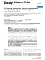
sites. Preliminary studies in our group by Mok (2005) extended the idea of boron
promotion to Co catalysts by a combination of DFT calculations and propane
decomposition experiments. Using Thermal Gravimetric Analysis (TGA), a 10 wt%
Co/γ-Al
2
O
3
catalysts promoted with 1.0 wt% boron was found to remain active
during propane decomposition, while the unpromoted reference catalyst rapidly lost
its activity as shown in Figure 1.1. Based on the success of these initial studies, a
detailed investigation was started, integrating DFT calculations, catalyst
3
characterization, and FTS reactor studies to confirm and understand the effect of
boron promotion on the stability of Co catalyst under realistic FTS conditions.
Figure 1.1. TGA profile showing the evolution of carbon deposits on boron
promoted and unpromoted Co/γ-Al
2
O
3
catalyst during propane decomposition. A 10
wt% Co/γ-Al
2
O
3
catalyst promoted with 1.0 wt% boron was found maintain its
activity much better than the unpromoted reference catalyst (Mok, 2005).
The structure of the thesis is as follows. In chapter 2, various mechanisms proposed
for FTS and for catalyst deactivation during FTS are reviewed. In chapter 3, the
computational and experimental methods used in this thesis are discussed in detail.
In chapter 4, carbon induced deactivation of Co catalyst under realistic FTS
condition is studied using a combination of DFT calculations and experimental
methods. In chapter 5, the effect of boron promotion on the stability of Co catalyst
under realistic FTS condition is elucidated, again by combining DFT and
experimental studies. Finally, the main conclusions of this work are summarized in
Chapter 6.