Exchange bias characteristic in co pd n FEMN bi layered thin films with perpendicular anisotropy and the applications for spin valves in spintronics
Bạn đang xem bản rút gọn của tài liệu. Xem và tải ngay bản đầy đủ của tài liệu tại đây (4.07 MB, 201 trang )
Exchange Bias Characteristics in [Pd/Co]
N
/FeMn Bi-layered
Thin Films with Perpendicular Anisotropy and the
Applications for Spin-Valves in Spintronics
LIN LIN
(B. Eng, National University of Singapore)
A THESIS SUBMITTED
FOR THE DEGREE OF DOCTOR OF PHILOSOPHY
DEPARTMENT OF ELECTRICAL & COMPUTER
ENGINEERING
NATIONAL UNIVERSITY OF SINGAPORE
2012
i
ACKNOWLEDGEMENTS
I would like to take this opportunity to express my sincere gratitude and
appreciation to my supervisors Assistant Professor Bae Seongtae for his kind and
consistent concern, support and guidance in the project and also all the valuable
discussion on the experimental results. His constant motivation, guidance, support and
encouragement in all aspects varying from research to personal life, have made my
candidature a truly enriching experience.
I am also grateful to be in a caring, supportive and cooperative research laboratory,
biomagnetics laboratory (BML). I thank Naganivetha Thiyagarajah, Dr. Kim
Sumwook, Dr. Joo Howan, Jeun Minhong for their support and help in this project. I
would like to thank Jiang Jing, Zhang Ping, Zeng Dinggui, Moon Seung Je, Lee
Sanghoon , Hiroshi Nakano for the valuable discussion and all the fun.
I would like to express my appreciation for all the staffs in ISML and MOS device
lab for their help in carrying out the experiments, especially to Ms. Loh Fong Leong,
Mr. Alaric Wong and Ms. Ah Lian Kiat. I would like to thank all of friends for their
supports during my Ph.D study period.
Last but not least, I would like to thank my family in China for their support, faith,
advice and patience during my whole study period.
ii
Table of Contents
ACKNOWLEDGEMENT
i
TABLE OF CONTENTS
ii
SUMMARY
vi
LIST OF FIGURES
viii
LIST OF TABLES
xv
LIST OF ABBREVIATIONS AND SYMBOLS
xvi
CHAPTER 1 INTRODUCTION
1
1.1 Background
1
1.2 Motivation and research objectives
4
1.3 Organization of thesis
6
References
9
CHAPTER 2 LITERATURE REVIEWS
13
2.1 Introduction
13
2.2 Exchange Bias
13
2.2.1 Basic phenomenon of exchange bias
13
2.2.2 Mechanism of exchange bias phenomenon
14
2.2.3 Theoretical models
16
2.2.4 Critical parameters in the exchange bias
20
2.2.5 Experimental findings
25
2.3 Perpendicular magnetic anisotropy
26
2.4 Magnetostriction and the effects of stress
29
2.4.1 Magnetostriction effect
29
2.4.2 Magnetostriction of single crystal
30
2.4.3 Physical origin of magnetostriction effect
31
2.4.4 The effect of stress on magnetization
32
2.5 Giant magnetoresistance (GMR) behavior in spin-valves
36
2.6 Summary
38
iii
References
40
CHAPTER 3 EXPERIMENTAL TECHNIQUES
48
3.1 Introduction
48
3.2 Deposition techniques
48
3.2.1 Sputtering deposition
48
3.3 Characterization techniques
51
3.3.1 Vibration sample magnetometer (VSM)
51
3.3.2 Extraordinary Hall effect measurement system (EHE)
53
3.3.3 Scanning Probe Microscopy (SPM)
53
3.3.4 Scanning electron microscope (SEM)
56
3.3.5 Transmission electron microscopy (TEM)
57
3.3.6 X-ray diffraction (XRD)
58
3.4 Summary
59
References
61
CHAPTER 4 A PHYSICAL MODEL OF EXCHANGE BIAS IN
[Pd/Co]
5
/FeMn THIN FILMS WITH PERPENDICULAR ANISOTROPY
62
4.1 Abstract
62
4.2 Introduction and motivation
63
4.3 Theoretical model
64
4.4 Sample preparation
71
4.5 Experimental validation
72
4.5.1 Physical contribution of K
AFM
×t
AFM
to the exchange bias in
[Pd/Co]
n
/FeMn PEB system: crystal and spin structure of FeMn
AFM layer
72
4.5.2 Physical contribution of K
FM,eff
×t
FM
to the exchange bias
characteristics in [Pd/Co]
5
/FeMn PEB system and its correlation
with J
ex
, and interfacial spin structure
81
4.6 Summary
93
References
94
CHAPTER 5 OPTIMIZATION OF PERPENDICULAR EXCHANGE BIAS
CHARACTERISTICS IN [Pd/Co]
5
/FeMn THIN FILM SYSTEM
97
5.1 Introduction
97
iv
5.2 The effect of the seed layer on PEB [Pd/Co]
5
/FeMn and FeMn/[Co/Pd]
5
thin films
97
5.2.1 Motivation
98
5.2.2 Sample preparation
99
5.2.3 The effect of different seed layer materials on PEB characteristics
100
5.2.4 The effect of seed layer thickness on PEB characteristics
107
5.2.5 The effect of seed layer deposition Ar pressures on PEB
characteristics
113
5.3 Study on the importance of perpendicular anisotropy to overcome the
double hysteresis behavior in [Pd/Co]
n
/FeMn thin films
120
5.3.1 Motivation
120
5.3.2 Sample preparation
120
5.3.3 The appearance of the double hysteresis behavior
121
5.3.4 The correlation between the double hysteresis and the
perpendicular anisotropy
125
5.3.5 Magnetic annealing to confirm the correlation between double
hysteresis behavior and the perpendicular anisotropy
129
5.4 Conclusion
134
References
135
CHAPTER 6 STUDY OF MAGNETOELASTIC EFFECT ON PEB
[Pd/Co]
5
/FeMn THIN FILM SYSTEM
138
6.1 Introduction
138
6.2 The effect of externally applied stress in the PEB [Pd/Co]
5
/FeMn thin
films
138
6.2.1 Motivation
139
6.2.2 Sample preparation
141
6.2.3 The magnetic properties of the PEB structures under extrinsic
stresses
142
6.2.4 Correlation between PA and stress
146
6.3 The effect of intrinsic stress in the PEB [Pd/Co]
5
/FeMn thin films
150
6.3.1 Motivation
150
6.3.2 Sample preparation
151
6.3.3 The effect of CoFe insertion thickness on the PEB characteristics
152
6.3.4 The magnetic properties of the [Pd/Co]
5
/FeMn with the CoFe
insertion layers
155
6.3.5 The effect of the surface topology on the [Pd/Co]
5
/FeMn with the
161
v
CoFe insertion layers
6.4 Conclusion
162
References
164
CHAPTER 7 PERPENDICULAR EXCHANGE BIAS CHARACTERI-
STICS APPLIED TO EXCHANGE BIASED SPIN-VALVES
166
7.1 Introduction
166
7.2 Exchange biased GMR spin valve with perpendicular anisotropy
168
References
172
CHAPTER 8 CONCLUSION
173
8.1 Overview
173
8.2 Summary of the results
174
8.3 Future work
176
References
179
List of Publications
180
vi
SUMMARY
As the demand for higher-density, higher-speed, and extremely low-dimensional
metal-based spintronic devices has grown enormously, interest in the application of
perpendicular exchange bias (PEB) to advanced spintronics devices has increased
dramatically because PEB spintronic devices have technically promising properties,
such as high thermal and magnetic stabilities and a lower device operating current
density. In contrast to the exchange bias with in-plane anisotropy that has been widely
studied, the investigation of PEB is relatively less so far. PEB continues to face the
challenge of a small exchange bias field along with a large coercivity, which limits its
applications in PEB spintronic devices. In this work, we focus on understanding the
physical origin of PEB and improving its characteristics.
First, a physical model of PEB is established based on the total energy equation
per unit area of an exchange bias system. The anisotropy energy of the
anti-ferromagnetic (AFM) layer (K
AFM
×t
AFM
) and the ferromagnetic (FM)
multi-layers (K
FM,eff
×t
FM
), as well as the interfacial exchange coupling energy (J
ex
),
were considered to be the primary physical parameters in the construction of the
physical model of the PEB phenomenon. Based on this model, it was found that
controlling the product of the perpendicular spin component of the FM and AFM
between the top layer of the perpendicular multilayers and the AFM interface, and
control of the effective anisotropy of both the AFM and FM layers are the most
crucial factors that determine the physical characteristics of the PEB. Experimental
vii
validation was achieved by investigating the magnetic reversal process before and
after magnetic annealing.
Second, experimental works have been conducted to improve the PEB
characteristics based on the established model. The effect of the seed layer on the
microstructural tailoring of the [Pd/Co]
5
/FeMn thin film has been studied by
modifying the deposition conditions of the different seed layer materials. It was
observed that a smooth interface with fine nucleation sites could significantly improve
the PEB characteristics of the [Pd/Co]
5
/FeMn structure. Experimental works
investigating the physical origin of the undesirable double hysteresis behavior in the
PEB system have also been performed. A large perpendicular anisotropy has been
identified as the key to eliminating this behavior.
Third, this thesis explores the effect of stress on the PEB characteristics by
controlling the stress of the PEB multilayers externally and internally.
Magnetoelastically induced perpendicular anisotropy (K
FM,me
) and J
ex
in the system
have been effectively controlled to improve the PEB characteristics significantly.
Finally, the theoretical and experimental results are implemented in the design of a
PEB GMR spin valve device. The exchange-biased GMR spin valve devices with
PEB bi-layered thin films exhibit high levels of magnetic stability and GMR
performance.
viii
List of Figures
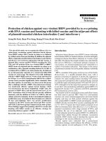
Figure 1.1
Hysteresis loop, m(H), of a FeF2/Fe bilayer at T=10K after field
cooling. The exchange bias field, H
E
, and the coercivity, H
c
, are
indicated in the figure.
2
Figure 2.1
Hysteresis loop of the samples with the structure of
substrate/Ta/[Pd/Co]
5
/FeMn/Ta
14
Figure 2.2
Schematic diagram of the spin configuration of an F-AF bilayer
(a) at different stages (i)-
(v) of an exchange biased hysteresis
loop (b). Note that the spin configurations are just a simple
cartoon to illustr
ate the effect of the coupling and they are not
necessarily accurate portraits of the actual rotation of the FM or
AFM magnetizations.
16
Figure 2.3
Schematic diagram of angles involved in an exchange bias
system
18
Figure 2.4
Schematic of the ideal FM/AFM interface. The FM and AFM
layers are single crystal and epitaxial with an atomically smooth
interface. The interfacial AFM spin plane is a fully
uncompensated spin plane. For this ideal interface, the
calculated value of the full interfacial ene
rgy density is about
two orders of magnitude larger than the experimentally observed
values.
20
Figure 2.5
Interfacial complexities of a polycrystalline
FM(metal)/AFM(oxide) interface. In this figure, the interfacial
spins prefer to align ferromagnetically. The X marks identify the
frustrated exchange bonds, i.e. the interfacial spins that are
coupled antiferromagnetically. The interfacial region can have a
high degree of stress since metals and oxides often have very
different lattice parameters. Dislocations (represented by the
dashed line) can form during film growth to relieve the stress.
20
Figure 2.6
Dependence of exchange bias Hex with the AFM layer thickness
for FeNi/FeMn at a fixed t
FM
= 7nm.
23
Figure 2.7
Magnetic-force microscopy images for the in-plane
magnetization 40-nm-thick 0.5
mm x 0.5 mm square NiFe
element (top) and perpendicular magnetization 100-nm-thick
square GdFe/ FeCo elements; 0.5 mmx0.5 mm, and 0.3 mmx0.3
29
ix
mm (bottom) at zero field.
Figure 2.8
Magnetostriction of an iron crystal in the [100] direction
31
Figure 2.9
Mechanism of magnetostriction
32
Figure 2.10
Effect of applied tensile (+) and compressive (-) stress on the
magnetization of nickel.
33
Figure 2.11
Effect of tension on the magnetization of a material with positive
magnetostriction (λ > 0)
33
Figure 2.12
Magnetoresistance of Fe/Cr superlattices. Both the current and
the applied field are along the same [110] axis in the film plane.
36
Figure 2.13
Schematic of resistor model for GMR effect in (a) parallel, and
(b) antiparallel configurations
37
Figure 3.1
Schematic illustration of a sputtering chamber and sputtering
process
49
Figure 3.2
(a) EV5 VSM (b) A schematic illustration of a typical VSM
52
Figure 3.3
(a) Digital Instrument
TM
3100 SPM system (b) A schematic of a
typical atomic force microscopy measurement
55
Figure 3.4
Schematic of the sample-electron interaction
56
Figure 3.5
Different imaging techniques used in TEM. (a) Bright field, (b)
Dark field and (c) Multiple beam interference imaging.
58
Figure 4.1.
Cross-sectional view of a [Pd/Co]5/FeMn thin film structure
63
Figure 4.2.
(a) Schematic diagram of angles and magnetizations involved in
a PEB system. Note that the AFM and FM anisotropy axes are
assumed collinear (b) FeMn 3Q sub-lattice spin structure
65
Figure 4.3
M-H loops of [Pd/Co]5/Ta multilayers where the magnetic field
is applied alone in-
plane (white) and perpendicular (black)
direction of the thin film.
70
x
Figure 4.4
Hysteresis loops (M-H loops) of as-deposited (a)
Si/Ta(2)/[Pd(0.6)/Co(0.23 nm)]
5
/Ta multi-layered thin films, (b)
Si/Ta(2)/FeMn(11.6)/[Co(0.23)/Pd(0.6 nm)]
5
/Ta, and (c)
Si/Ta(2)/[Pd(0.6)/Co(0.23)]
5
/FeMn(11.6 nm)/Ta exchange
biased thin films with perpendicular anisotropy.
73
Figure 4.5.
XRD patterns of as-deposited
Si/Ta(2)/FeMn(11.6)/[Co(0.23)/Pd(0.6 nm)]
5
/Ta (“bottom
structure”)
and Si/Ta(2)/[Pd(0.6)/Co(0.23)]
5
/FeMn(11.6 nm)/Ta
(“top structure”) exchange biased thin films with perpendicular
anisotropy.
75
Figure 4.6
XTEM images, SAED patterns, and Fourier transform images of
as-deposited (a) Si/Ta(2)/[Pd(0.6)/Co(0.23)]
5
/FeMn(11.6 nm)/Ta
(“top structure”), and Si/Ta(2)/FeMn(11.6)/[Co(0.23)/Pd(0.6
nm)]
5
/Ta (“bottom structure”).
77
Figure 4.7
Spin configuration of γ-phase FeMn with 3 Q structure: (a) a
unit cell, (b) a (111) plane and (c) Co/FeMn interface in
Si/Ta(2)/[Pd(0.6)/Co(0.23)]
5
/FeMn(11.6 nm)/Ta (“top
structure”) exchange biased thin films.
79
Figure 4.8
Hysteresis loops of (a) (a) Si/Ta(2)/[Pd(0.6)/Co(0.23 nm)]
5
/Ta
multi-layered thin films, (b)
Si/Ta(2)/FeMn(11.6)/[Co(0.23)/Pd(0.6 nm)]
5
/Ta, (c)
Si/Ta(2)/[Pd(0.6)/Co(0.23)]
5
/FeMn(11.6 nm)/Ta exchange
biased thin films before and after annealing at the fixed
temperature of 240 °C with a field of either 1.2 or 3.3 kOe
applied along the perpendicular to the film direction, and (d) a
schematic diagram illustrating the spin configuration of
Si/Ta(2)/[Pd(0.6)/Co(0.23)]
5
/FeMn(11.6 nm)/Ta exchange
biased thin films before and after annealing with different
magnetic fields perpendicular to the film direction.
(e) and (f)
Perpendicular and in-plane M-
H loops of
Si/Ta(2)/[Pd(0.6)/Co(0.23)]
5
/FeMn(11.6 nm)/Ta exchange
biased thin films before and after annealing at 3.3 kOe
83
Figure 4.9
XRD patterns of Si/Ta(2)/[Pd(0.6)/Co(0.23)]
5
/FeMn(11.6
nm)/Ta exchange biased thin films before and after annealing at
the fixed temperature of 240 °
C with a magnetic field applied
along the perpendicular or in-plane to the film direction.
87
Figure 4.10
Hysteresis loops of (a) Si/Ta(2)/[Pd(0.6)/Co(0.23 nm)]
5
/Ta
multi-layered thin films, (b)
Si/Ta(2)/FeMn(11.6)/[Co(0.23)/Pd(0.6 nm)]
5
/Ta, (c)
Si/Ta(2)/[Pd(0.6)/Co(0.23)]
5
/FeMn(11.6 nm)/Ta exchange
88
xi
biased thin films before and after annealing at the fixed
temperature of 240 °C with a magnetic field of either 0.7 or 2.2
kOe applied along the in-
plane to the film direction, and (d)
hysteresis loop of Si/Ta(2)/[Pd(0.6)/Co(0.23)]
5
/FeMn(11.6
nm)/Ta (after annealed with a magnetic field of 2.2 kOe)
measured under the applied magnetic filed along the in-plane
direction, and (e) a schematic diagram illustrating the spin
configuration of Si/Ta(2)/[Pd(0.6)/Co(0.23)]
5
/FeMn(11.6
nm)/Ta exchange biased thin films before and after annealing
with different magnetic fields applied along the in-plane
direction.
Figure 4.11
Hysteresis loops of Si/Ta(2)/[Pd(0.6)/Co(0.23 nm)]
5
/Ta multi-
layered thin films with perpendicular anisotropy (“PML”)
,
Si/Ta(2)/FeMn(11.6)/[Co(0.23)/Pd(0.6 nm)]
5
/Ta (“bottom
structure”), and Si/Ta(2)/[Pd(0.6)/Co(0.23)]
5
/FeMn(11.6 nm)/Ta
(“top structure”) exchange biased thin films before and after
annealing at the fixed temperature of 100
°
C with different
applied magnetic fields and directions: (a) “PML” with
perpendicular magnetic field, (b) “bottom structure” with
perpendicular magnetic field, (c) “top structure” with
perpendicular magnetic field, (d) PML with in
-
plane magnetic
field, (b) “bottom structure” with in
-plane magnetic field, (c) “top
structure” with in-plane magnetic field.
92
Figure 5.1
Hysteresis loops (M-H loops) of (a) Si/Seed
layer/[Pd(1.2)/Co(0.3)]
5
/FeMn(12)/Pd(2 nm) and (b) Si/Seed
layer/FeMn(12)/[Co(0.3)/Pd(1.2)]
5
/Pd(2 nm) PEB thin films for
seed layer of Ta, Pd and Cu
100
Figure 5.2
XRD pattern of Si Si/Seed
layer/[Pd(1.2)/Co(0.3)]
5
/FeMn(12)/Pd(2 nm) exch
ange biased
thin films with perpendicular anisotropy for seed layer of (a) Ta,
(b) Pd and (c) Cu, Si/Seed
layer/FeMn(12)/[Co(0.3)/Pd(1.2)]
5
/Pd(2 nm) PEB thin films for
seed layer of (d) Ta, (e) Pd and (f) Cu
102
Figure 5.3
XTEM images of (a) Si/Ta/[Pd(1.2)/Co(0.3)]
5
/FeMn(12)/Pd(2
nm) PEB multilayers and Si/Seed
layer/FeMn(12)/[Co(0.3)/Pd(1.2)]
5
/Pd(2 nm) PEB thin films for
seed layer of (b) Ta, (c) Pd and (d) Cu
104
Figure 5.4
Dependence of H
c
, H
ex
and K
FM,eff
on different seed layer
thickness for
(a) Si/Ta(2–7.5)/[Pd(1.2)/Co(0.3)]
5
/FeMn(12)/Pd(2
nm) and (b) Si/Pd(2
-5)/[Pd(1.2)/Co(0.3)]
5
/FeMn(12) /Pd(2 nm)
and (c) Si/Cu(2-7)/[Pd(1.2)/ Co(0.3)]
5
/FeMn(12)/Pd(2 nm) PEB
108
xii
thin films
Figure 5.5
Dependence of roughness on different seed layer thickness for (a)
Si/Ta(2
- 7.5)/[Pd(1.2)/Co(0.3)]
5
/FeMn(12)/Ta
(2 nm) and (b)
Si/Pd(2
-5)/[Pd(1.2)/Co(0.3)]
5
/FeMn(12)/Ta(2 nm) and (c) Si/Cu(2
-
7)/[Pd(1.2)/Co(0.3)]
5
/FeMn(12)/Ta(2 nm) PEB thin films
110
Figure 5.6
XRD patterns of the Si/Ta(2-
7.5)/[Pd(1.2)/Co(0.3)]
5
/FeMn(12)/Pd(2 nm) PEB thin films
112
Figure 5.7
Dependence of H
c
, H
ex
and K
FM,eff
on different seed layer Ar
pressure for (a) Si/Ta(3)/[Pd(1.2)/Co(0.3)]
5
/FeMn(12)/Pd(2 nm)
and (b) Si/Pd(4)/[Pd(1.2)/Co(0.3)]
5
/FeMn(12)/Pd(2 nm) and (c)
Si/Cu(5)/[Pd(1.2)/Co(0.3)]
5
/FeMn(12)/Pd(2 nm) PEB thin films
115
Figure 5.8
AFM results for Si/Ta(3)/[Pd(1.2)/Co(0.3)]
5
/FeMn(12)/Pd(2 nm)
PEB thin films with Ta deposited at (a) 2 mTorr and (b) 10 mTorr
117
Figure 5.9
XRD patterns of Si/Ta(3)/[Pd(1.2)/Co(0.3)]
5
/FeMn(12)/Pd(2 nm)
PEB thin films for different Ar pressure of Ta seed layer
118
Figure 5.10
M-H loops of the perpendicularly magnetized Ta(2.1)/[Pd(0.6)/
Co(
t)]
5
/FeMn(11.6)/Ta(2.1 nm) exchange biased thin films with
different Co layer thickness.
123
Figure 5.11
XRD patterns of the perpendicularly magnetized Ta(2.1)/
[Pd(0.6)/Co(
t)]
5
/FeMn(11.6)/Ta(2.1 nm) exchange biased thin
films with different Co layer thickness.
124
Figure 5.12
(a) Calculated in-plane tensile stress, and (b) effective
perpendicular anisotropy energy of the perpendicularly magnetized
Ta(2.1)/ [Pd(0.6)/Co(
t)]
n
/FeMn(11.6)/Ta(2.1 nm) exchange biased
thin films with different Co layer thickness and the number of bi-
layers.
126
Figure 5.13
(a) H
ex
of the Ta(2.1)/[Pd(0.6)/Co(t)]
n
/FeMn(11.6)/Ta(2.1 nm)
exchange bias thin films with different Co layer thickness and the
number of bi
-
layers measured under the externally applied
magnetic field both along the perpendicular (solid mark) and the
parallel (open mark) to the fil
m plane. (b), and (c) shows the M-
H
loops of the Ta(2.1)/[Pd(0.6)/Co(0.76)]
n
/ FeMn(11.6)/Ta(2.1 nm)
exchange biased thin films with number of bi
-
layers of n=4 and
n=5, respectively.
128
Figure 5.14
Effects of magnetic annealing on the exchange bias characteristics
in the perpendicularly magnetized
130
xiii
Ta(2.1)/[Pd(0.6)/Co(0.61)]
n
/FeMn(11.6)/ Ta(2.1 nm) thin films
with different number of bi
-
layers and with different annealing
temperature at the fixed magnetic field of 3.3 kOe. (a) n=4, (b)
n=5, and (c) n=6,
respectively. (d) shows the calculated effective
perpendicular anisotropy energy obtained from the perpendicularly
magnetized Ta(2.1)/[Pd(0.6)/Co(
t)]
5
/FeMn(11.6)/Ta(2.1 nm) thin
films with different Co thickness annealed at the different
temperatures.
Figure 5.15
(a) MFM images of the Ta(2.1)/[Pd(0.6)/Co(0.61)]
4
/FeMn(11.6)/
Ta(2.1 nm) thin films with (a) as
-
grown and (b) after annealed at
240 °C with a 3.3 kOe of magnetic field applied perpendicular to
the film plane.
132
Figure 6.1
External stress applied to the sample by a specially designed
bending apparatus. (a) Standby mode, where no stress is applied,
(b) the sample is subjected to a tensile stress when the platform is
bending down; (c) the sample is subjected to a compress stress
when the platform is bending up
141
Figure 6.2
(a) The variation of coercivity, exchange bias field and lattice
constant according to applied tensile/compressive stress and the
M
-H loops of [Pd(0.6)/Co(0.23)]
5
/FeMn(10.8 ㎚) thin films with
different (b) tensile and (c) compressive stress.
143
Figure 6.3
XRD patterns of exchange biased [Pd(0.6)/Co(0.23)]
5
/FeMn(10.8
㎚
) thin films under the
mechanically applied tensile and
compressive stress.
147
Figure 6.4
AFM surface roughness results of the
[
Pd(0.6)/Co(0.23)]
5
/FeMn(10.8 ㎚)
thin films before and after
externally applied tensile/compressive stress.
148
Figure 6.5
The MFM images of (a) No stress,
[Pd(0.6)/Co(0.23)]
5
/FeMn(10.8 ㎚) thin films, (b) 3.87 x 10
-1
of
tensile stress,
[Pd(0.6)/Co(0.23)]
5
/FeMn(10.8 ㎚) thin films
, (c)
No stress,
[Co(0.9)/Pd(0.6 ㎚)]
5
multi-layers, and (d) 3.87 x 10
-1
of
tensile stress, [Co(0.9)/Pd(0.6
㎚
)]
5
multi-layers.
149
Figure 6.6
Dependence of (a) Hex, Hc and (b) (Hex – Hc) on the Co
80
Fe
20
insertion layer thickness in Ta(2.1 nm)/[Pd(0.6 nm)/Co(0.27
nm)]
5
/Co
80
Fe
20
(t nm)/FeMn(10.7 nm)/Ta(2.1 nm) exchange
biased multilayers.
152
Figure 6.7
The normalized EHE loops of
154
xiv
Ta(2.1)/[Pd(0.6)/Co(0.23)]
5
/CoFe(t)/FeMn(11.6)/Ta(2.1 nm) PEB
thin films
without and with
different CoFe insertion layers and
thickness: (a)
Co
80
Fe
20
, t = 0.6, (b) Co
80
Fe
20
t = 0.4, (c) Co
90
Fe
10
t
= 0.6, and (d) Co
90
Fe
10
t = 0.4, with P
Ar,CoFe
of 3, 5, and 10 mTorr
Figure 6.8
Dependence of (a) H
ex
and (b) H
c
of
Ta(2.1)/[Pd(0.6)/Co(0.23)]
5
/Co
80
Fe
20
or Co
90
Fe
1
0
(0.6)/FeMn(11.6)/Ta(2.1 nm) PEB thin films on the P
Ar,CoFe
.
158
Figure 6.9
(a) Dependence of film resistivity of
Ta(2.1)/[Pd(0.6)/Co(0.23)]
5
/Co
80
Fe
20
or Co
90
Fe
1
0
(
0.6)/FeMn(11.6)/Ta(2.1 nm) PEB thin films and
single layered
Co
80
Fe
20
(20 nm) thin films on P
Ar,CoFe
, and (b) XRD patterns of 2
0
nm
Co
80
Fe
20
single layered thin films deposited at
different
P
Ar,CoFe
varied from 1.7 to 20 mTorr.
159
Figure 6.10
Ex-AFM images of Ta(2.1)/[Pd(0.6)/Co(0.23)]
5
/
Co
80
Fe
20
(0.6)/FeMn(11.6)/Ta(2.1 nm) PEB
thin films with
Co
80
Fe
20
insertion deposited at P
Ar,CoFe
of (a) 1.7 and (b)
20
mTorr.
161
Figure 7.1
Schematics of M
–
H (a) and MR
–
H (b) curves of a typical spin
valve (H
ex
: exchange-bias field; H
in
: interlayer coupling field
between free and pinned layer; (H
FL
c1
− H
FL
c2
): coercivity of
free layer; (H
PL
c1
−
H
PL
c2
): oercivity of pinned layer)
166
Figure 7.2
M-H (a) and GMR (b) curves of the PEB GMR spin valve with
the structure of
Ta(2.0
nm)/[Pd(0.6
)/Co(0.23)]
2
/Pd(0.6)/Co(0.96)/Cu(2.3)/Co(1.4)/[Pd(0.
6)/Co(0.23)]
4
/FeMn(10.6)/Ta(2.0)
168
Figure 8.1
H
ex
vs. temperature for different AFM materials spin valves
178
xv
List of Tables
Table 3.1
The sputtering condition and sputtering rate for various materials
used in this thesis
51
xvi
LIST OF ABBREVIATIONS AND SYMBOLS
a
0
lattice constant
AFM
antiferromagnetic
D
AFM
domain size of the AFM layer
EBL
EBSV
EHE
electron beam lithography
exchange biased spin-valves
extraordinary Hall Effects
FM
ferromagnetic
GMR
giant magnetoresistance
H
ex
exchange bias field
H
c
coercivity field
H
FM
applied field
H
k
anisotropy field
HDD
hard disk drive
J
ex
interfacial exchange coupling energy
J
INT
interface coupling constant
K
AFM
antiferromagnetic anisotropy constant
K
FM,bulk
bulk anisotropy
K
FM,surface
surface anisotropy
K
FM,crystalline
crystalline anisotropy
k
s
surface anisotropy constant
K
FM
ferromagnetic anisotropy constant
K
FM,me
magnetoelastically induced perpendicular anisotropy constant
M
FM
ferromagnetic saturation magnetization
M
AFM
uncompensated moment/unit area of the interface
ME
MEMS
MFM
MLs
magneto-elastic
microelectromechanical systems
magnetic force microscope
multilayers
xvii
MO
MR
magneto-optical
magnetoresistance
MRAM
magnetic random access memory
MTJ
P
Ar,CoFe
PA
magnetic tunnel junction
Ar sputtering gas pressures
perpendicular anisotropy
PEB
perpendicular exchange bias
PMA
PML
perpendicular magnetic anisotropy
perpendicular multilayers
PVD
physical vapour deposition
ρ
bending curvature
λ
magnetostriction coefficient
RE
σ
S
AFM
S
FM
SAED
rare earth
stress component
unit spin vectors of AFM layers
unit spin vectors of FM layers
selected area electron diffraction
SEM
SNR
STS
SPM
scanning electron microscopy
signal-to-noise ratio
spin transfer switching
Scanning Probe Microscopy
SV
spin-valve
t
AFM
Antiferromagnetic layer thickness
t
FM
ferromagnetic layer thickness
T
N
Neel temperature
T
C
Curie temperature
TEM
tunneling electron microscopy
TMR
TEM
tunneling magnetoresistance
transmission electron microscopy
v
Poisson’s ratio
VSM
vibrating sample magnetometer
xviii
XRD
X-ray diffraction
CHAPTER 1 INTRODUCTION
1
CHAPTER 1 INTRODUCTION
1.1 Background
Exchange-biased giant magnetoresistance (GMR) spin-valves with perpendicular
anisotropy have recently attracted dramatically increased interest because of their
applications in spintronics devices, such as in spin transfer switching (STS), magnetic
random access memory (MRAM), ultra-high-density magnetic information devices,
and low-field-detection spin oscillators.
1 - 4
Interest in these applications is mainly
driven by the fact that exchange-biased spin-valves with perpendicular anisotropy
promise technical advantages, such as high thermal and magnetic stability and lower
device-operating current density.
5 - 9
Such outstanding properties allow the realization
of extremely low-dimensional and high-reliability devices in more advanced
spintronics applications than their in-plane anisotropy counterparts.
1 - 9
The stability
of these devices, which is one of the critical factors determining the performance of
GMR spin-valves, is achieved by a large exchange coupling that inhibits magnetic
excitation in the pinned layer of the GMR spin-valve and guarantees reproducible
write/read. This property becomes even more critical in patterned devices in which
there is a distribution of the switching field. Therefore, the understanding of the
exchange bias phenomenon and improvement of the exchange bias characteristics are
critical for the development of GMR spin valves for application to spintronic devices.
Exchange bias was first reported by Meiklejohn and Bean (M-B) in 1956 as an
exchange anisotropy. “This anisotropy is the result of an interaction between an
antiferromagnetic material and a ferromagnetic material”.
10 - 12
With extensive studies
CHAPTER 1 INTRODUCTION
2
on exchange bias, this phenomenon has been confirmed to originate from the
unidirectional anisotropy, which is a result of the interfacial exchange interaction
between ferromagnetic (FM) and anti-ferromagnetic (AFM) materials.
10- 13
The
localized uncompensated AFM spins, which are coupled to FM spins at the interface,
exert a strong torque to pin the FM spins and prevent them from switching under an
external field. As illustrated in Figure 1.1, this behavior typically exhibits a shift in the
hysteresis loop along the magnetic field axis (exchange coupling field, H
ex
), as well
as an increase in the half-width of the loop (coercivity, H
c
).
Figure 1.1 Hysteresis loop, m(H), of a FeF
2
/Fe bilayer at T=10K
after field cooling.
14
The exchange bias field, H
ex
, and the
coercivity, H
c
, are indicated in the figure.
Exchange bias has been observed in many different systems containing
FM-AFM interfaces, such as small particles,
15 - 18
inhomogeneous materials,
19, 20, 21
FM films on AFM single crystals
22, 23
and polycrystalline thin films.
24, 25, 26
The
CHAPTER 1 INTRODUCTION
3
primary focus of this thesis is layered polycrystalline AFM-FM because it offers
improved control over the interface, and it is more amenable to the development of
spintronic devices. The exchange bias phenomenon is explained well by Fulcomer
and Charap’s model and its extensions in many polycrystalline FM-AFM exchange
bias coupled system with in-plane anisotropy. These models assume that the
magnetization of each region in the FM layer behaves coherently and couples with
multiple AFM grains. The interface net moment of the AFM grains (S
net
) arises from
the atomic roughness or defects of the AFM surface. The effect of annealing on S
net
has been attributed to the thermally assisted switching of the AFM-grains,
27
the phase
change of AFM-grains,
28
the change of the AFM-anisotropy through lattice
distortion,
29
or an interface vacancy relocation mechanism.
30
Since their discovery, exchange bias effects have been widely used in many
applications, including permanent magnets,
31
magnetic recording media,
32, 33
and
domain stabilizers in recording heads based on anisotropic magnetoresistance
34
.
Since the 1990s, increased interest in these phenomena
35
has arisen because of the
reduction of the saturation fields required to observe GMR in exchange-biased
systems
36
compared to that required in standard GMR multilayer systems
37
. The
exchange-bias phenomenon has become the basis for an important application in
information storage technology, and it is the subject of intensive world-wide research
and development activities.
For most FM/AFM bilayers, the exchange bias is observed with in-plane
anisotropy because this is usually the easy axis of the FM layer due to the strong
CHAPTER 1 INTRODUCTION
4
shape anisotropy. However, exchange bias effects have also recently been induced
along the perpendicular-to-film direction in both continuous and nanostructured
multilayers. Exchange bias with perpendicular anisotropy was first discovered in the
FeF
2
-CoPt heterogeneous structured system in 2000.
38
Since then, an increasing
number of research activities have begun to physically clarify this uncertain exchange
bias phenomenon. The perpendicular magnetic phenomenon is promising for
spintronic applications in magnetic sensors based on spin valves or magnetic tunnel
junction structures because it offers high thermal and magnetic stabilities and a lower
device operating current density.
39, 40
In this thesis work, a perpendicular exchange bias study was conducted using the
[Pd/Co]n/FeMn multilayer thin film system. FeMn was chosen as the AFM layer for
this study because FeMn is a well-known AFM material. Providing considerable
fundamental information for this thesis study, many research works have studied this
material, such as the FeMn magnetic phase information, crystal structure, Neel
temperature, and spin structure. The [Pd/Co] bilayered structure was chosen in this
thesis work because this is one of the promising candidate materials that has large
perpendicular anisotropy. In addition, the perpendicular anisotropy can be controlled
easily by varying the thickness of the Pd or Co, as well as by changing the number of
bilayers.
41 - 44
1.2 Motivation and research objectives
The perpendicular exchange bias (PEB) has attracted significant attention because
CHAPTER 1 INTRODUCTION
5
of its advantages over the in-plane system; however, it faces challenges, such as a
small exchange bias field (H
ex
) with a large coercivity (H
c
). The resulting poor
stability limits its applicability to a variety of spintronics devices.
Current research efforts relevant to PEB have mainly focused on the development
of new metallic thin film PEB systems
45 - 48
and the improvement of PEB
characteristics for advanced spintronics.
49-51
Unlike the in-plane anisotropy systems,
in which the exchange bias mechanism is already well-understood,
52 - 54
current
studies of PEB are primarily focused on empirical methods.
45-51
Despite the
investment of significant research efforts, the lack of well-established physical models
has already become a major bottleneck in overcoming the scientific challenges of this
system. Therefore, the development of a physical model for a PEB system that can
elucidate the underlying physics and predict the physical parameters that can
influence the adjustment of the PEB characteristics more effectively is the most
urgent issue for rapid extension of the application of PEB to a wider range of
spintronic devices.
To understand the underlying physics of the PEB system, a physical model of
PEB is established in this work. The anisotropy energy of the AFM layer
(K
AFM
×t
AFM
), that of the FM multi-layers (K
FM,eff
×t
FM
, where K
AFM
and K
FM,eff
are
the anisotropy constant of AFM and FM layers, and t
AFM
and t
FM
are the total thin
film thickness of AFM and FM layers, respectively) and the interfacial exchange
coupling energy (J
ex
) were considered to be the primary physical parameters for the
construction of the physical model of PEB phenomenon. Based on the established
CHAPTER 1 INTRODUCTION
6
model, it was found that controlling the product of the perpendicular magnetization
component between the top layer of the perpendicular multilayers (PMLs) and the
AFM interface, as well as the effective anisotropy of both the AFM and FM layers, is
the most crucial factor that determines the physical characteristics of the PEB.
55
To improve the PEB characteristics, experiments have been conducted to
optimize the PEB multilayer structure and understand the physical origin of the
undesired appearance of a double hysteresis loop based on the established model. The
optimization includes varying the seed layer materials and deposition conditions,
modifying the [Co/Pd]
n
ferromagnetic multilayer structures, and controlling the
magnetic annealing conditions.
The magnetoelastic effect on the PEB characteristics has also been explored by
controlling K
FM,eff
, as well as J
ex
. This was achieved by tailoring the stress-induced
perpendicular anisotropy, which is considered to be another crucial physical origin of
the perpendicular anisotropy
of the [Co/Pd] PMLs
56
. These methods have proven
effective for improving the PEB characteristics. Finally, changes based on the
theoretical and experimental results were implemented to develop exchange-biased
GMR spin valve device with PEB bilayered thin films that exhibit high magnetic
stability, as well as high GMR performance.
1.3 Organization of thesis
Chapter 1 discusses the background, motivation and objective of the work
presented in this thesis.