Processing structure property relationship in electrospun polymer nanofibers
Bạn đang xem bản rút gọn của tài liệu. Xem và tải ngay bản đầy đủ của tài liệu tại đây (7.72 MB, 175 trang )
PROCESSING-STRUCTURE-PROPERTY RELATIONSHIP
IN
ELECTROSPUN POLYMER NANOFIBERS
RYUJI INAI
(M. Eng), KIT
A THESIS SUBMITTED
FOR THE DEGREE OF Ph.D. OF ENGINEERING
DEPARTMENT OF MECHANICAL ENGINEERING
NATIONAL UNIVERSITY OF SINGAPORE
2007
i
ACKNOWLEDGEMENT
I would like to express my deep gratitude and great respect to my supervisor, Prof.
Seeram Ramakrishna, for his inspiration and encouragement during my Ph.D. study.
I also greatly appreciate the discussions and guidance from my co-supervisor, Dr.
Chan Kwan-Ho, Casey. I am deeply grateful to Prof. Masaya Kotaki for his valuable
discussions and support.
Special thanks are given to Dr Kazutoshi Fujihara, Chan Kok Ho Kent and Tan Si
Hui for their instructions with the experimental supports. Throughout my study, I
have greatly benefited from working with my colleagues-
Dr. Thomas Yong, Dr. Ma
Zuwei, Teo Wee Eong, Renuga Gopal, Satinderpal Kaur, Teo Chieh Yin Karen, Wang
Yanping Karen, He Wei and Ramakrishnan Ramaseshan. To Steffen Ng and Kelly
Low Puay Joo for handling all administrative work related to this thesis.
Their
friendship and unconditional support will always be remembered. I wish them the
best in all their future endeavors. Finally, I would like to show my appreciation to
my wife and parents. Thanks to their love and kindest supports, I could overcome
the facing problems and complete Ph.D. study.
ii
Table of Contents
Acknowledgements i
Table of Contents ii
Summary vi
List of Tables x
List of Figures xii
List of Publications xvii
Chapter I INTRODUCTION
1
Chapter II Literature Review
5
2-1. Overview of Polymer Micronfibers
5
2-1-1. Melt-spinning Process
5
2-1-2. Solution-spinning Process
7
2-1-3. Post-drawing Process
7
2-1-4. Structure Formation during Processing
9
2-1-5. Structure-Property Relationship
13
2-2. Overview of PLLA Micronfibers
17
2-2-1. Processing-related Parameters Effects on Molecular Structure of
PLLA Fibers
17
2-2-2. Structure Formation of PLLA Fibers
19
2-2-3. Structure-property Relationship of PLLA Fibers
20
2-3. Polymer Nanofibers
22
2-3-1. Processing of Polymer Nanofibers
22
2-3-2. Processing-Fiber Morphology Relationship
24
2-3-3. Processing-Molecular Structure Relationship
33
2-3-4. Structure-Property Relationship
34
iii
Chapter III FIBER MORPHOLOGY OF ELECTROSPUN
POLYMER FIBERS AND THEIR
ARCHITECTURE
36
3-1. Introduction
36
3-2. Experimental
38
3-2-1. Design of Electrospinning Setup
40
3-2-2. Materials Selection
41
3-2-3. Control of Humidity Level
41
3-2-4. Conductivity Meter and Rheometer
41
3-2-5. Scanning Electron Microscopy (SEM) and Transmission
Electron Microscopy (TEM)
42
3-3. Results and Discussion
42
3-3-1. Fiber Morphology
42
(1) Solution Properties Effect
42
(2) Processing Conditions Effect
49
(3) Ambient Conditions Effect
53
(4) Processing Map
57
(5) Electrospinning of Ultra-fine Polymer Fibers
60
3-3-2. Fibers Patterning
60
(1) Effect of Table Material
60
(2) Effect of Take-up Velocity
63
(3) Electrospinning of 3-D architecture with aligned
nanofibers
64
3-4. Summary
65
Chapter IV
STRUCTURE AND PROPERTIES OF AS-SPUN
FIBERS
67
4-1. Introduction
67
4-2. Experimental
69
iv
4-2-1. Materials
69
4-2-2. Solvent-cast Film
70
4-2-3. Annealing
71
4-2-4. X-ray Diffraction (XRD)
71
4-2-5. Differential Scanning Calorimetry (DSC)
71
4-2-6. Tensile Test of Electrospun Nanofiber Membranes
72
4-2-7. Tensile Test of Electrospun Single Nanofibers
73
4-3. Results
75
4-3-1. Evaluation of Tensile Test Method using Nanofiber Membranes
75
4-3-2. As-spun PLLA Nanofibers
79
4-3-3. As-spun PCL Nanofibers
94
4-3-4. As-spun P(LLA-r-CL) Copolymer Nanofibers
99
4-4. Discussion
102
4-5. Summary
106
Chapter V STRUCTURE AND PROPERTIES OF
ELECTROSPUN FIBERS VIA POST-
PROCESSING
109
5-1. Introduction
109
5-2. Experimental
110
5-2-1. Material Selection
110
5-2-2. Post-processing
111
5-2-3. Tensile Test of Electrospun Single Nanofibers
114
5-3. Results
114
5-3-1. Annealing Effects
114
5-3-2. Hot-drawing Effects
118
5-4. Discussion
128
v
5-5. Summary
137
Chapter VI CONCLUDING REMARKS AND
RECOMMENDATIONS
140
6-1. Summary and Results
140
6-2. Review of Contributions
145
6-3. Recommendations for Future Works
146
6-4. Conclusion
148
REFERENCES 149
vi
SUMMARY
In this study, processing-structure-properties relationship in electrospun
biodegradable polymer nanofibers was investigated. In order to study the
relationship, an electrospinning setup was designed and developed (chap. 3). Unlike
the standard setup, ambient conditions can be controlled using the developed setup.
The purpose in the first part of the work (processing studies) was to discuss the
effects of electrospinning parameters on electrospun fiber morphology (fiber
diameter and fiber uniformity). It was found that electrospun fiber diameter is
determined by mass of polymer in the spinning jet and the jet drawing ratio. The
tendencies to change fiber morphology were summarized in the processing map.
Based on the systematic parameter studies, polymer nanofibers as small as 9nm in
diameter were successfully produced. With the electrospinning setup developed in
this study, 2D and 3D structures with electrospun aligned nanofibers were
successfully produced (Chap. 3).
Structure formation / development in electrospun nanofibers were discussed using
semi-crystalline rigid (PLLA), ductile (PCL) homopolymers and their block and
vii
random copolymers (Chap. 4). XRD and DSC analysis were conducted to
investigate processing condition effects on the molecular structure.
For electrospun rigid polymer (PLLA) nanofibers, parameters which contribute to an
electrical drawing of a jet, were found to affect molecular structure in amorphous
region. Parameter which is associated with the mechanical drawing of the jet was the
dominant parameter to develop crystalline structure. On the other hand, crystalline
structure was developed in electrospun ductile polymer (PCL) nanofibers via
electrospinning process, but the crystallinity was independent of processing
parameters. Structure formation of electrospun nanofibers seems to be dependent on
polymer properties.
It was found that structure development of rigid (- LLA) units and ductile (- CL) is
different in their block and random copolymers. Crystalline structure attributed to
rigid (- LLA) units was developed in random units sequence (P(LLA-r-CL))
copolymer, while ductile (- CL) units were transformed into crystalline structure in
block units sequence (P(LLA-b-CL) copolymer. The structure formation of ductile
or rigid units is highly reflected by their mobility.
viii
A disc collector was developed to conduct tensile tests using electrospun single
nanofibers. As the results of tensile tests, crystallized PLLA nanofibers showed
higher tensile modulus, strength but lower strain at break than that of amorphous
PLLA nanofibers.
To further study structure formation of polymer nanofibers, post-processing was
applied to the as-spun PLLA nanofibers. Based on XRD and DSC analysis, the
model of structure formation in hot-drawn nanofibers was suggested. The results of
structure analysis indicated that crystalline formation via post-processing is highly
dependent on initial molecular structure before the post-processing. Via annealing
process, amorphous fibers have a high potential for the development of highly
crystallized structure which is corresponding to isotropic crystalline structure.
On the other hand, crystallized fibers have a preferential structure to facilitate
crystallization via hot-drawing. The crystalline structure in hot-drawn fibers seems
to be crystal lamella oriented along the fiber axis. The lamellae break-up induced
crystalline orientation along the fiber axis at higher drawing ratio, accompanying a
decrease in ΔH. It is noteworthy that 91 % crystallinity was obtained by hot-drawing
nanofibers (with around 500nm in a fiber diameter) at small drawing ratio of 1.5.
ix
In addition to large scale nanofibers (500nm) used in the above studies, molecular
structure of hot-drawn small scale nanofibers (< 100nm) was investigated. As the
results, 80 % crystallinity was obtained in the small scale nanofibers at drawing ratio
of 1.4. The high efficiency of hot-drawing on structure development might be due to
nanometer scale effects. The packed molecular chains in small dimension induce
high molecular interaction / shear force between molecular chains, affecting polymer
crystallization kinetics.
Structure-properties of hot-drawn nanofibers were discussed by tensile tests using
single nanofibers. Hot-drawing was successfully conducted using amorphous
nanofibers with 540nm in a diameter. The resultant hot-drawn nanofibers showed a
significant increase in tensile properties, i.e. 6.6 GPa in modulus, 230 MPa in
strength and 0.26 in strain at break.
x
List of Tables
Table 3-1. Parameters related electrospinning process.
36
Table 3-2. Solvent Properties.
41
Table 3-3. PLLA polymer solutions used for processing studies.
43
Table 3-4. P(LLA-r-CL) solutions used to study electrical conductivity
effects.
47
Table 4-1. Materials used in molecular structure studies.
69
Table 4-2. Solvent Properties.
70
Table 4-3. Polymer solutions used for solvent-casting.
70
Table 4-4. Solution and processing conditions for electrospinning of
P(LLA-b-CL).
75
Table 4-5. Tensile properties of electrospun P(LLA-b-CL) nanofiber
membrane.
77
Figure 4-6. Solution and processing conditions applied to study polymer
concentration effects on PLLA fibers.
80
Table 4-7. The corresponding thermal properties of PLLA fibers as a
function of polymer concentration.
81
Table 4-8. Solution and processing conditions applied to study effects of
solvents properties on PLLA fibers.
83
Table 4-9. The corresponding thermal properties of PLLA fibers as a
function of solvents properties.
85
Table 4-10. Solution and processing conditions applied to study solution
temperature effects on PLLA fibers.
86
Table 4-11. The corresponding thermal properties of PLLA fibers as a
function of solution temperature.
87
Table 4-12. Solution and processing conditions applied to study take-up
velocity effects on PLLA fibers.
89
Table 4-13. The corresponding thermal properties of PLLA fibers as a
function of take-up velocity.
90
Table 4-14. Tensile properties of electrospun PLLA single nanofibers.
92
Table 4-15. Solution and processing conditions applied to study effects of
solvents properties of PCL fibers.
95
xi
Table 4-16. The corresponding thermal properties of PCL fibers as a
function of solvents properties.
96
Table 4-17. Solution and processing conditions applied to study take-up
velocity effects on PCL fibers.
97
Table 4-18. The corresponding thermal properties of PCL fibers as a
function of take-up velocity.
99
Table 4-19. Solution and processing conditions for electrospinning of
P(LLA-r-CL) at different take-up velocity.
101
Table 4-20. Summary of structure analysis of electrospun nanofibers.
103
Table 5-1. Solution and processing conditions applied to study hot-drawing
effects on PLLA fibers.
112
Table 5-2. PLLA nanofiber samples used for post-processing studies.
112
Table 5-3. The corresponding thermal properties of annealed fibers.
116
Table 5-4. Tensile properties of annealed PLLA single nanofibers.
118
Table 5-5. The corresponding thermal properties of PLLA fibers spun at
63m/min, followed by hot-drawing.
121
Table 5-6. Tensile properties of hot-drawn PLLA single nanofibers.
123
Table 5-7. The corresponding thermal properties of PLLA fibers spun at
630m/min, followed by hot-drawing.
124
Table 5-8. The corresponding thermal properties of annealed PLLA fibers
spun at 630m/min, followed by hot-drawing.
126
Table 5-9. Solution and processing conditions applied to study nanometer
scale effects on PLLA fibers.
135
Table 5-10. PLLA nanofiber samples used for nanometer scale effects
studies.
135
Table 5-11. The corresponding thermal properties of small scale PLLA
fibers spun at 630m/min, followed by hot-drawing.
136
xii
List of Figures
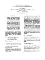
Figure 2-1. The melt spinning process
6
Figure 2-2. Model of structure development in polymers: (a)amorphous, (b)
crystallization nuclei, (c) crystal lamellar and (d) spherulite
10
Figure 2-3 Model of molecular structure developed in as-melt spun HDPE
fibers [7].
11
Figure 2-4. Molecular mechanism of plastic deformation of parallel lamellae
in a polymer crystal [19].
12
Figure 2-5. Typical stress-extension curve for as-melt spun iPP fibers.
14
Figure 2-6. True stress-draw ratio curves as a function off strain rate (E1: the
onset of crystallization, E2: the onset of regime 2 crystallization
[25].
14
Figure 2-7. Mechanism of translational slippage between groups of
crystallites [4].
15
Figure 2-8. Model illustrating reversible deformation of raw structure
exiting in highly oriented as-melt spun iPP fibers [26].
16
Figure 2-9. WAXD pattern of PLLA α-crystalline [34].
19
Figure 2-10. WAXD patterns of: (a) α-crystalline structure in as-melt spun
PLLA fibers, (b) β-crystalline structure in as-solution spun
PLLA fibers [36].
20
Figure 2-11. FESEM images of PS fibers electrospun from THF (35wt%
PS/THF) at different relative humidity: (a) 50% relative
humidity, (b) 30% relative humidity.
29
Figure 2-12. Beaded PEO fibers [47].
29
Figure 2-13. (a) Poly(ether imide) ribbons fibers, (b) a wrinkled bend [67].
30
Figure 2-14. SEM images of branched (a) HEMA fibers, (b) PS fibers and (c)
Poly(ester imide) [67].
30
Figure 2-15. A rotating hollow drum collector with a sharp pin [72].
31
Figure 2-16. A rotating wire drum collector [73].
32
Figure 2-17. A knife-edged bar-induced diagonally aligned fibers on the tube
(a) microphotograph at lower magnification, (b) SEM photo at
higher magnification [77].
32
Figure 3-1. Schematic drawing of electrospinning setup.
39
xiii
Figure 3-2. Disc collector developed for electrospinning of aligned fibers.
40
Figure 3-3. Polymer concentration effects on the diameter of the electrospun
PLLA fibers.
43
Figure 3-4. Molecular weight effects on the morphology of the electrospun
PLLA fibers.
45
Figure 3-5. Solution conductivity effects on the diameter of the electrospun
P(LLA-r-CL) fibers.
47
Figure 3-6. Solution temperature effects on the diameter of the electrospun
PLLA fibers.
49
Figure 3-7. Applied voltage effects on the diameter of the PLLA (Mw:
300K) fibers electrospun from solutions with different polymer
concentration.
51
Figure 3-8. Volume feed rate effects on the diameter of the PLLA (Mw:
300K) fibers electrospun from solutions with different polymer
concentration.
51
Figure 3-9. Electrospun fiber diameter as a function of take-up velocity.
53
Figure 3-10. SEM images of PLLA fibers electrospun at different humidity
level; (a) flat fibers electrospun at below humidity of 48%, (b)
uniform fibers electrospun between 48 and 85%.
54
Figure 3-11. Diameter of electrospun uniform PLLA fibers as a function of
humidity level.
54
Figure 3-12. Processing map obtained based on the systematic parameter
study: (a) jet drawability (affected by solvent properties, applied
voltage, take-up velocity), (b) mass of polymer (affected by
polymer concentration, applied voltage, volume feed rate)
58
Figure 3-13. The jet drawing-related parameters.
59
Figure 3-14. TEM image of ultra-fine PLLA fibers: (a) at lower
magnification, (b) at higher magnification.
61
Figure 3-15. Disc collectors developed for electrospinning of aligned fibers:
(a) conductive square-shaped table, (b) non-conductive tubular-
shaped table fixed on the edge of a disc collector.
62
Figure 3-16. Fiber orientation as a function of table materials: PCL fibers
electrospun on tables made from (a) conductive materials, (b)
non-conductive material.
62
xiv
Figure 3-17. Fiber orientation as a function of take-up velocity: PLLA fibers
electrospun at (a) 63m/min, (b) 630m/min.
63
Figure 3-18. SEM image of 3-D architecture with PCL aligned nanofibers
directed at 0
o
, -45
o
and +45
o
.
64
Figure 3-13. The jet drawing-related parameters.
69
Figure 3-14. TEM image of ultra-fine PLLA fibers: (a) at lower
magnification, (b) at higher magnification.
71
Figure 3-15. Disc collectors developed for electrospinning of aligned fibers:
(a) conductive square-shaped table, (b) non-conductive tubular-
shaped table fixed on the edge of a disc collector.
72
Figure 3-16. Fiber orientation as a function of table materials: PCL fibers
electrospun on tables made from (a) conductive materials, (b)
non-conductive material.
72
Figure 3-17. Fiber orientation as a function of take-up velocity: PLLA fibers
electrospun at (a) 63m/min, (b) 630m/min.
63
Figure 3-18. SEM image of 3-D architecture with PCL aligned nanofibers
directed at 0
o
, -45
o
and +45
o
.
64
Figure 4-1. Disc collector for single nanofibers.
74
Figure 4-2. Procedures to prepare single nanofiber sample: (a) short time
electrospinning, (b) pick aligned nanofibers onto a paper frame,
(c) removing non-required nanofibers and (d) single nanofiber
sample.
74
Figure 4-3. SEM images of electrospun P(LLA-b-CL) fibers.
76
Figure 4-4. (a) XRD diagram and (b) DSC thermogram of electrospun
P(LLA-b-CL) fibers.
76
Figure 4-5. Typical stress-strain curves of electrospun P(LLA-b-CL)
nanofiber membrane under tensile loading.
77
Figure 4-6. Fiber orientation angles in the P(LLA-b-CL) membranes during
the tensile deformation.
78
Figure 4-7. SEM micrograph of an electrospun P(LLA-b-CL) (75/25wt%)
membrane during the tensile deformation (at point C).
78
Figure 4-8. SEM images of PLLA fibers electrospun from solutions with
different polymer concentration of: (a) 7.5wt% and (b) 12.5wt%.
80
xv
Figure 4-9. Polymer concentration effects: (a) XRD diagram and (b) DSC
thermogram of PLLA fibers electrospun from 7.5wt% and
12.5wt% solutions.
81
Figure 4-10. SEM images of PLLA fibers electrospun from solutions
consisting of: (a) DCM/Pyridine (60/40wt%) and (b)
DCM/Methanol (80/20wt%).
83
Figure 4-11. Effects of solvents properties: (a) XRD diagram and (b) DSC
thermogram of PLLA fibers electrospun from 7.5wt% solutions
with DCM/Pyridine (60/40wt%) and DCM/Methanol
(80/20wt%).
85
Figure 4-12. SEM images of PLLA fibers electrospun from solutions at: (a)
room temperature, and (b) 40
o
C and (c) 70
o
C.
86
Figure 4-13. Solution temperature effects: (a) XRD diagram and (b) DSC
thermogram of PLLA fibers electrospun from solutions at room
temperature, and 40
o
C and 70
o
C.
87
Figure 4-14. SEM images of PLLA fibers electrospun at different take-up
velocity of: (a) 63m/min, (b) 630m/min, (c) 1,260m/min and (d)
1,890m/min.
89
Figure 4-15. Take-up velocity effects: (a) XRD diagram and (b) DSC
thermogram of PLLA fibers electrospun at 63m/min, 630m/min,
1,260m/min and 1,890m/min.
90
Figure 4-16. WAXD pattern of PLLA fibers electrospun at: (a) 63m/min, (b)
630m/min and (c) 1,890m/min.
91
Figure 4-17. Tensile stress-strain curves of PLLA single nanofibers
electrospun at take-up velocity of 63, 630 and 1,890m/min.
92
Figure 4-18. SEM micrographs of fractured PLLA single nanofibers after
tensile tests: (a) 63m/min and (b) 630m/min.
92
Figure 4-19. SEM images of PCL fibers electrospun from solutions consisting
of: (a) CHCl
3
/Pyridine (60/40wt%) and (b) CHCl
3
/Methanol
(80/20wt%).
95
Figure 4-20. Effects of solvents properties: (a) XRD diagram and (b) DSC
thermogram of PCL fibers electrospun from 10wt% solutions in
CHCl
3
/Pyridine (60/40wt%) and CHCl
3
/Methanol (80/20wt%).
96
Figure 4-21. SEM images of PCL fibers electrospun at: (a) 63m/min and (b)
630m/min.
98
xvi
Figure 4-22. Take-up velocity effects: (a) XRD diagram and (b) DSC
thermogram of PCL fibers electrospun at 63 and 630m/min.
99
Figure 4-23. SEM images of P(LLA-r-CL) fibers electrospun at: (a) 63m/min
and (b) 630m/min.
101
Figure 4-24. XRD diagram of electrospun P(LLA-r-CL) fibers at 63 and 630
m/min.
101
Figure 5-1. SEM images of as-spun, annealed fibers spun at 63, 630, 1,260
and 1,890m/min.
115
Figure 5-2. Annealing effects on PLLA fibers electrospun at different take-
up velocity: (a) XRD diagram and (b) DSC thermogram.
116
Figure 5-3. Tensile stress-strain curves of annealed PLLA single nanofibers
electrospun at 630 and 1,890m/min.
118
Figure 5-4. SEM images of as-spun, annealed and hot-drawn PLLA fiber
bundles.
119
Figure 5-5. Hot-drawing effects on PLLA nanofibers spun at 63m/min: (a)
XRD diagram and (b) DSC thermogram.
121
Figure 5-6. Tensile stress-strain curves of hot-drawn PLLA single
nanofibers electrospun at take-up velocity of 63m/min.
122
Figure 5-7. Hot-drawing effects on PLLA nanofibers spun at 630m/min: (a)
XRD diagram and (b) DSC thermogram.
124
Figure 5-8. Hot-drawing effects on annealed PLLA nanofibers spun at
630m/min: (a) XRD diagram and (b) DSC thermogram.
126
Figure 5-9. WAXD patterns of as-spun, annealed and hot-drawn PLLA fiber
bundles.
127
Figure 5-10. Structural model of electrospun PLLA nanofibers followed by
hot-drawing.
129
Figure 5-11. SEM images of as-spun, annealed and hot-drawn PLLA fiber
bundles with small scale diameter.
136
Figure 5-12. Hot-drawing effects on small scale PLLA nanofiber bundles
spun at 630m/min: (a) XRD diagram and (b) DSC thermogram.
136
Figure 5-13. WAXD patterns of as-spun, annealed and hot-drawn PLLA fiber
bundles with small scale diameter.
137
xvii
Publication lists
1) Wei He, Thomas Yong, Zu Wei Ma, Ryuji Inai, Wee Eong Teo, Seeram
Ramakrishna, “Biodegradable Polymer Nanofiber Mesh to Maintain Functions
of Endothelial Cells”, Tissue Engineering, accepted
2) S. Ramakrishana, T.C. Lim, R. Inai, K. Fujihara, “Modified Halpin-Tsai
Equation for Clay-Reinforced Polymer Nanofiber”, Mechanics of Advanced
Materials and Structures, 13 (2006) pp.77-81
3) R. Inai, M. Kotaki, S. Ramakrishna, “ Structure and Property of Electrospun
Single Nanofibers”, Nanotechnology, 16 (2005) pp.208-213, selected as featured
article and cover page of the journal
4) S-H, Tan, R. Inai, M. Kotaki, S. Ramakrishna, “Systematic Parameter Study for
Ultra-Fine Fiber Fabrication via Electrospinning Process”, Polymer, 46 (2005)
pp.6128-6134
5) R. Inai, M. Kotaki, S. Ramakrishna, “Deformation Behavior of Electrospun
P(LLA-CL) Nonwoven Membranes under Uniaxial Tensile Loading”, Journal of
Polymer Science: Polymer Physics, 43(22) (2005) pp. 3205-3212
6) C.Y. Xu, R. Inai, M. Kotaki, S. Ramakrishna, “Electrospun Nanofiber
Fabrication as Synthetic Extra Cellular Matrix and Its Potential for Vascular
Tissue Engineering”, Tissue Engineering, 10 (2004) pp. 1160-1168
xviii
7) C.Y. Xu, R. Inai, M. Kotaki, S. Ramakrishna, “Aligned Biodegradable
Nanofibrous Structure: A Potential Scaffold for Blood Vessel Engineering”,
Biomaterials, 25 (2004) pp.877-886
Chap.1
1
CHAPTER I
INTRODUCTION
In the 1950s and 60s, properties of polymers were found to be strongly related to
their molecular arrangement and chemical constitutes. Therefore, it became essential
to make clear how an assembly of macromolecules develops structures; how specific
molecular arrangement can be induced; and how these structures are related to
properties. Researches to study the processing-structure-property relationship (PSP
relathionship) of polymer fibers are particularly important since they show a
potential for their mechanical property. Such high mechanical properties are
obtained with their ordered molecular structure which is formed as a result of
drawing of the fibers during the spinning process. Recently, some processing have
attracted attention to produce polymer nanofibers since the polymer nanofibers are
good candidates in many application fields such as tissue engineering scaffolds,
filtration media, protective cloth, and so on. This has given rise to a great interest in
researches to study the PSP relationship in polymer nanofibers.
Objectives of This Research
The main aim of the research was to investigate processing-structure-property
Chap.1
2
relationship in electrospun polymer fibers. The objectives were addressed separately
in processing, structure and properties studies.
In the processing studies, the objectives were
1) To control electrospun fiber dimension by studying processing parameters
systematically. The dimension was observed under SEM and TEM.
2) To fabricate 2-D and 3-D architecture with electrospun aligned nanofibers by
developing a collector
The objective of the structure studies was
3) To investigate how a specific molecular arrangement or highly ordered structure
is formed into the electrospun polymer nanofibers. Molecular structures of the
electrospun nanofibers were characterized using XRD and DSC. The studies
particularly focused on the effects of the processing parameters (dominant
parameters found in processing-fiber dimension studies and take-up velocity)
and post-processing parameters (hot-drawing ratio) on the development of the
molecular structure.
In the properties studies, the objective was
4) To develop a method to collect electrospun single nanofibers, and make clear the
relationship between mechanical properties and the molecular structure
developed in the nanofibers. Tensile test of the single nanofibers was conducted
Chap.1
3
using a nano tensile testing system (Nano Bionix, MTS) with 500 mN load range,
and 50nN load resolution
The research was conducted mainly using poly(
L
-lactide acid) (PLLA) which has
potential tissue engineering applications as a suture in microsurgery, tissue
engineering scaffolds due to its good biocompatibility and biodegradability. The
polymer nanofibers can also be good candidates as reinforcement in composite
materials. In the electrospinning, there are a number of parameters and most of
which were investigated in the processing studies. The results of the processing
studies were used to identify some parameters that have an important role in the
development of the molecular structure in the electrospun nanofibers. Subsequently,
the structure studies focused on only these more important parameters. The results of
studies in the PSP relationship in the electrospun nanofibers should offer a way to
engineer polymer nanofibers to meet the specific demands such as dimension and
properties, of the nanofiber applications, and the results, hence, should contribute to
further expansion of the nanofiber applications. The results of the studies may also
contribute to a better understanding of how an assembly of molecules develops
structure if a scale of fiber diameter is in the nanometer range and how the molecular
structure affects mechanical properties. More details of the structure development
and the structure-properties relationship in micron scale of melt-spun / dry-spun
Chap.1
4
fibers will be described in chapter 2. The description would provide the useful
information to understand the significant finding in the thesis, that is, the
development of the molecular structure and its effects on the mechanical properties
in the polymer nanofibers,
Chap.2
5
CHAPTER II
LITERATURE REVIEW
2-1. Overview of Polymer Micronfibers Processing
In the polymer fibers based industries, a micro scale of polymer fibers
(micronfibers) produced by either melt-spinning or solution-spinning have been
widely used. Past research works based on these micronfibers have gave us the idea
that how to control molecular structure by processing; and how the molecular
structure affects mechanical properties of the fibers. Literature review of the above
works would provide fundamental knowledge to investigate
processing-structure-properties relationship in electrospun nanofibers.
2-1-1. Melt-spinning Process
The idea of the melt spinning process was given by R. A. Brooman in 1845 [1]. The
melt spinning process involves melting and extrusion of the material to be processed
through a multi-hole capillary die (called a spinneret), followed by cooling and
solidification to form filaments. The produced filaments can be wound on a bobbin.
In this process, tensile force is usually applied to draw the filaments and results in a
decrease in a fiber diameter.
Chap.2
6
A standard setup of melt-spinning is
illustrated in Figure 2-1. Pellets formed
polymer is fed into an extruder where it
is melt and delivered to metering pump
and ejected from spin pack with a
multifilament spinneret. The extruded
filaments are drawn down to smaller
diameter, while they are simultaneously cooled / quenched by air blowing across the
filament bundle. The resulting filaments are either wound onto a bobbin or they are
passed directly to another processing step such as drawing or texturing.
The major parameters for melt-spinning are as follows,
Processing parameters
- extrusion temperature
- mass flow rate of polymer through each spinneret hole
- take-up velocity of the wound-up or deposited filaments
- the spinline cooling conditions
- spinneret orifice shape, dimensions and spacing
- the length of spinline
Figure 2-1. The melt spinning process.
Polymer Pellets
Hopper
Extruder
Metering Pump
Spin Pack
Quench Air
Spinning Filaments
Lube Applicator
Godet Rolls
To Winder
Polymer Pellets
Hopper
Extruder
Metering Pump
Spin Pack
Quench Air
Spinning Filaments
Lube Applicator
Godet Rolls
To Winder