Carbon rich silicon (si1 ycy)for defect engineering of ion implantation damage in devices activated by solid phase epitaxy
Bạn đang xem bản rút gọn của tài liệu. Xem và tải ngay bản đầy đủ của tài liệu tại đây (2.32 MB, 170 trang )
CARBON RICH SILICON, Si
1-y
C
y
, FOR DEFECT
ENGINEERING OF ION IMPLANTATION DAMAGE
IN
DEVICES ACTIVATED BY SOLID PHASE EPITAXY
TAN CHUNG FOONG
(B.Eng (Hons) NUS)
A THESIS SUBMITTED FOR THE DEGREE OF
DOCTOR OF PHILOSOPHY
DEPARTMENT OF ELECTRICAL AND COMPUTER ENGINEERING
NATIONAL UNIVERSITY OF SINGAPORE
2006
1
“… Every day you may make progress. Every step may be fruitful. Yet there will stretch
out before you an ever-lengthening, ever-ascending, ever-improving path. You know you
will never get to the end of the journey. But this, so far from discouraging, only adds to
the joy and glory of the climb. “
Sir Winston Churchill, British Prime Minister (1874 - 1965)
i
Acknowledgements
However seemingly modest these acknowledgements are compared to my
gratitude, I sincerely hope, nevertheless, that the following recognitions are appreciated.
Developing a fundamental understanding is a necessarily lonely adventure which
requires tremendous patience. For the times when the dreadful “blockades” step in with
unpredictable anomalies, I wish to express the enjoyable insights and exchange of
perspectives between the unofficial mentors from Chartered Semiconductor. I am
especially grateful to Dr. Lee Hyeok Jae whose detailed observations have taught me how
to look at results more carefully, and the aggressive optimism of Dr. Liu Jinping whose
enthusiasm continues to propel endlessly. To the Special Project students, I am grateful
for their making of a wonderful research atmosphere to work in. The frequent teases,
meals and occasional outing had definitely lifted a huge burden off discussion about the
rocking curves with Lydia. Oh what fun, it has been!
I am most genuinely grateful to my research supervisor Assoc. Prof. Chor Eng
Fong, from whom I have learned the most of all. Her patience, boundless insights, and
unique talent to communicate have been a remarkable learning experience. I consider
myself blessed to have had the opportunity to work with such combination of excellence
both as a navigator and a teacher.
Special thanks also goes to Dr. Lap Chan for enrolling me in the Chartered-URI
program, the training and support which he provided. The technical presentations every
Wednesday have broadened my horizons tremendously. To Kheng Chok, thank you for
the guidance through the manufacturing protocol and integration perspective of the
fabrication process.
ii
At the university, colleagues from the Centre of Optoelectronics (COE), Haiting,
Lip Khoon and Janis, who have selflessly lent a helping hand in training for operating the
rapid thermal anneal and e-beam evaporator equipment. Many apologies for the
“troubleshooting” phone calls on Sundays and weekends too!
A special mention also goes to my family and friends, who knowingly or not, gave
me the most appreciative support.
Finally, I humbly thank God, for His presence and blessings, which has made this
experience a safe and truly enriching journey.
Thank you all!
iii
Table of Contents
I. ACKNOWLEDGEMENTS i
II. TABLE OF CONTENTS iii
III. LIST OF TABLES x
IV. CHAPTER 1
INTRODUCTION AND MOTIVATION 1
1.1 Background 1
1.2 Technology Scaling 2
1.3 The challenging metal oxide semiconductor field effect transistor (MOSFET) 5
1.4 Significance of ion implantation 7
1.4.1 Implantation induced damage and annealing 9
1.4.2 Future Annealing Technologies 9
1.5 Research Objectives 13
1.6 Outline of the thesis 14
V. CHAPTER 2
LITERATURE REVIEW 16
2.1 Introduction 16
2.2 Solid phase epitaxial regrowth (SPER) annealing 16
2.2.1 Concept of SPER 17
2.2.1 Factors affecting SPER rate 18
2.3 Extended defect evolution and dissolution during annealing 21
2.4 Carbon in silicon 24
2.4.1 Carbon as a sink for silicon interstitial 24
2.4.2 Carbon and the suppression of boron diffusion 26
2.4.3 Enhanced boron diffusion 26
2.4.4 Suppressed boron diffusion in the presence of carbon 28
2.4.5 Secondary EOR suppression 30
2.4.6 Electrical activity in the presence of carbon 31
2.5 Devices with incorporated carbon 32
2.5.1 Heterojunction bipolar transistor (HBT) 33
2.5.2 Metal oxide semiconductor field enhanced transistor (MOSFET) 35
2.5.3 Strained silicon MOSFET 37
iv
VI. CHAPTER 3
GROWTH AND CHARACTERIZATION OF CARBON IN SILICON 38
3.1 Carbon in silicon 38
3.1.1 Epitaxy Incorporation of carbon 39
3.1.2 Maximizing substitutional carbon incorporation 40
3.2 Quantification of the carbon content 41
3.2.1 Quantification of substitutional carbon with HRXRD rocking curve 42
3.2.2 Deviation from Vegard’s law at low carbon concentration 44
3.2.3 HRXRD rocking curve to determine the composition of the epitaxial layer 45
3.2.4 Simulation of HRXRD rocking curve for the determination of the thickness and
composition of epitaxial layers 47
3.3 Determining the flow rate of methylsilane for the incorporation of carbon 49
VII. CHAPTER 4
CARBON AND SUPPRESSION OF SECONDARY IMPLANTATION DEFECTS
55
4.1 Introduction 54
4.2 Indium as EOR markers 55
4.3 Determining indium dose for EOR defect formation 56
4.3.1 Results and discussion 56
4.4 Indium segregation with different annealing temperature 58
4.4.1 Experimental Setup 59
4.4.2 Results and Discussions 60
4.5 Eliminating indium EOR defect using substitutional carbon 62
4.5.1 Background 62
4.5.2 Effects of substitutional carbon incorporation on implanted indium end-of-range
(EOR) defect under high temperature spike annealing conditions 64
4.5.3 Defect Suppression of Indium End-of-Range during Solid Phase Epitaxy
Annealing Using Si
1-y
C
y
in Silicon 69
4.6 Conclusions 72
VIII. CHAPTER 5
JUNCTION WITH CARBON INCORPORATION 74
5.1 Introduction 74
5.2 Gated Diode 75
5.2.1 Junction leakage dependence on gate biasing 75
5.2.3 Gate induced drain lowering (GIDL) 76
5.3 Incorporating carbon layer for device fabrication 78
5.3.1 S/D Implant Damage profile 79
5.3.2 Incorporating epitaxial layers to the substrate 80
5.3.3 Device fabrication 81
v
5.4 Junction leakage in carbon incorporated devices under SPER annealing 82
5.4.1 Results and discussion 83
5.4.2 Conclusion 86
5.5 Improving junction leakages in Si
1-y
C
y
devices 87
5.5.1 Thermal driving to reduce interstitial carbon concentration 87
5.5.2 Thermal driving and junction leakage suppression in Si
1-y
C
y
devices 90
5.6 Summary 95
IX. CHAPTER 6
FABRICATION AND CHARACTERIZATION OF CARBON INCORPORATED
NMOSFETS 96
6.1 Introduction 96
6.2 Device fabrication 99
6.2.1 Determination of the dimension of the carbon layer 98
6.2.2 Device Fabrication 102
6.3 Junction leakage of n
+
-p junctions of the nMOSFET 103
6.4 Gate stack characteristics 108
6.5 I-V characteristics of carbon incorporated n-MOSFET 112
6.6 Analysis of body effect 117
6.7 Reducing SPER annealing temperature 122
6.8 Summary 125
X. CHAPTER 7
SUMMARY AND FUTURE WORK 127
7.1 Summary 127
7.2 Future work 129
XI. APPENDICES
A.1 Effects of impurity on the SPER growth rate 130
A.2 Material data of selected group-IV elements 135
A.3 Fabrication of gated diode 136
A.4 Fabrication of the nMOSFET 138
A.5 Channel dopant extraction with capacitance measurements [105] 141
A.6 Transistor with 1 masking step 143
vi
XII. APPENDIX B
List of publications and presentations resulting from this work 146
XIII. LIST OF REFERENCES 148
vii
List of Figures
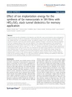
Figure 1.1 Actual and forecast sales figures in the world semiconductor industry [1].1
Figure 1.2 Evolution of number of transistors packed into each of Intel’s new
generation of microprocessors, describing Moore’s law [2] 3
Figure 1.3 Cost of fabrication of transistors, DRAM and FPGA decreases
progressively over the years with the advancement of semiconductors
devices 4
Figure 1.4 Actual US government spending on computers compared to that as if the
computer cost were maintained at a pricing at 1995 [3] 4
Figure 1.5 Increasing processing power over the years which increases with the
number of transistors packed in to the microprocessor [4] 5
Figure 1.6 Cross-sectional XTEM image illustrating (a) the interconnection involving
contacts, vias and 6 levels of metal lines. Inset: Circle compares the
relative dimension between the MOSFET with the contacts and vias. (b) a
180 nm gate length MOSFET Courtesy: Chartered Semiconductor Ltd 6
Figure 1.7 Micrograph of biological structures illustrating the dimension of (a) strand
of hair and (b) an influenza viral strain (Source: www.about.com). It can
be seen that an influenza virus is approximately 1000 times smaller than a
strand of hair 6
Figure 1.8 Illustration of the various implant regions in CMOS architecture. Source:
Axcellis Technical Seminar 8
Figure 2.1 Different damage regions in crystal caused by an amorphizing
implantation 18
Figure 2.2 Solid-phase epitaxial regrowth versus annealing time for an amorphous
implanted layer on silicon 19
Figure 2.3 (a) Regrowth rate versus the orientation of Si substrate for implanted
amorphous Si annealed at 550 °C. (b) Arrhenius plot for isochronal anneal
of amorphous layers on Si substrate for different substrate orientation [29]
20
Figure 2.4 Evolution of damage in implanted region during an annealing process 22
Figure 2.5 (a) Density of extended defects in the EOR, and (b) Density of interstitials
bound by extended defects in the EOR as a function of annealing time at
750 °C. [14] 23
viii
Figure 2.6 Schematics illustrating (a) an interstitial silicon located near a
substitutional carbon species in a silicon lattice. (b) The resulting highly
mobile interstitial carbon complex formed by binding the interstitial to the
carbon atom 25
Figure 2.7 Schematics illustrating (a) an interstitial silicon located near a
substitutional carbon species in a silicon lattice. (b) The resulting highly
mobile interstitial carbon (C
i
) species formed 25
Figure 2.8 Schematics illustrating (a) an interstitial silicon located near a
substitutional boron in a silicon lattice. (b) the resulting highly mobile
boron interstitial cluster formed 27
Figure 2.9 The profiles of boron after diffusion (a) without carbon, (b) with carbon in
the substrate. (c) Uniform carbon profile achieved by multiple
implantations into the silicon substrate [19] 29
Figure 2.10 Boron diffusion profiles for a superlattice containing a buried spike of
substitutional carbon [19] 30
Figure 2.11 SIMS profiles of (a)Si
0.8
Ge
0.2
, (b)Si
0.795
Ge
0.2
C
0.05
, and (c)Si
0.795
Ge
0.2
C
0.005
following ion implantation and annealing at 755 °C [25] 33
Figure 2.12 Gummel plots and collector current versus base-collector voltage plots for
HBTs with a Si n-emitter and (a) a SiGe base, and (b) a SiGeC base [25].
34
Figure 2.13 Threshold voltage as a function of gate-length for the Si
1-y
C
y
devices and the
control pure silicon device [58] 36
Figure 2.14 (a) The profiles of boron halo in Si and SiGe:C layer, (b) I
D
-V
gs
sweep
comparing the short channel effects of the SiGe:C device and the silicon
control device [60] 36
Figure 3.1 Substitutional carbon content (measured by XRD) versus total carbon
content (measured by SIMS) for Si
1-y
C
y
films grown by Chemical Vapor
Deposition at different temperatures and SiH
4
partial pressures [69] 41
Figure 3.2 Schematics illustrating (a) the lattice arrangement of a silicon substrate,
and (b) a pseudomorphically strained Si
1-y
C
y
layer grown on top of a
silicon substrate.
y
Si
a represents the lattice constant of silicon and symbols
⊥
− yy
CSi
a
1
and
||
1 yy
CSi
a
−
indicate the lattice constant of the carbon layer in the
indicated direction 43
Figure 3.3 Lattice constant of silicon, relaxed Si
1-y
C
y
and strained Si
1-y
C
y
as a function
of carbon fraction. Inset indicates the value of lattice parameters of single
crystal silicon and carbon 43
ix
Figure 3.4 Dependence of the perpendicular lattice constant
⊥
− yy
CSi
a
1
of a
pseudomorphic Si
1-y
C
y
epilayer for y < 0.12 %. Dashed lines: calculated
lattice parameters according to Vegard’s rule between Si and C; dash-
dotted lines: calculations using Vegard’s rule between Si and β-SiC; solid
lines: theoretical data according to equation (3.7). Solid symbols indicate
the experimental data points. [72] 44
Figure 3.5 A ω-2θ rocking curve measurement of a pseudomorphically strained
carbon epitaxial layer. Inset: Structure of the grown epitaxial layer 45
Figure 3.6 The angular distance between the epitaxial layer peak and the substrate
peak increases with higher carbon content. Inset: Structure and the
physical thickness of the epitaxial substrate layer 46
Figure 3.7 Fitting of a rocking curve simulation performed to model an actual structure
with two epitaxial layers. Inset shows the structure with a silicon cap layer
grown on top of a pseudomorphic carbon layer 48
Figure 3.8 Structure of the epitaxial layer used in determining the flow rate of
methylsilane 49
Figure 3.9 ω-2θ HRXRD rocking curve scans performed on the grown Si
1-y
C
y
epitaxial layers with different methylsilane flow rates 50
Figure 3.10 Rocking curve simulations performed on samples with two epitaxial layers,
Si
1-y
C
y
followed by a silicon cap layer, as shown in the inset in (a). The Si
1-
y
C
y
is grown with methylsilane flow rates of (a) 10, (b) 50, (c) 75 and (d)
100 sccm 51
Figure 3.11 Carbon content in the layers with different methylsilane flow rates 52
Figure 3.12 Thicknesses of the carbon layer, capping layer and the total epilayer
grown at the different methylsilane flow rates 52
Figure 4.1 Indium profile after implantation, at doses ranging from 4 × 10
13
to 5 ×
10
14
cm
-2
, and spike annealing at 1050 ˚C. The segregation of indium into
two peaks are observed at a dose of 7 × 10
13
cm
-2
and above, suggesting the
formation of EOR at these implant doses 57
Figure 4.2 XTEM Image showing the presence of dislocation loops at indium implant
dose of 1×10
14
cm
-2
at a depth of ~70 nm 58
Figure 4.3 SIMS measurements indicating the profiles in silicon of implanted indium
at 115 keV and 1×10
14
cm
-2
after annealing in nitrogen ambient for 2
minutes at 650, 750 and 800 ˚C 60
Figure 4.4 SIMS measurements of indium profile (implant dose of 1×10
14
cm
-2
at 115
keV) after different annealing conditions. Segregation of indium into
dislocation loops is observed at 650 ˚C 62
x
Figure 4.5 Schematics showing (a) Damage profile resulting from an amorphizing
implantation, and (b) the intended relative position of substitutional carbon
layer, Si
1-y
C
y
, to be grown with respect to the implant profile 63
Figure 4.6 Simulation fit of the measured
θ
ω
2
−
HRXRD rocking curve scan 65
Figure 4.7 XRD rocking curve measurements comparing the samples with
substitutional carbon after different processing steps of implantation and
anneal 66
Figure 4.8 SIMS profile of indium comparing the as-implanted sample and upon
spike anneal for sample with and without ~0.1% substitutional carbon. C
sub
indicates the location of the Si
1-y
C
y
epitaxial layer 66
Figure 4.9 XTEM images for samples (a) without and (b) with substitutional carbon
after high temperature anneal. (b) clearly shows that dislocation loops are
absent 67
Figure 4.10 XTEM image revealing the EOR defect band in the 650 ˚C annealed
control silicon sample 70
Figure 4.11 SIMS measurements indicating the suppressed indium profiles of
implanted indium after annealing in nitrogen ambient for 2 minutes at 650,
750 and 800 ˚C for samples with the carbon layer present 71
Figure 4.12 XTEM image revealing the absence of the EOR defect band in 650 ˚C
annealed sample with carbon layer in the silicon substrate 71
Figure 5. 1 Schematic illustrating the top view and cross-sectional view of a gated
diode 75
Figure 5.2 Junction leakage behavior of the gated diode at different gate biases 76
Figure 5.3 The depletion region of the channel-junction under an (a) forward biased
junction and gate voltage at flatband, (b) reverse biased junction and gate
voltage at flatband, (c) reverse biased junction and gate voltage at
accumulation (d) reverse biased junction and gate voltage at strong
accumulation 78
Figure 5.4 (a) Cross sectional view of a gated diode. Solid dots represent the damage
in EOR region of the implantation. (b) Flowchart showing the fabrication
procedure of the devices. Shaded boxes represent the main difference in
this work compared to a normal device fabrication 79
Figure 5.5 UT-Marlowe simulation of the S/D implant illustrating the arsenic profile
and its associated damage indicated by the amorphous and end-of-range
(EOR) regions 80
Figure 5.6 Flowchart illustrating the fabrication flow and split conditions (W01, W02,
W03 and W04) of the devices under either SPER or RTA activation. W01
xi
and W02 are Si
1-y
C
y
devices (shaded), and W03 and W04 are pure silicon
devices 82
Figure 5.7 Junction leakage characteristics showing the leakage profile of the various
diodes fabricated. The change in the slope of the leakage profile at a bias
larger than 2V is due to the onset of GIDL current 83
Figure 5.8 XTEM images of the 700 ˚C, 30 s annealed diodes reveal: (a) an EOR
defect band remaining after fabrication in pure silicon (W03), and (b) an
EOR defect band absent after fabrication in silicon with a Si
1-y
C
y
layer
(W01) 84
Figure 5.9 Similar junction leakage temperature dependence of the diodes with a Si
1-
y
C
y
layer (W01 and W02) to that of the control diode annealed at a high
temperature of 950 ˚C for 30 s (W04) suggests that these diodes have
identical mode of leakage current 85
Figure 5.10 Arrhenius plots of the diffusivities of silicon interstitial (I), substitutional
carbon (C
s
) and interstitial carbon (C
i
) in silicon as a function of annealing
temperature 89
Figure 5.11 Diffusion lengths for C
i
and C
s
for various annealing times at 850 °C 89
Figure 5.12 Annealing time dependence of the junction behavior of gated diode
comparing (a) silicon device, and (b) Si
1-y
C
y
device at an 850ºC annealing
temperature. The horizontal lines in the figures indicate the off current
requirements of low standby power (LSTP) devices at the proposed supply
voltage for the 45 nm and 32 nm technology nodes according to the
ITRS[9] 92
Figure 5.13 Junction leakage (at a reverse bias of 1 V) as a function of annealing time
of (a) Si and Si:C devices, and (b) comparison with closest referenced
devices annealed under a spike annealing of 1050 ºC and flash annealing at
1300 ºC [86] 93
Figure 5.14 Arrhenius plot of the devices fabricated at different SPER annealing
temperature ranging from 550 to 850 °C 95
Figure 6.1 (a) Schematic illustrating the position of the Si
1-y
C
y
layer relative to the
implantations in MOSFET. Textured region represents the buried Si
1-y
C
y
layer. Punchthrough and threshold implants are indicated by dashed and
dotted lines, respectively. The EOR defects are represented by solid dots.
(b) Schematic illustrating the layout dimensions of the source/drain (S/D)
region. (c) Flowchart showing the device fabrication sequence. Shaded
steps highlight the major differences compared to a conventional
nMOSFET fabrication 97
Figure 6.2 Simulated as-implant profile in the (a) S/D junction regions, and (b)
channel region of the MOSFET. Defect profile in the S/D junction regions
xii
is represented by the dashed line in (a). Amorphization and EOR defects
are minimal in the channel region 99
Figure 6.3 (a) Schematic showing the locations of the channel implant profiles and
EOR defect regions in the S/D junction regions with respect to the carbon
(Si
1-y
C
y
) layer. (b) Table summarizing the dimensions of the epitaxial
layers and the overlap between the Si
1-y
C
y
layer, and the implant profiles
and defect regions 101
Figure 6.4 Cumulative distribution of junction leakages measured on transistors at V
d
= 1.0 V. The junction is located within a region of punchthrough and
channel implant 104
Figure 6.5 Schematic indicating the possible additional junction leakage tunneling
path with the presence of trap charges at the Si-SiO
2
interface 106
Figure 6.6 Junction leakage versus reverse bias. GIDL current manifests at large
reverse bias. Dashed lines indicate the off leakage current at the given
operating voltage by the ITRS [9] 106
Figure 6.7 Schematics illustrating components contributing to a junction leakage
current in a transistor. SCE is assumed to be eliminated. Arrows indicate
the regions of the current component 107
Figure 6.8 (a) Cumulative distribution of the gate leakage current and (b) gate leakage
behavior of the fabricated devices 109
Figure 6.9 C-V measurement performed on capacitors with an area of 65.6 × 130 μm
2
at a frequency of 100 kHz 110
Figure 6.10 Equivalent oxide thickness (EOT) versus the physical thickness measured by
secondary ion mass spectroscopy (SIMS). Numbers indicate the thickness
of the t
cap
layers. Inset: SIMS profiles of the gate oxide. Horizontal line
indicates the reference used for extraction of the oxide thickness 111
Figure 6.11 (a) I
D
-V
gs
characteristics comparing the devices fabricated with t
cap
= 60
nm or 180 nm (control). (b) The I
D
-V
ds
measurements showing an
improvement in the current drive for the Si
1-y
C
y
device (t
cap
= 60 nm)
compared to the control 112
Figure 6.12 (a) Depth dependence of the drive current, I
D,sat
measured on devices with
a t
cap
= 20, 60 90 and 180 nm (b) Normalized drive current, I
D,sat
with its
associated I
off
are shown for the various devices 114
Figure 6.13 (a) The capacitance-voltage (C-V) profiling of the acceptor concentrations
for devices with a silicon cap layer thickness of 20, 60, 90 and 180 nm. (b)
Effect of the channel concentration to the enhancement factor in the
measured drive current. Numbers represent the thicknesses of the carbon
layers 116
Figure 6.14 (a) Effect of body bias on the change in threshold voltage, ΔV
th
, of n-
MOSFETs with rapid thermal annealing at 850 ˚C (solid symbols) or 950
xiii
˚C (empty symbols) for 30 s. (b) The extracted body sensitivity parameter,
γ, versus increasing silicon cap thickness (t
cap
) 118
Figure 6.15 Acceptor concentration of devices in the channel with a silicon cap layer at
the thicknesses of 20, 60, 90 and 180 nm 120
Figure 6.16 (a) Effect of an increase in RTA temperature to 950 °C on the body
sensitivity parameter, γ, and effective concentration, N
eff
, for an n-
MOSFET with a Si
1-y
C
y
layer of t
cap
= 20 nm. (b) The combined body
sensitivity parameter, γ, for all fabricated devices versus increasing
eff
N .
The solid line represents the theoretical γ for a long channel device, γ
long
for comparison 121
Figure 6.17 (a) I
D
-V
gs
characteristics and (b) The I
D
-V
ds
, for a t
cap
= 20nm device
activated under SPER annealing of 750 °C for 10 mins 123
Figure 6.18 (a) I
D
-V
gs
characteristics and (b) The I
D
-V
ds
, for a t
cap
=20nm device
activated under SPER annealing of 550°C for 10 minutes 124
Figure 6.19 (a) I
d,sat
(V
gs
-V
th
=1.6V V
ds
= 2.0) and I
off
(minimum of I
D
-V
gs
sweep)
behavior of the Si
1-y
C
y
devices annealed at various SPER temperature 125
Figure A.1 Version 1 of (a) single mask transistor illustrating the drain, source and
gate region, and (b) the physical dimensions of the transistor. ……… 143
Figure A.2 (a) Schematics illustrating the dimensions of the layout of the transistor
and (b) the layout drawn in Cadence software 144
xiv
List of Tables
Table 1.1 Category, name of purpose of the implantations performed in CMOS
device fabrication 8
Table 3. 1 Extracted parameters of the epitaxial layers from the fitting of the rocking
curve simulation. The sample has two epitaxial layers where Si
1-y
C
y
is first
deposited followed by a silicon cap layer 48
Table 4.1 The annealing temperature and time for the various samples 59
Table 5.1 Pre-exponential factor (D
o
) and activation energy (E) for the diffusivities
of silicon interstitial (D
I
), substitutional carbon (
Cs
D
) and interstitial
carbon (
i
C
D
) in silicon [41] 88
Table A. 1 The effects of phosphorus incorporation to the SPER regrowth rate 131
Table A. 2 The effects of arsenic incorporation to the SPER regrowth rate 132
Table A. 3 The effects of boron incorporation to the SPER regrowth rate 133
1
CHAPTER 1
Introduction and motivation
1.1 Background
The world semiconductor market has been experiencing a long continued growth
in sales since its infancy, rising above heavy industries such as automobiles and steel. In
year 2004, the revenue according to the Semiconductor Industry Association (SIA) [1]
was US$ 220 Billion. Growth potential of the industry remains high and is forecast to
expand beyond US$ 300 Billion by year 2008, as shown in Fig. 1.1. The growth in
revenue in developed markets, such as Europe, the United States and Japan remains high,
indicating tremendous opportunities in the industry.
1980198519901995200020052010
0
50
100
150
200
250
300
350
World Semiconductor Sales
Forecast
Regional sales
US
Europe
Japan
Asia Pac
US Dollar ('Billion)
Year
Figure 1.1 Actual and forecast sales figures in the world semiconductor industry [1]
The motivation behind the phenomenal success and development of solid state
devices lies in their function as core components in electronics used in fields such as
computing, communication and information storage. As these solid state devices form the
2
fundamental building blocks of any electronic system, their demand rises in tandem with
the demand for electronics. It is remarkable that these devices find a place in the entire
spectrum of electronics which ranges from high performance devices required in
microprocessors units such as Intel’s Pentium
TM
, and Nvidia’s 3D-Graphics
TM
, to
computing less complex logic found in Field Programmable Gate Array (FPGA) used in
refrigerators and washing machines. Recent advancement in automobile technology has
the power converters made of the silicon chip to drive the hybrid engine, such as the one
used in Toyota’s Prius
TM
hybrid car.
Collectively, semiconductor devices may be classified into 3 segments:
i. Ultra large scale integration (ULSI) of complementary metal oxide semiconductor
(CMOS) - logic devices, dynamic random access memory (DRAM), static random
access memory (SRAM), electrically programmable read only memory (EPROM) ,
and read only memory (ROM)
ii. Discrete devices - power bipolar transistors, silicon control rectifiers, diodes,
operational amplifiers and optoelectronic devices.
iii. Dedicated integrated circuits (ICs) - microware devices, light emitting diodes (LED),
solid state lasers, photodetectors, and solar cells.
ULSI CMOS significantly dominates the market segments and its dominance is
projected to further increase with higher levels of integration in ULSI fabrication.
1.2 Technology Scaling
Technology advances in the fabrication of semiconductors have made dramatic
improvement over the years as devices today have been scaled to the nanometer regime.
3
Miniaturization of devices has allowed several billions of transistors to be placed into a
single chip. A trend first observed by Gordon E. Moore is that the transistor physical
feature size scales by a factor of two every year and this has been known widely today as
Moore’s Law [2]. Although observed nearly 40 years ago, Moore’s law remains valid
today. The number of transistors packed into each generation of Intel’s microprocessors
clearly follows the trend, as shown in Fig. 1.2. By the end of year 2005, the number of
transistors packed into a single microprocessor chip has exceeded 1 Billion!
Figure 1.2 Evolution of number of transistors packed into each of Intel’s
new generation of microprocessors, describing Moore’s law [2]
“Shrink to become cheaper”
A lucrative aspect which is inherent with the scaling is the economy of scale of
semiconductor device fabrication. By shrinking, manufacturers are able to squeeze more
devices per unit area, thus resulting in a higher packing density. This approach favorably
results in a reduced production cost of the single device which can be seen in Fig. 1.3 [1]
Cost of the ICs (i.e., DRAM, FPGA and microprocessors) per million units decreases
exponentially each year, consistent with the prediction of Moore’s Law. Eventually, the
4
reduced cost of production benefits consumers as sophisticated electronics are made more
affordable and readily available. One of such cost saving derived from scaling is
illustrated in Fig. 1.4, where the curves compare the actual spending by the US
government on computers to a pricing as if it was maintained at 1995 [3]. Cost reduction
derived from technology development offers a huge economic potential and this may
largely be attributed to the dramatic development of the semiconductor technology which
is achieved mainly through the scaling of these devices.
Transistors
FPGA
DRAM
Transistors
FPGA
DRAM
Transistors
FPGA
DRAM
Cost per million (US$)
Transistors
FPGA
DRAM
Transistors
FPGA
DRAM
Transistors
FPGA
DRAM
Cost per million (US$)
Figure 1.3 Cost of fabrication of transistors, DRAM and FPGA decreases
progressively over the years with the advancement of semiconductors
devices.[1]
1994 1996 1998 2000 2002 2004
0
20
40
60
80
100
120
140
160
Actual Spending
@ '95 Prices
US Dollar ('Billion)
Year
Source: Bureau of Economic Affairs
(www.bea.gov/bea/dn/comp-gdp.xls)
Figure 1.4 Actual US government spending on computers compared to
that as if the computer cost were maintained at a pricing at 1995 [3].
5
“Shrink to grow bigger”
Underlying the economic motivation, scaling of semiconductor devices bears deep
engineering significance. By shrinking, the smaller dimension devices offer better
performances. For example, a smaller transistor, in terms of the gate length, delivers
higher drive current which then permits faster switching speed in the individual transistor.
When packed into the microprocessor, the increasing transistor count unleashes higher
processing power which is shown in Fig. 1.5. The scaling of the single device may
potentially be amplified by 1 billion times! A similar explanation may be provided for
the increasing storage capacity in DRAM and non-volatile memory electronics, which
persists along with the scaling of the devices. Hence, the paradox, “shrink to become
larger.”
Figure 1.5 Increasing processing power over the years which
increases with the number of transistors packed in to the
microprocessor [4]
1.3 The challenging metal oxide semiconductor field effect
transistor (MOSFET)
Fig. 1.6(a) shows the level of complexity involved in a modern VLSI fabrication
process. Numerous layers of metal interconnection have to be deposited after the
6
completion of the MOSFET in order to electrically connect the devices. With today’s
manufacturing technology in microchip fabrication, the transistor size has already reached
50 nm, a dimension which is about half that of the influenza virus or about 2000 times
smaller than a strain of human hair. For a sense of the physical size of the transistor, Fig.
1.7 shows a micrograph image of a strand of hair (Fig. 1.7(a)) and an influenza viral
strain (Fig. 1.7(b)). Of all the structures involved in device fabrication, the size of the
MOSFET (inset in Fig. 1.6(b)) remains remarkably smaller.
Gate length = 180 nmGate length = 180 nm
(a) (b)
Figure 1.6 Cross-sectional XTEM image illustrating (a) the interconnection
involving contacts, vias and 6 levels of metal lines. Inset: Circle compares the
relative dimension between the MOSFET with the contacts and vias. (b) a 180 nm
gate length MOSFET Courtesy: Chartered Semiconductor Ltd.
(a) (b)
Figure 1.7 Micrograph of biological structures illustrating the dimension of (a)
strand of hair and (b) an influenza viral strain (Source: www.about.com). It can be
7
seen that an influenza virus is approximately 1000 times smaller than a strand of
hair.
As transistors continue to scale with the prediction of Moore’s Law, accuracy and
control of the processing steps during device fabrication becomes extremely sensitive and
critical to the slightest process variation. This makes the science and engineering of
CMOS an enormous challenge, yet equally intriguing.
1.4 Significance of ion implantation
In order to achieve a properly functioning MOSFET, selective regions of the
transistor, such as the channel, source and drain, must be precisely doped. Doping enables
electrical conduction in an otherwise electrically insulating semiconductor. Group V
elements of the periodic table such as phosphorus and arsenic are incorporated into
silicon (Group IV) for n-type semiconductor and Group III elements such as boron and
indium for p-type semiconductor. Dopant incorporation may be achieved mainly through
a diffusion process or ion implantation.
Ion implantation remains the industrial standard to introduce dopants into the
silicon substrate for the fabrication of devices. This is because it is the best known
method for introducing high dopant concentration above classical solid source diffusion
with good precision and accuracy. In order to appreciate the significance of the
implantation process, it is necessary to examine the CMOS device architecture. Fig. 1.8
shows the regions of the CMOS which are selectively doped in order to achieve a
properly functioning CMOS device. All these regions are realized using implantation in
today’s semiconductor manufacturing facilities. Each region has a purpose, which is
essentially to tailor the electric field distribution within the device. Some of the purpose
of these implanted regions and its naming convention are summarized in Table 1.1.
8
Figure 1.8 Illustration of the various implant regions in CMOS
architecture. Source: Axcellis Technical Seminar
Category Implant Name Purpose
i. Well Background doping for isolation
ii. Field Isolation between the field oxide
iii. Punchthrough
Prevent punchthrough between the source
and drain (S/D)
Channel / Well Doping
iv. Threshold (V
T
) Adjusting the threshold voltage
Poly doping Poly pre-doped
Heavily doped the polysilicon gate for high
conductivity
Halo / Pocket Implant to prevent S/D shorting
S/D Extension
For short channel effects and hot carrier
degradation
Extension and S/D
doping
S/D
Heavy doping for good contact to
metallization
Table 1.1 Category, name of purpose of the implantations performed in CMOS
device fabrication
9
1.4.1 Implantation induced damage and annealing
A drawback with ion implantation is the damage created during the process. As
incident ions penetrate the silicon substrate at sufficiently high energies ranging from keV
to MeV, collision of these ions with silicon atoms can cause the silicon atoms to be
displaced from their lattice positions. As the dose of the implantation increases, the
displacement during collision occurs more frequently and this causes an increase in the
damages to silicon crystal. A repair process known as annealing has to be performed upon
implantation in order to regain the original crystal structure and activate the implanted
dopants.
Prolonged annealing at temperature ranging from 950 to 1100 °C can effectively
anneal the damage. However, under such elevated temperatures, dopants undesirably
experience significant diffusion, contrary to the demands of scaling which aims to realize
zero-diffusion dopant profiles. A zero-diffusion profile is necessary in order to maintain a
balance in the electric field distribution in the device [5]. For this reason, modern CMOS
fabrication involves annealing which limits the exposure time at high temperature to
several tens of seconds. The rapid thermal annealing (RTA) and spike annealing are
examples of such method of annealing. As the MOSFET continues to scale, however,
further reduction in the annealing thermal budget is necessary to achieve a higher degree
of control in minimizing dopant diffusion during dopant activation.
1.4.2 Future Annealing Technologies
Solid phase epitaxial regrowth (SPER), Vortek flash annealing, and laser
annealing are alternative technologies developed in order to maximize dopant activation
while minimizing diffusion [6]. These processes operate at different temperature extremes