Comprehensive maintainability scoring system (COMASS) for commercial buidings in tropical climate of singapore 3
Bạn đang xem bản rút gọn của tài liệu. Xem và tải ngay bản đầy đủ của tài liệu tại đây (1.69 MB, 78 trang )
132
Chapter 5 Maintainability Scoring for Building Subsystems
5.1 Introduction
Maintainability is a design parameter and hence should be addressed right from the design
phase. Traditionally the maintainability guidelines are focussed on design and to a certain
extent on construction and installation. But Chapter 4 has highlighted that to achieve high
maintainability, like design or construction, maintenance should also be ‘designed’ or
planned. Each subsystem was divided into top-down hierarchy in as many numbers of
components as possible and the related defects were graded in terms of cause and criticality.
These findings were extensively used in current section to develop the best maintainability
practices. These guidelines in the form of maintainability checklist factors are linked with the
defects they can mitigate and such linkage is expressed through the factors’ relative weights.
Hence this chapter addresses the second objective of this research: ‘Setting benchmark for
good design, construction and maintenance practices and provide guidelines for optimum
selection of maintenance strategies by developing individual maintainability scoring
framework for major building systems’.
5.2 General format of maintainability scoring
5.2.1 Mathematical principle
The details can be referred back to the research methodology (Section 3.3). Briefly,
guidelines for design, construction and maintenance were developed in the form of a
checklist. The checklist factors are grouped under life-cycle phases (design, construction and
maintenance) and further sub-grouped under components. For each factor a design scheme
can score 5 for compliance and 1 for violation of the given guideline. This score is adjusted if
for the same factor, different standards are followed in different sections of the building.
Upon weighted summation, the total score for the subsystem is determined. Hence the scoring
133
contains two parts: (1) development of guidelines for the maintainability factors and (2)
derivation of their relative weights. For derivation of relative weights, details of defects and
criticality values should be referred back to the corresponding tables in Chapter 4. Each of the
nine subsystems follows the same format.
5.2.2 Maintainability Handbook
As mentioned, this is the collation of proposed maintainability guidelines and the second
main deliverable of this research project. It spans about 150 pages and is an extract of more
than 400 various sources of literature and practical knowledge elicited from site visits and
interviews. Apart from its academic contribution of integrating causes and effects of building
defects, it aspires to be a benchmark for industry practices. Hence it is presented as a
standalone document in Appendix C (Section 1-9).
5.3 Maintainability scoring for basement
Basements are subjected to a permanent hydrostatic pressure and probable aggressive soil
conditions. Water-tightness is a critical issue for basement maintainability. It depends
primarily on the system selection, structural concrete, detailing of waterproofing, drainage
system to reduce hydrostatic pressure around basement wall, adequacy of waterproofing over
penetrations, projections or joints and coordination with other services located in the
basement. Additionally the flooring and finishes add to the maintainability as they have direct
influence on the ease of usage. A basement once constructed has limited scope of repair or
replacement upon occurrence of cracks or subsurface seepage. In fact maintenance involves
only floor, walls and drainage. Hence maintainability in terms of water-tightness should be
high. Sequence of construction and quality control are also critical issues (Chew, 2000).
Maintainability guidelines (Appendix C.1) was developed for the major components, namely,
water proofing, structural elements, drainage system, finishes on floor and wall and ancillary
facilities. Out of total 59 maintainability factors, 28 are for design, 21 are for construction and
134
rest are for maintenance and external factors. The summary of the factors and their relative
weights are presented in Table 5.1. Details of the defects and their criticality index can be
referred back to Table 4.4.
Table 5.1 Maintainability factors for basement and their RWs
Component Maintainability factors
Critical defect
mitigated
Non-critical
defect mitigated
Wt. RW
Design phase
a1 Selection /usage A3, A5 0.454 0.021
a2 Application feasibility A3, A5 0.454 0.021
W/P system
a3 Soil condn. A3, A5 0.454 0.021
a4 System / construction
method selection
A20 A12 0.302 0.014
a5 Design (mix & rebar) A3, A4. A5 A1, A111, A17 1.117 0.052
a6 Joint details A1, A12, A17 0.333 0.016
Concrete
a7 Pipe penetrations A19 0.289 0.014
a8 Location A3 0.258 0.012
a9 Application A3 0.258 0.012
a10 Material selection A3 0.258 0.012
a11 Material properties A3, A4 A8 0.622 0.029
a12 Joint details A1 0.283 0.013
W/P
membrane (in
Type A
system)
a13 Pipe penetrations A19 0.289 0.014
a14 Shape A20 A1 0.571 0.027
a15 Material A2 A1 0.571 0.027
Waterstop (in
Type B
system) a16 Detailing A2 A1 0.571 0.027
a17 Cavity wall design A6, A11 0.065 0.003
a18 Masonry block and
mortar selection
A6 0.033 0.002
a19 Cavity floor selection A20 0.278 0.013
Cavity (in
Type C
system)
a20 Cavity floor design A20 A6 0.311 0.015
a21 Pump sump A20 0.278 0.013 Drainage
system a22 Catchments A20 0.278 0.013
a23 Screed A20 A17 0.278 0.013
a24 Additives A16 0.229 0.011
Flooring
a25 Finishing A16 0.229 0.011
a26 Paint selection A8, A10 0.230 0.011 Wall finishes
a27 Tile selection A12, A13 0.061 0.003
Ancillary
facilities
a28 Coordination among
professions
A15 0.244 0.011
Deign subtotal 0.450
Construction phase
a29 Excavation &
formwork
A20 A12 0.278 0.013
a30 Rebar laying A1 0.283 0.013
a31 Material quality A20 A11, A17 0.057 0.003
a32 Casting & curing A3, A4, A5 A1, A12, A17 1.110 0.052
RCC
a33 Check & test A17 0.025 0.001
a34 Substrate & material
quality
A3 0.258 0.012
a35 Application A3, A19 A1 0.830 0.039
a36 Inspect & test A3 A1 0.541 0.025
W/P install
a37 Protection A3 0.258 0.012
Waterstop a38 Installation A2, A4 A1 0.895 0.042
a39 Material quality &
condition
A12 0.024 0.001
a40 Laying A20 0.278 0.013
Cavity
a41 Finishing A14 0.032 0.002
Flooring a42 Screed A20 0.278 0.013
135
Component Maintainability factors
Critical defect
mitigated
Non-critical
defect mitigated
Wt. RW
a43 Joints A17 0.025 0.001
a44 Checking A20 A17 0.303 0.014
a45 Substrate & material
quality
A8, A9 0.219 0.010 Paint &
plaster
a46 Application A7 0.212 0.010
a47 Screed & tile prep. A12, A14 0.056 0.003
a48 Tiling A13, A14 0.070 0.003
Tiling
a49 Protection A13 0.037 0.002
Construction subtotal 0.285
Maintenance phase
General a50 Inspection A4, A5, A15, A19 A2, 18 1.569 0.074
a51 Check A20 0.278 0.013 Drainage
system
a52 Clean A20 0.278 0.013
Flooring a53 Clean A20 0.360 0.017
Tiles a54 Clean A16, A20 A17 0.419 0.020
Painted wall a55 Clean A10, A18 0.266 0.012
External
factors
a56 Soil permeability A1, A3, A5 0.541 0.025
a57 Aggressive chemical A1, A3 0.541 0.025
a58 Depth A1, A3 0.541 0.025
a59 Building age A1, A3, A4 0.865 0.041
Maintenance subtotal 0.265
Total 1.000
5.4 Maintainability scoring for facade
Facade as building envelope needs to meet the primary requirement of weather exclusion.
Hence water tightness is the key concern for facade maintainability followed by aesthetics.
Various facade options ranging from traditional brick or block masonry to modern metal or
glass curtain wall vary largely in these two aspects. Each system should be carefully detailed
to minimize problems during the service life. Apart from system selection, wall shape, grid
and joint details should be considered. Additionally, complexity in building profile affects
accessibility and exposure condition influences facade durability. Considering these factors,
materials are usually chosen that can facilitate cleaning and partial removal. However facade
maintainability remains incomplete without addressing the issues of window. They are weak
points in facade fabric allowing a path for seepage and control run-off profile. Moreover,
windows require more frequent cleaning compared to the rest part of the facade. Hence it is
necessary to have safe and easy cleaning provisions. These aspects were taken into
considerations while developing maintainability scoring for facade (Table 5.2, Appendix
136
C.2). Corresponding defect information can be found in Table 4.6. Total 78 factors were
identified for 8 various types of facades. 42, 26 and 10 number of factors were attributed to
design, construction and maintenance phase respectively,
Table 5.2 Maintainability factors for facade and their RWs
Compo-
nent
Maintainability
factors
Critical defect
mitigated
Non-critical defect
mitigated
Wt. RW
Design phase
b1 Water resistance B3 B4, B9, B14, B25, B29, B30 0.351 0.016
b2 Complexity B49 0.192 0.009
b3 Removeability B49 0.192 0.009
b4 Accessibility B48 0.060 0.003
System
selection
b5 Availability B49 0.192 0.009
b6 Water resistance
: traditional wall
B3 B9, B14, B25, B30 0.298 0.014
b7 -Do-: curtain
wall/ cladding
B43 B40 0.261 0.012
b8 Cleanability B5,B13,B21,B43,
B49
B10, B24, B31 1.250 0.059
Finishes
b9 Inspect. Freq. B49 0.192 0.009
b10 Masonry block B3, B5 B1, B2, B10, B14, B25 0.560 0.026
b11 Plaster B13 0.241 0.011
b12 Stone B27 ,B28, B29, B30, B31 0.330 0.015
b13 Tiles B23, B24, B26 0.097 0.005
b14 Paint B21 B16, B18, B19, B20 0.318 0.015
b15 Coating B34, B39 0.069 0.003
b16 Metal B33 B32,B35,B36,B38,B41, B42 0.338 0.016
Material
b17 Glass B43, B44 0.413 0.019
b18 Water resistance B3 B9, B14, B25, B30 0.298 0.014
b19 Grid size B6, B22, B27, B35 0.074 0.003
b20 Exposure B6, B10 0.075 0.004
Wall joint
b21 Drainage B43 B40 0.261 0.012
b22 Location B3 B1,B11, B27, B28, B35,
B36
0.332 0.016
b23 Spacing B22, B23, B27, B28, B35,
B36
0.127 0.006
Expansion
joint
b24 Rigidity B44 B35, B36, B45 0.273 0.013
b25 Type B6, B42 0.065 0.003
b26 Geometry B44 B6, B42 0.243 0.011
b27 Backer rod B44 B6, B42 0.243 0.011
Sealant
b28 Exposure B42, B45 0.066 0.003
b29 Plan B13, B21, B31,
B49
B48 0.980 0.046
b30 Massing B49 B48 0.252 0.012
b31 Regularity B5, B13, B21,
B31, B33, B43
B9, B10, B24 1.457 0.068
Building
shape
b32 Projection B49 B48 0.252 0.012
b33 Type B49 0.192 0.009
b34 Coverage B49 0.192 0.009
Access
system
b35 Number B49 0.192 0.009
b36 Position B46 0.213 0.010
b37 Panel detail B46 0.213 0.010
b38 Louvre detail B5, B13, B21, B33 B9, B10 0.915 0.043
b39 Shading B5, B13, B21,
B33, B46
B9, B10 1.128 0.053
b40 Drainage detail B46 0.213 0.010
Window
b41 Accessibility B47 0.219 0.010
Ancillary b42 Structural B7, B8, B21 B1, B2, B10, B22, B23, B35 0.640 0.030
Design subtotal 0.677
137
Compo-
nent
Maintainability
factors
Critical defect
mitigated
Non-critical defect
mitigated
Wt. RW
Construction phase
b43 Material quality B3, B5 B1, B2 0.463 0.022
b44 Laying B4 0.036 0.002
Brickwork
b45 Finishing B3 B4 0.233 0.011
b46 Material quality B1, B2 0.035 0.002
b47 Laying B4 0.036 0.002
Block
masonry
b48 Finishing B3 0.197 0.009
b49 Preparation B7 0.030 0.001 PC
b50 Erection &
jointing
B8 B10 0.173 0.008
b51 Substrate prep. B12 B15 0.061 0.003
b52 Material quality B11, B12, B14, B15 0.123 0.006
Plastering
b53 Application &
curing
B13 B11, B12 0.309 0.014
b54 Substrate prep. B16, B17 0.069 0.003
b55 Material quality B16 0.022 0.001
Painting
b56 Application B17 0.047 0.002
b57 Base prep. B22, B23, B28 0.049 0.002
b58 Tile prep. B23, B26 0.046 0.002
b59 Tiling B23, B27, B28, B30 0.079 0.004
b60 Grouting B24 0.051 0.002
b61 Inspection B22, B23, B24, B26 0.112 0.005
Tiling
(ceramic
& stone)
b62 Protection B24, B26 0.073 0.003
b63 Material quality
& preparation
B32, B34, B35, B37, B38,
B40
0.159 0.007
b64 Setting fixings B44 B32, B37, B40 0.275 0.013
Metal
b65 Panel erection B44 B32, B34, B35,B36,B40,
B41
0.318 0.015
b66 Substrate prep. B44 B6, B42, B45 0.274 0.013
b67 Material quality B6, B42, B45 0.096 0.005
Sealant
appli-
cation
b68 Application B43 B6, B42, B45 0.331 0.016
Construction subtotal 0.173
Maintenance phase
b69 Masonry B5 0.230 0.011
b70 Conc. & plaster B8, B13 B9, B10, B14 0.466 0.022
b71 Painted B21 B17 0.278 0.013
b72 Stone cladding B31 B30 0.257 0.012
b73 Tile cladding B23, B24, B25, B26 0.146 0.007
Clean
b74 Glass curtain B43 B47 0.454 0.021
b75 Metal cladding B33 B32, B38, B39 0.274 0.013
b76 Building age B8 B10, B20, B22, B35 0.219 0.010
b77 Exposure B5, B7, B8, B31 B2, B10, B19, B20, B39,
B42, B45
0.676 0.032
External
b78 Height 0.192 0.009
Maintenance subtotal 0.149
Total 1.000
5.5 Maintainability scoring for wet area
Wet area needs to fulfil the requirement of internal water tightness to prevent leakage and
keep a safe and healthy environment. Water-tightness relies mainly on the adequacy of
waterproofing over the floor and wall surfaces punctured by unavoidable penetrations,
projections and joints. Therefore, proper selection, detailing of a waterproofing system and
138
sound workmanship should be in focus. The finishes on wall and floors are the first barrier to
water infiltration and hence should be durable. Additionally, the material should allow easy
maintenance in terms of resistance against stain, chipping, cracking and cleaning material or
cleaning methods. Wet area contains many elements of sanitary-plumbing system. Efficient
plumbing design not only reduces number of penetrations, but also allows adequate space for
regular inspection and cleaning. Considering these issues, the maintainability factors of wet
area were identified (Table 5.3). The detailed guidelines are presented in Appendix C.3 and
background information of defects is documented in Table 4.8.
Table 5.3 Maintainability factors for wet area and their RWs
Component Maintainability factors
Critical defect
mitigated
Non-critical defect
mitigated
Wt. RW
Design phase
c1 Zoning C2 C1, C11 0.163 0.010
c2 Gradient C18 0.024 0.002
c3 Concrete slab C2, C4 C1, C3, C5, C6, C11 0.350 0.022
Floor
c4 Screed C1, C5, C6, C11,C18 0.118 0.008
c5 Material select C2, C4 C1, C11 0.290 0.019
c6 Material property C2, C4 C1, C11 0.290 0.019
c7 Application
feasibility
C2, C4 C11 0.259 0.017
c8 Joint details C1, C11 0.055 0.004
c9 Penetration details C4, C15, C16 C11 0.547 0.035
Water
proofing
c10 Fixture detailing C2 C11 0.131 0.008
c11 Wet wall or layout C2,C13 C11 0.428 0.028
c12 Penetration plan C2, C4, C15, C16 C11 0.655 0.042
c13 No of fl./ wall
penetration
C4, C15 C11 0.340 0.022
c14 Pipe accessibility C4, C15 C11, C12, C17 0.385 0.025
Plumbing
c15 Wall accessibility C13 C7 0.313 0.020
c16 Gen. quality C19 0.238 0.015
c17 Basin selection C13 0.296 0.019
c18 Basin layout C13 0.296 0.019
c19 WC & urinal
selection
C13 0.296 0.019
c20 WC & urinal layout C13 0.296 0.019
c21 Bath selection C13 C18 0.320 0.021
c22 Shower layout C13 0.296 0.019
c23 Bathtub layout C18 0.024 0.002
Fixture and
fittings
c24 Piping material
selection
C19 C12, C17 0.280 0.018
c25 Movement joint
location
C5, C6, C8 0.076 0.005
c26 Movement jt. detail C5, C6 0.040 0.003
c27 Tiles selection C5, C6, C7, C8 0.092 0.006
c28 Bedding material C6, C8 0.039 0.003
Tiles on
floor & wall
c29 Grout selection C6, C7, C9 0.059 0.004
c30 Paint property C10, C13 C11 0.432 0.028 Paints
c31 Water resistance C13 C11 0.320 0.021
Ancillary
facilities
c32 Coordination
among professions
C13,C16 C14 0.549 0.035
Design subtotal 0.533
139
Component Maintainability factors
Critical defect
mitigated
Non-critical defect
mitigated
Wt. RW
Construction phase
c33 Slab casting C2, C4 C1, C3, C6, C11,C12 0.352 0.023
c34 Embedding of
services
C4, C15, C16 C11 0.547 0.035
Floor
c35 Laying the slope C18 0.024 0.002
c36 Substrate condition C2, C4 C1, C11 0.290 0.019
c37 Quality of material C2, C4 C1, C11 0.290 0.019
c38 Application C2, C4, C15, C16 C1, C11 0.686 0.044
c39 Inspection &
testing
C2, C4 C1, C11 0.290 0.019
Water
proofing
c40 Protection C4, C15, C16 C11 0.547 0.035
c41 Base (substrate &
screed) preparation
C6, C8 0.059 0.004
c42 Preparation of tiles C6, C8, C9 0.079 0.005
c43 Tiling C5, C6, C8, C9 0.096 0.006
c44 Grouting C6, C7, C9 0.059 0.004
c45 Inspect & check C5, C6, C7, C9 0.076 0.005
Tiles on
floor & wall
c46 Protection C5, C6 0.040 0.003
c47 Substrate prep. C10 C11 0.135 0.009
c48 Material quality C10 C11 0.135 0.009
Paints
c49 Application C10 C12 0.131 0.008
Fix.&
fittings
c50 Fixing &
connection
C15, C16 C11, C14 0.282 0.018
Construction subtotal 0.265
Maintenance phase
General c51 Inspection C4,C15 C1, C11, C12, C17 0.416 0.027
Tile finish c52 Cleaning C13 0.296 0.019
Marble c53 Cleaning C13 0.296 0.019
Granite c54 Cleaning C13 0.296 0.019
Paints c55 Cleaning C13 0.296 0.019
Fix fittings c56 Cleaning C19 0.238 0.015
c57 Building age C2, C4, C16 C1, C11 0.497 0.032
c58 level of usage C19 C7 0.254 0.016
External
factors
c59 Vandalism C13, C19 C7 0.550 0.035
Maintenance subtotal 0.202
Total 1.000
5.6 Maintainability scoring for roof
Among various forms of roofing systems, accessible type reinforced concrete flat roof is most
commonly used in commercial buildings of Singapore. Flat roof is defined as a roof with
pitch less than 5° to horizontal (SS CP 82). The regular components are: deck, waterproofing,
insulation, and protective surface (Baskaran, 1996). Various types of roof have various
arrangements of these elements selected according to the usage and exposure condition. Flat
roofs can either be (1) inaccessible i.e. access for cleaning and repair only or (2) accessible
i.e. can host various human activities (BS 6399-3). Flat roofs not only should carry both the
140
live load and abundant rainfall, but also withstand the exposure condition. Roof components
should be compatible with each other to form a durable structure together. Except the
drainage or finished surface other roof elements are beyond the scope of regular inspection or
maintenance and hence should be constructed well to avoid costly re-roofing. Maintainability
aspects of roof are described in Table 5.4 along with detailed guidelines in Appendix C.4.
Relative weights (RW) of the factors are determined based on the associated defect criticality
(Table 4.10). A total of 64 factors were identified out of which 35, 21, and rest were dedicated
to design, construction and maintenance respectively.
Table 5.4 Maintainability factors for roof and their RWs
Component Maintainability factors
Critical defect
mitigated
Non-critical defects
mitigated
Wt. RW
Design
Roofing
system
d1 Selection D3 D11, D15 0.230 0.014
d2 Struct. concrete D1 0.025 0.001
d3 Bearing capacity D3, D5, D21 D11 0.679 0.040
d4 Deflection D5, D21 D6, D11 0.538 0.032
d5 Movement jt. D3 D2, D4, D11, D16 0.280 0.017
d6 Vapour barrier D6, D12 0.060 0.004
d7 Parapet D5 D4 0.235 0.014
Deck
d8 Pipe & equip. D3, D25 0.323 0.019
WP
membrane
d9 Selection D6, D10, D11, D12, D13,
D14
0.152 0.009
d10 Jt. detail D3 D4, D14 0.224 0.013 LAM
d11 Penetration D3, D22, D25 D4, D14 0.602 0.036
d12 Jt detail / flashing D3 D2, D4, D14 0.248 0.015
d13 Penetration D3, D22, D25 D4, D14 0.602 0.036
Preformed
d14 Venting D6 0.038 0.002
d15 Properties D4, D11 0.045 0.003 Insulation
d16 Material D5,D21 0.477 0.028
Tile/ panel d17 Properties D16, D17 0.050 0.003
d18 Type D18 0.043 0.003
d19 Joint geometry D18, D20 0.064 0.004
Sealant
d20 Bk. rod detail D18, D20 0.064 0.004
d21 Design rate D22 0.235 0.014
d22 Effective runoff D22 0.235 0.014
d23 Angle of slope D22 0.235 0.014
d24 Uniformity of slope D5, D21 D4 0.499 0.030
Roof
drainage
d25 Ease of construction D5, D21 0.477 0.028
d26 Size & No. D22 0.235 0.014
d27 Location D5, D21 0.477 0.028
Outlet
d28 Protection D22 0.235 0.014
d29 Size & material D22 0.235 0.014
d30 Slope D22 0.235 0.014
d31 Access D22 0.235 0.014
d32 Fixing D22 0.235 0.014
d33 Jointing D22 D24 0.268 0.016
RWDP
d34 Termination D23 0.098 0.006
Ancillary
facility
d35 Coordination D3, D27 D14, D24, D26 0.387 0.023
Design subtotal 0.553
141
Component Maintainability factors
Critical defect
mitigated
Non-critical defects
mitigated
Wt. RW
Construction phase
d36 Concreting D1, D4 0.047 0.003
d37 Precast unit D1 0.025 0.001
d38 Propping D1 0.025 0.001
d39 Const joint D3 D2 0.204 0.012
d40 Curing D1, D6 0.063 0.004
d41 Protection D3 D2, D9, D11 0.259 0.015
Deck
d42 Finished surface D3, D5, D21 D2,D4, D6,D9, D11,D12 0.817 0.049
d43 Storage & prep. D6, D9, D10, D11 0.117 0.007
d44 LAM apply D6, D9, D12, D14, D15 0.141 0.008
d45 Membrane
application
D21 D6, D9, D10, D13, D14,
D15
0.429 0.025
d46 Joint & penetration D3, D5,,D21 D4,D11, D14,D24 0.757 0.045
d47 Protection D9, D14 0.054 0.003
WP-LAM
d48 Testing D5, D21 0.477 0.028
Insulation d49 Layout D16 0.031 0.002
d50 Base D21 D17 0.282 0.017 Tiles/
panels d51 Tiling D17 0.019 0.001
d52 Substrate D18 0.043 0.003
d53 Quality check D18 0.043 0.003
Sealant
d54 Application D18, D20 0.064 0.004
d55 Jointing D5, D21, D22 D24 0.745 0.044 Drainage
d56 Testing D5, D21, D22 D24 0.745 0.044
Construction subtotal 0.320
Maintenance phase
d57 Check D3, D19 D2, D7, D8, D20 0.425 0.025 Roof
surface
d58 Clean D5, D19 0.375 0.022
d59 Check D4, D12 0.257 0.015 Drainage
d60 Clean D12 0.235 0.014
Details d61 Check D3, D5 D2 0.417 0.025
d62 Usage D7, D8, D9, D15 0.097 0.006
d63 Building age D3 D2, D18, D20 0.268 0.016
External
factors
d64 Exposure D15, D18 0.071 0.004
Maintenance subtotal 0.127
Total 1.000
5.7 Maintainability scoring for sanitary-plumbing system
Main functions of sanitary and plumbing system are hot and cold water supply along with
removal of liquid waste or liquid borne solid waste (Heerwagen, 2004). Health and
convenience are the two major main focus of this system. Outbreak of SARS brought into
limelight the importance of a well-maintained, hygienic sanitary-plumbing system as the
disease spreads as a result of infected water droplets (Watts, 2003). Additionally in Singapore
due to limited land of water catchments, efficiency of the system has been emphasized by
Ministry of Environment and Water Resources (MEWR). As sanitary-plumbing system
consists of different types of pipes (cold & hot water supply and waste disposal) passing in
142
the close proximity and often concealed from direct access, chances are higher for a defect to
remain unnoticed unless the damage is significant. Hence it is important that design,
construction and maintenance guidelines are aimed for a zero-defect scenario.
Maintainability guidelines (Appendix C.5) was developed for the major components, namely,
water supply system, storage tank, pumps (general and sewage), sanitary appliances, sanitary
piping, sewage ejector & solid diverter tank and finally sewer drains. There are total 93
maintainability factors (49 for design, 25 for construction and rest for maintenance and
external factors). The summary of the factors and their relative weights are presented in Table
5.5. Details of the defects and their criticality index can be referred to Table 4.12.
Table 5.5 Maintainability factors for sanitary-plumbing system and their RWs
Component Maintainability factors
Critical defect
mitigated
Non-critical
defect mitigated
Wt. RW
Design phase
e1 Size E5 E1 0.366 0.009
e2 Material E2, E3, E4, E5 0.957 0.025
e3 Strength E1 0.064 0.002
e4 Layout E3, E4, E5, E6, E14 E7 1.142 0.030
e5 Safe distance E1 0.064 0.002
e6 Cross connection E3 0.144 0.004
e7 Protection (u. gr.) E1 0.064 0.002
e8 Support (u. gr.) E1 0.064 0.002
e9 Protection (ovr. gr.) E2 0.266 0.007
e10 Support (ovr. gr.) E6 0.237 0.006
e11 Access E3 E7 0.203 0.005
e12 Noise prevention E6 0.237 0.006
e13 Joints E3, E4, E5 0.690 0.018
e14 Penetration E2 E9 0.320 0.008
e15 Cleaning facility E3, E5 0.446 0.012
e16 Isolation valve E3 E7 0.203 0.005
Cold water
supply
piping
e17 Air valve E5, E6, E14 0.695 0.018
e18 Piping design E11 0.282 0.007
e19 Material E12 0.202 0.005
Hot water
supply
e20 Temp. control E3, E11, E12 0.628 0.016
e21 Capacity E10 0.029 0.001
e22 Location E3 0.144 0.004
e23 Material E3, E8 E9 0.523 0.014
e24 Access E3 E10 0.173 0.004
e25 Circulation E3 E9, E10 0.226 0.006
Storage tank
e26 Ventilation E3 0.144 0.004
e27 Capacity E5, E13, E15 0.868 0.022
e28 Material E16 0.063 0.002
Pumps
e29 Housing E13 0.302 0.008
e30 Material E18, E19, E21 0.955 0.025
e31 Fixing E19, E21 0.613 0.016
e32 Supply E3, E18 0.486 0.013
e33 Discharge E19 0.364 0.009
e34 Floor waste & trap E19, E20 0.712 0.018
Sanitary
appliances
e35 Access E19 0.364 0.009
143
Component Maintainability factors
Critical defect
mitigated
Non-critical
defect mitigated
Wt. RW
e36 System select &
venting
E18, E24, E25 0.735 0.019
e37 Pipe designE18 E23, E24, E25 0.691 0.018
e38 layout E24 E26 0.253 0.007
e39 Access E24 E26 0.253 0.007
Sanitary
pipe
e40 Joints E23 0.298 0.008
e41 Pit design E27, E28, E29 0.478 0.012
e42 Location E29 0.257 0.007
e43 Access E27 0.221 0.006
e44 Services E27 0.221 0.006
Sewage
ejector &
solid
diverter tank
e45 Pump & piping E29 0.257 0.007
e46 Material E3 E31 0.207 0.005
e47 Jointing E3, E30 0.340 0.009
e48 Location E3 0.144 0.004
Sewer drain
e49 Layout E30 0.196 0.005
Design subtotal 0.460
Construction phase
e50 Storage & handling E2, E11, E12 0.728 0.019
e51 Laying E3, E5, E6, E14 E7 0.898 0.023
e52 Joint & penetration E3, E4, E5 E9 0.744 0.019
e53 Insulation E2, E12 0.468 0.012
e54 Backfill E1 0.064 0.002
Water
supply
e55 Testing E4, E5 E1 0.610 0.016
e56 Achieve water
tightness
E3, E8 E9 0.523 0.014
e57 Device installation E3 E10 0.173 0.004
e58 Commissioning E3, E8 E9 0.523 0.014
Storage tank
e59 disinfection E3 0.144 0.004
e60 Mounting E13, E14 0.458 0.012 Pumps
e61 Testing E13, E15 0.565 0.015
e62 Storage E18 0.342 0.009
e63 Fixing E19, E20, E21 0.961 0.025
e64 Testing E19, E20 0.712 0.018
Sanitary
appliance
e65 Protection E18, E20 0.690 0.018
e66 Storage & handling E23, E24 0.515 0.013
e67 Fixing E24 E26 0.253 0.007
e68 Jointing E23, E24 E26 0.551 0.014
e69 Protection E23, E24 0.515 0.013
Sanitary
pipe
e70 Test E23 0.298 0.008
e71 Installation E29 0.257 0.007 Swg eject &
solid divert e72 Testing E29 0.257 0.007
e73 Laying E30 E31 0.259 0.007 Sewer
e74 Testing E3, E30 0.340 0.009
Construction subtotal 0.306
Maintenance phase
e75 Check E2, E3, E4, E5 0.957 0.025 Cold water
supply
e76 Clean E3, E5 0.446 0.012
e77 Check E3, E11 0.426 0.011 Hot water
supply e78 Clean E11, E12 0.484 0.013
e79 Check E3, E8 0.470 0.012 Storage
e80 Clean E3, E8 E10 0.499 0.013
e81 Check E13 0.302 0.008
e82 Clean E13, E15 E16 0.628 0.016
Pumps
e83 Test E5 E17 0.327 0.008
e84 Check E19, E21, E24, E27 E22 1.103 0.028
e85 Clean E18, E20 0.690 0.018
Sanitary
appliances
e86 Replace E20, E27 0.569 0.015
e87 Check E23, E24 0.515 0.013 Sanitary
pipe e88 Clean E24 E26 0.253 0.007
Swg eject & e89 Check E29 0.257 0.007
144
Component Maintainability factors
Critical defect
mitigated
Non-critical
defect mitigated
Wt. RW
solid divert.
E90 clean E27, E28 0.221 0.006
e91 Check E31 0.063 0.002 Sewer
e92 Clean E30 0.196 0.005
Ext. factor e93 Building age E2, E12, E22 0.659 0.017
Maintenance subtotal 0.234
Total
1.000
5.8 Maintainability scoring for HVAC system
Among various types, central chilled water HVAC system is commonly used in commercial
buildings of Singapore. Operation and maintenance cost for HVAC is very high as it
consumes more than 50% of the total energy (Lu, 2005). Apart from energy efficiency the
standard of internal environmental quality should be met in order to enhance the productivity
and ensure user comfort. Hence design issues are focussed on these two parameters.
Table 5.6 Maintainability factors for HVAC system and their RWs
Component Maintainability factors Critical defect mitigated
Non- crit.
defects
Wt. RW
Design phase
f1 Location F38 0.098 0.004
f2 Enclosure F38 F3, F11 0.160 0.006
f3 Access F4, F10, F13 0.972 0.038
f4 Mounting F2, F38 0.317 0.012
f5 Isolator F2, F38 0.317 0.012
AHU room
f6 Services F13 0.412 0.016
f7 Location F10 F37 0.345 0.013
f8 Protection F31, F37 0.054 0.002
Air intake
f9 Fan & motor F1 F7 0.359 0.014
f10 Material F5 F3 0.147 0.006
f11 Drainage F8 F31, F37 0.252 0.010
Drain pan
f12 Drain off pipe F8 F9 0.229 0.009
f13 Selection F10 0.304 0.012
f14 Layout F10 0.304 0.012
Filler
f15 Pressure gauge F10 0.304 0.012
f16 Material F3 0.043 0.002 Cooling coil
f17 Coil row F4 F7 0.292 0.011
f18 Location F10 F37 0.345 0.013
f19 Housing F3 0.043 0.002
f20 Access F13, F39 0.528 0.020
f21 Isolator F2 0.219 0.008
f22 Cooling coil F4 F7 0.292 0.011
f23 Drain pan material F5 F3 0.147 0.006
f24 Drainage F8 0.198 0.008
f25 Drain off pipe F8 F9 0.229 0.009
FCU
f26 Filter type F10 0.304 0.012
f27 Capacity F19 F18, F27 0.173 0.007
f28 Refrigerant F17 0.170 0.007
f29 Compressor F19 F35 0.150 0.006
Chiller
f30 Condenser F14 F18 0.359 0.014
145
Component Maintainability factors Critical defect mitigated
Non- crit.
defects
Wt. RW
f31 Piping F22 0.229 0.009
f32 Purge unit F17 F18 0.192 0.007
f33 Mounting F19 0.110 0.004
f34 Thermal insulation F22 0.229 0.009
f35 Leak detector F16, F17 0.289 0.011
f36 Plant room F19, F20, F23 0.475 0.018
f37 Design F24 0.347 0.013
f38 Type F14, F18 0.359 0.014
f39 Material F25 0.024 0.001
f40 Location F39 F27 0.157 0.006
f41 access F26 0.028 0.001
f42 Vibe / noise reduction F28 0.067 0.003
Cooling
tower
f43 Legionella prevention F26 0.028 0.001
f44 Duct material F30 0.128 0.005
f45 Insulation F29 0.046 0.002
f46 Return air F39 0.116 0.004
f47 Air velocity F33 0.033 0.001
f48 Access F32 0.369 0.014
f49 Wet exhaust F31 0.013 0.001
f50 Terminal location F34 F29 0.253 0.010
f51 Terminal type F34, F39 0.323 0.012
f52 VAV box access F39 0.116 0.004
f53 Damper selection F33 0.033 0.001
Air
distribution
f54 Controller location F36 0.248 0.010
Design subtotal 0.475
Construction phase
f55 Housing F11 0.019 0.001
f56 filter F4, F10, F32 F6 0.977 0.038
f57 Fan & motor F1, F2, F38 0.640 0.025
f58 Cooling coil F6 0.048 0.002
AHU/ FCU
f59 Drain pan & pipe F5, F8 F3 0.346 0.013
f60 General F38 F15 0.139 0.005
f61 Motor & controller F16, F17 0.289 0.011
Chiller
f62 Fluid system F21, F23 F35 0.406 0.016
f63 Duct quality F28 F25 0.091 0.004
f64 Fixing F30, F32 F29 0.543 0.021
Air
distribution
f65 Testing F30 F31 0.142 0.005
Cooling
tower
f66 Installation F33 0.033 0.001
Construction subtotal 0.142
Maintenance phase
f67 Clean F13 0.412 0.016 AHU/FCU
housing f68 Check F12, F38 F3, F11 0.312 0.012
f69 Clean F4 F3, F6 0.346 0.013 Cooling coil
f70 Check F4 F6 0.304 0.012
f71 Clean F8 0.198 0.008 Drain pan
f72 Check F8 F9 0.229 0.009
f73 Clean F2, F10, F32 0.893 0.035 Air intake
& fan f74 Check F1, F2, F10, F32 1.216 0.047
Chiller f75 check F16, F20, F22 0.471 0.018
f76 Check & test F19, F21, F38 F35 0.373 0.014 Compressor
f77 Clean F21 0.126 0.005
f78 Check F15 0.041 0.002
f79 Clean F14 F15, F18 0.497 0.019
Condenser
f80 Test F19 0.110 0.004
f81 Check F18 0.021 0.001 Evaporator
f82 Clean F3 0.043 0.002
f83 Check F16, F17 0.289 0.011 Refrigerant
f84 Purge F17 F18 0.192 0.007
Control f85 Check F33 0.033 0.001
146
Component Maintainability factors Critical defect mitigated
Non- crit.
defects
Wt. RW
f86 Clean F35 0.039 0.002
f87 Check F28 F25 0.091 0.004
f88 Clean & lubricate F14, F24, F28, F39 F18, F25 0.913 0.035
Cooling
tower
f89 Water treatment F24, F39 F26 0.491 0.019
f90 Check F34, F36, F39 F29, F33 0.689 0.027 Air
distribution f91 Clean F32, F34, F39 0.692 0.027
Ext. factor f92 Building age F2, F5, F12, F19, F23 F3 0.870 0.034
Maintenance subtotal 0.383
Total 1.000
Air handling unit (AHU) and fan coil units (FCU) are two options for circulating, cleaning,
heating / cooling, (de)humidifying and mixing of air. A choice or a combination of both
controls the efficiency of the system. A chiller comprises of evaporator, condenser,
compressor and various control devices for cooling the refrigerant, while at cooling tower the
water from chiller rejects heat to the atmosphere. All these thermodynamic cycle should work
in tandem. A HVAC system if not properly maintained can raise alarm duet to Legionella and
mould growth in cooling tower and return air plenum respectively. The maintainability factors
for HVAC system are discussed briefly in Table 5.6 and illustrated in Appendix C.6. A total
of 92 factors were developed. Design, construction and maintenance carry 54, 12, 26 % of
relative weights derived from associated defect criticality (Table 4.14).
5.9 Maintainability scoring for elevators
Elevators or lifts form the vertical transportation spine of high-rise buildings. It is a
permanent lifting equipment serving two or more landing levels, including a car for
transportation of passengers and/or other loads, running between rigid guide rails, either
vertical or inclined to the vertical by less than 15° (Janovsky, 1999). Hydraulic elevators are
generally used for buildings with less than seven storeys high while traction elevators are
used in taller building. For this research, traction elevators were considered which is more
common in Singapore commercial buildings, complex than hydraulic type and hence difficult
to maintain. Apart from the safety against free fall, the main issue for regular function is
control. Machine room equipments control the speed of travel, response against a call and
147
need to work in tandem with the other components attached to the car, car door and lobby
door. Though machine room, hoistway or pit is not in direct contact with building occupants,
these areas and the equipment they house have crucial role in travel performance of elevator
and safety of maintenance personnel. These aspects were considered for deriving the
maintainability factors (Table 5.7). Corresponding detailed guidelines and defect data can be
obtained from Appendix C.7 and Table 4.16 respectively. A total of 84 checklist factors were
formulated for the major components, out of which design involves 44 factors, construction
involves 10 and rest are attributed to maintenance.
Table 5.7 Maintainability factors for elevator and their RWs
Compone
nt
Maintainability factors
Critical defect
mitigated
Non-critical
defect mitigated
Wt. RW
Design phase
g1 Goal setting G1, G4, G59 0.127 0.006 General
g2 Performance
selection
G6 G1 0.279 0.013
g3 Location G4 0.041 0.002
g4 Size G9 G8 0.306 0.014
g5 Structure G9 G11 0.243 0.011
g6 Access G9 0.217 0.010
Machine
room
g7 Services G10 G11 0.161 0.007
g8 Placing G15 G18, G21 0.240 0.011
g9 Load calculation G16, G18 0.093 0.004
g10 Material for parts G15 G18, G21 0.240 0.011
g11 Sheave dimension G21 0.027 0.001
Machines
in general
g12 Sheave geometry G21, G41 0.055 0.002
g13 Load calculation G3 0.193 0.009
g14 Roping method G3 G40 0.237 0.011
g15 No. of strand G22 G16, G40 0.198 0.009
g16 Rope type G22 G16, G40, G41 0.226 0.010
Roping
system
g17 Rope lay G22 G16 0.154 0.007
g18 Size & shape G4 G1 0.092 0.004
g19 Enclosure G38 0.031 0.001
g20 Internal finish G31 G35 0.227 0.010
g21 COP button G6, G32, G42, G43 0.984 0.044
g22 Services G30, G31 G33 0.372 0.017
g23 Car top G34 0.170 0.008
Car
g24 Car bottom G26 0.022 0.001
g25 Space design G8, G37, G38 0.081 0.004
g26 Landing opening G8, G38 0.045 0.002
g27 Material G38, G39 0.075 0.003
g28 Guiderail G37 0.036 0.002
g29 Services G38 0.031 0.001
g30 Counter weight G4 0.041 0.002
g31 safety gear type G4 0.041 0.002
Hoistway
g32 Safety gear location G25 0.016 0.001
g33 Material G50, G51 0.090 0.004
g34 Strength G50, G51 0.090 0.004
g35 Locks G7, G52 0.239 0.011
Lobby/
car door
g36 Operation G46 0.035 0.002
g37 Material selection G54 0.324 0.015 Landing
g38 Fire protection G55 G56 0.245 0.011
148
Compone
nt
Maintainability factors
Critical defect
mitigated
Non-critical
defect mitigated
Wt. RW
g39 Size G28, G57 G8 0.450 0.020
g40 Structure G57 G8 0.327 0.015
g41 Access G28, G57 0.436 0.020
g42 Services G58 G8 0.147 0.007
Pit
g43 Partitions G8 0.014 0.001
Ancillary
facilities /
g44 Coordination G10, G19, G24, G31 G12, G38, G39 0.704 0.032
Design subtotal 0.379
Construction phase
g45 Quality G57 G11, G37 0.374 0.017
g46 Protection G57 0.313 0.014
Structure
g47 Landing opening G3 0.193 0.009
g48 Controller G6, G14 G2, G17, G46 0.409 0.018
g49 Traction machine &
motor
G15 G18 0.093 0.004
g50 Brake assembly G19 G4, G5, G20 0.246 0.011
g51 Lift car G27 G23 0.107 0.005
g52 Rope G4, G40 0.085 0.004
g53 Doors G46, G47, G48 0.087 0.004
Equip-
ment
g54 Cable G26, G29, G59 0.076 0.003
Construction subtotal 0.089
Maintenance phase
g55 Cleaning G9 0.217 0.010
g56 Wkg condn. G10 G8 0.150 0.007
Machine
room
g57 Check & record G9 G11 0.243 0.011
g58 Clean G14 G1, G13 0.155 0.007 Controller
g59 Check & record G6, G7, G14, G42,
G49, G52
G2, G12, G13,
G46, G47
1.140 0.051
g60 Clean & lubricate G15 G4, G17, G18 0.286 0.013 Traction
machine
& motor
g61 Check & record G15 G1 0.222 0.010
g62 Clean & lubricate G19 G5, G20 0.204 0.009 Brake
assembly
g63 Check &record G5, G20 0.089 0.004
g64 Clean & lubricate G22 G21 0.129 0.006 Governor
machine g65 Check & record G22 0.102 0.005
g66 clean & lubricate G27, G28 G25 0.219 0.010
g67 Check G3, G27 G23, G29 0.319 0.014
Lift car
body
g68 Safety G7, G24 G34 0.295 0.013
g69 Clean G6 0.229 0.010 Car
interior g70 Checking G30, G32, G42, G43 G33 0.942 0.042
g71 Clean G36 G8, G38, G39 0.191 0.009 Hoistway
g72 Check G37 0.036 0.002
g73 Lubricate G16, G37, G41 0.115 0.005 Roping
system g74 Check & Record G40 0.044 0.002
g75 Clean G43 G44, G46, G47 0.383 0.017 Lobby/
car door
g76 check G7, G42, G43, G49,
G52, G53
G44, G45, G46 1.201 0.054
g77 Clean G55 0.209 0.009 Lobby
g78 Check G55 G56 0.245 0.011
g79 Clean & lubricate G57 G8, G59 0.363 0.016
g80 Check & record G55, G58 G4, G59 0.599 0.027
Pit
g81 Safety G8 0.392 0.018
g82 Age of the building G19, G22 G2, G18,G40,G46 0.363 0.016
g83 level of usage G6, G30, G32, G42,
G43
G46, G50 1.257 0.057
External
factors
g84 Vandalism G6, G7, G30, G32,
G42, G43, G53
G47, G50 1.453 0.066
Maintenance subtotal 0.532
Total 1.000
149
5.10 Maintainability scoring for electrical system
Electrical system in a commercial building is vast as it forms the backbone of the whole M&E
services. It differs significantly based on the power rating. For a typical commercial building,
the electrical energy is drawn from service provider at the main services entrance and goes
through a series of voltage step down processes and gets distributed to the end utilization
devices. The usual components are: transformer, wiring (cable and busbars), distribution
equipment, protective device, lighting, standby / emergency power supply, grounding and
lightning protection system (SS CP 97-2). Schematically electrical system for a building is
illustrated in Fig. 5.1. From maintainability point of view the functions of these elements were
considered (IEEE & ANSI, 1991; Halt, 1994; Holt, 1998; Miller & NFPA, 1999) in order to
define the maintainability factors (Table 5.8). For detailed discussion Appendix C.8 should be
referred along with Table 4.18 for defect classification. A total 107 maintainability factors can
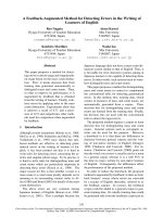
be grouped under design (57), construction (23) and maintenance (27) phases.
Fig. 5.1 Schematic diagram of electrical system of commercial building (Siemens, 2008)
Table 5.8 Maintainability factors for electrical system and their RWs
Component
Maintainability
factors
Critical defect
mitigated
Non-critical
defect mitigated
Wt. RW
Design phase
h1 Capacity H2 0.191 0.005
h2 Phase H2 0.191 0.005
h3 Location H12 0.186 0.005
System in
general
h4 Label / notice H12 H6, H18 0.247 0.006
150
Component
Maintainability
factors
Critical defect
mitigated
Non-critical
defect mitigated
Wt. RW
h5 Selection H2, H3, H9, H10, H11,
H13, H21
H8, H22 1.193 0.029
h6 Mounting H8 0.032 0.001
h7 Location H8 0.032 0.001
h8 Access H11, H12 0.326 0.008
h9 Room design H9, H11, H12 H8 0.358 0.009
Transformer
h10 Noise reduction H8 0.032 0.001
h11 Material HI, H13, H16 0.829 0.020
h12 Size H1, H2, H5, H13, H16 1.299 0.031
h13 Cable selection H1, H2, H13, H16 H14 1.053 0.026
h14 Insulation H1, H2, H13, H16 1.020 0.025
h15 Joints H15 0.189 0.005
h16 Thermal effect H1, H2, H4, H13, H16,
H27
H18 1.427 0.035
h17 Physical
protection
H6, H14 0.066 0.002
h18 Laying method H5 H14 0.313 0.008
h19 Buswasy select H1, H2, H5, H13, H16 1.299 0.031
h20 Location H13 H14 0.357 0.009
Cable &
wiring
h21 Layout H1, H2, H4, H13, H16 H18 1.216 0.029
h22 Join /pull box H6, H14, H17 0.101 0.002
h23 Splice H5, H15 0.469 0.011
h24 Termination H5, H15 0.469 0.011
h25 Gen. spec. H19 H18, H23 0.272 0.007
h26 Housing H3, H4, H19, H20 H18, H23 0.899 0.022
h27 Switchboard H18 0.029 0.001
h28 Panelboard spec H19 0.210 0.005
h29 Panelboard nos. H3 0.181 0.004
h30 Elec. rm. / closet H4 H18 0.197 0.005
h31 Outlet box H20 0.279 0.007
h32 Switch H23 0.033 0.001
h33 Receptacle H20 H22 0.305 0.007
h34 Short-circuit
protection
H1, H13, H16, H27 H7, H24, H31 1.136 0.028
Connector
h35 Ground fault H4, H16 H18 0.488 0.012
h36 Aesthetics H28 0.211 0.005
h37 Flexibility H28 0.211 0.005
h38 Maintainability H28 H30 0.245 0.006
h39 Lamp selection H28 H29 0.237 0.006
Lighting
h40 Ballast selection H32 0.041 0.001
h41 Source selection H33, H35, H36 0.460 0.011
h42 Housing H33, H36 0.348 0.008
h43 Generator
selection
H33, H35, H36 0.460 0.011
h44 Control H36 0.144 0.004
h45 Battery selection H36 0.144 0.004
Standby &
Emergency
power
h46 Battery
discharge
H36 0.144 0.004
h47 Shape H38 0.125 0.003
h48 Conductor H38 H37 0.153 0.004
h49 Electrode H38 H37 0.153 0.004
h50 Location H38 H39 0.254 0.006
h51 Networking H38 0.125 0.003
Grounding
h52 Access H38 H39 0.254 0.006
h53 Shape H38 0.125 0.003
h54 Material H38 H37 0.153 0.004
h55 Joint H38 H37 0.153 0.004
LPS
h56 Fastener H38 H37 0.153 0.004
Ancillary
facility
h57 Coordination H15, h28 H39 0.529 0.013
Design subtotal 0.527
151
Component
Maintainability
factors
Critical defect
mitigated
Non-critical
defect mitigated
Wt. RW
Construction phase
h58 Inspection H11, H12 H8 0.358 0.009 Transformer
h59 Elec. test H2, H3 0.371 0.009
h60 Prep. H1, H13, H16 H14 0.719 0.017
h61 Pulling H15, H16 H14 0.513 0.012
h62 Jointing H1, H13, H15, H16 H14, H17 1.087 0.026
h63 Protection H5, H15 H14 0.502 0.012
Cable
h64 testing H2 0.191 0.005
h65 Prep H1, H13, H16 H14 0.862 0.021
h66 Install H1, H13, H15, H16 1.018 0.025
Busway
h67 Testing H2 0.191 0.005
h68 Wiring H2, H4, H25 H18 0.721 0.017
h69 Connection H4, H5, H25 H14, H17, H18 0.878 0.021
Dist. & prot.
device
h70 Testing H2, H16 H14, H17 0.550 0.013
h71 Fixing H32 0.041 0.001 Lighting
h72 Testing H29 0.034 0.001
h73 Gen. Install H33, H36 0.348 0.008
h74 Generator
commissioning
H33, H36 0.348 0.008
Standby &
emergency
power
h75 Battery install H36 0.144 0.004
h76 Prep. H38 H37 0.153 0.004
h77 Install H38 H39 0.254 0.006
Grounding
h78 Test H38 0.125 0.003
LPS h79 Install H38 H37 0.153 0.004
h80 Test H38 0.125 0.003
Construction subtotal 0.235
Maintenance phase
h81 Clean H9, H11, H12 H8 0.358 0.009
h82 Check H9, H10, H11 H8 0.288 0.007
Trans-
former
h83 Test H11 0.140 0.003
h84 Clean H15, H16 H14 0.513 0.012 Wiring
h85 Check H14, H17 0.069 0.002
h86 Clean H18 0.029 0.001
h87 Check H14, H17 0.069 0.002
Distr.
Equipment
h88 Test H24 0.029 0.001
h89 General H3, H25 0.514 0.012
h90 CB H1, H3, H13, H16, H25 1.343 0.033
h91 Fuse H1, H3, H13, H16 1.010 0.024
Protective
equipment
h92 GFCI H13, H16, H25 0.948 0.023
h93 Clean H28, H35 0.323 0.008
h94 Check H27, H28 H30, H31, H32 0.531 0.013
Lighting
h95 Replace H27, H28 H31 0.456 0.011
Standby
power
h96 Check H36 H34 0.142 0.003
h97 Clean H36 H34 0.142 0.003
h98 Check H33 0.203 0.005
Generator
h99 Test H35 0.113 0.003
h100 Clean H36 0.144 0.004
h101 Check H36 0.144 0.004
Battery
h102 Calibrate &
test
H36 0.144 0.004
h103 Check H38 H37 0.153 0.004 Grounding
& LPS
h104 Test H38 H39 0.254 0.006
h105 Building age H4, H5, H12, H25, H38 H18, H30 1.155 0.028
h106 Use H22, H23 0.058 0.001
Ext. factors
h107 Vandalism H12 H14,H18,H22,
H23, H39
0.560 0.014
Maintenance subtotal 0.238
Total 1.000
152
5.11 Maintainability scoring for fire protection system
The prime objective of fire protection system is to save life and property by prevention,
detection, control and suppression of fire. For this purpose the main components falling under
fire protection system are detector, communicator, sprinkler, hydrant, hose and portable fire
extinguishers. For a safe and panic-free evacuation the escape route should be fortified with
fire door, standby power supply and pressurization system for smoke control. Active fire
protection system is covered by the scope of this research. As these elements are used only
during emergency, they bear a high probability of being overlooked unless the mishap occurs.
Design and installation of the system is strictly standardized by the statutory body. Hence the
maintainability guidelines (Table 5.9, Appendix C.9) are primarily based on local SCDF code
(2007). To mitigate defects (Table 4.20) in fire protection system, a total of 90 factors were
identified: 39, 20 and 31 are related to design, construction and maintenance respectively.
Table 5.9 Maintainability factors for fire protection system and their RWs
Component Maintainability factors
Critical defect
mitigated
Non-critical dfct.
mitigated
Wt. RW
Design phase
j1 Performance J1 0.251 0.015
j2 Applicability J1 0.251 0.015
Detector
j3 Mounting J1 0.251 0.015
j4 Selection J3 0.027 0.002
j5 Location J3 0.027 0.002
Alarm
j6 Connectivity J4 0.046 0.003
j7 Location J4 0.046 0.003
j8 Legibility J3, J4 0.027 0.002
j9 Indicator J3 0.073 0.004
j10 Safety J4 0.046 0.003
j11 Connectivity J4 0.046 0.003
Alarm panel
j12 Power supply J2, J3, J4 0.106 0.006
j13 Location J4, J6 0.083 0.005
j14 Security J6 0.002
j15 Material J6, J8 J8 0.004
Hydrant
j16 Supply J8 0.002
j17 Cabinet location J11 0.120 0.007
j18 Cabinet spec. J11 J12 0.161 0.009
Hosereel
j19 Hose J10 0.194 0.011
j20 Selection J14 0.209 0.012
j21 Location J15 0.152 0.009
j22 Material J16, J17 J20, J21 0.403 0.024
j23 Support J18 0.032 0.002
j24 Water quality J16 J21, J25 0.264 0.016
Sprinkler
j25 Pump location J19 0.135 0.008
j26 Selection J29 0.182 0.011
j27 Location J26 0.234 0.014
Portable fire
extinguisher
j28 Quality J26, J28 J30 0.464 0.027
Fire door j29 Selection J32 0.048 0.003
153
Component Maintainability factors
Critical defect
mitigated
Non-critical dfct.
mitigated
Wt. RW
j30 Operation J31 0.221 0.013
j31 Detailing J31 J32 0.269 0.016
j32 Marking J32 0.048 0.003
j33 Power supply J34 0.175 0.010
j34 System selection J34 0.175 0.010
j35 Lamp selection J34 0.175 0.010
j36 Battery discharge J34 0.175 0.010
j37 Battery location J34 0.175 0.010
Escape
lighting
j38 Charger J34 0.175 0.010
Smoke ctrl. j39 Safety & back-up J36 0.116 0.007
Design subtotal 0.337
Construction phase
j40 Wiring J2, J4 0.079 0.005
j41 Mounting J1 0.251 0.015
Detector &
alarm
j42 Testing J1 0.251 0.015
j43 Storage J6 0.037 0.002
j44 Install J5, J6 0.082 0.005
Hydrant
j45 Testing J7 J6, J8 0.266 0.016
j46 Base work J11 0.120 0.007 Hosereel
j47 Commissioning J10, J11 0.314 0.018
j48 Mounting J15 0.152 0.009
j49 Support J15 J18 0.184 0.011
Sprinkler
j50 Supply network J17, J19 J21, J24 0.345 0.020
j51 Mounting J27, J30 0.070 0.004 Portable
extinguisher j52 Protection J26, J28 0.427 0.025
j53 Storage & handling J31 0.048 0.003
j54 Fixing J31 0.221 0.013
Fire door
j55 Checking J31 0.221 0.013
j56 Fixing J34 0.175 0.010
j57 Marking J34 0.175 0.010
Light
j58 Testing J34 0.175 0.010
Smoke ctrl. j59 Install J36 0.116 0.007
Construction subtotal 0.218
Maintenance phase
j60 Clean J1 J4 0.297 0.017
j61 Test J1 J4 0.297 0.017
Detector &
alarm
j62 Check & record J2, J3, J4 0.106 0.006
j63 Clean J6, J8 0.072 0.004
j64 Check J6, J9 0.076 0.004
Hydrant
j65 Test & record J6 0.037 0.002
j66 Clean J11 0.120 0.007
j67 Check J10, J11 0.314 0.018
Hosereel
j68 Test J10 0.194 0.011
j69 Clean J14, J15 0.361 0.021 Sprinkler
j70 Check J14, J15 0.361 0.021
j71 Clean J16, J17 0.345 0.020
j72 Check J16, J19 J20, J23 0.396 0.023
Supply
j73 Test J19 0.135 0.008
j74 Clean J21, J24, J25 0.106 0.006
j75 Check J21,J22,J23, J24,J25 0.149 0.009
Valves
j76 Test J21, J24, 0.080 0.005
j77 Check J26, J28, J29 J27, J30 0.679 0.040
j78 Replace / recharge J28, J29 0.374 0.022
Portable
extinguisher
j79 Test & record J28 0.193 0.011
j80 Clean J31, J33 J32 0.448 0.026
j81 Check & record J31 J32 0.269 0.016
j82 Lubricate J33 0.178 0.010
Fire door
j83 Repair & replace J32 0.048 0.003
j84 Clean J34 0.175 0.010 Lighting
j85 Check & record J34 0.175 0.010
154
Component Maintainability factors
Critical defect
mitigated
Non-critical dfct.
mitigated
Wt. RW
j86 Calibrate & test J34 0.175 0.010
Smoke ctrl. j87 Check & test J36 J35 0.151 0.009
j88 Building age J10, J33 J18, J21 0.439 0.026
j89 Level of usage J31 J32 0.269 0.016
External
factors
j90 Vandalism J26, J28 J13, J22, J24 0.548 0.032
Maintenance subtotal 0.445
Total 1.000
5.12 Overview of scoring of all subsystems
For the entire building a total of 731 guidelines were proposed (Table 5.10). Design related
guidelines were undoubtedly maximum in number (52.26% in average). But construction had
75.6% higher emphasis for C&A subsystems while maintenance guidelines had 104.4%
greater influence for M&E subsystems.
Table 5.10 No. of maintainability factors
Design Construction Maintenance
System Sub-system
Total No. % No. % No. %
C&A Basement 63 30 47.62 24 38.10 9 14.29
Facade 79 42 53.16 26 32.91 11 13.92
Wet area 59 32 54.24 18 30.51 9 15.25
Roof 64 35 54.69 21 32.81 8 12.50
Avg. 66.25 34.75 52.43 22.25 33.58 9.25 13.99
M&E San-plumb. 93 49 52.69 25 26.88 19 20.43
HVAC 92 54 58.70 12 13.04 26 28.26
Elevator 84 44 52.38 10 11.90 30 35.71
Electrical 107 57 53.27 23 21.50 27 25.23
Fire prot. 90 39 43.33 20 22.22 30 33.33
Avg. 93.20 48.60 52.07 18.00 19.11 26.40 28.59
Entire building 731 382 52.26 179 24.49 169 23.12
5.13 Summary
Based on the findings in defect analysis, total 731 maintainability aspects or factors were
developed and grouped under life cycle phases of subsystems and then under components.
The corresponding scores of their various options are based on its ability to achieve higher
maintainability by mitigating defects. The derived relative weights of the factors denote their
relative importance as maintainability contributor within the subsystem. This whole process
benchmarks selection of existing design, construction and maintenance guidelines by linking
them through their long term impact. Hence the second objective of this study was achieved.
This knowledge will be used in next section to find maintainability score in COMASS.
Chapter 6 Comprehensive Maintainability Scoring System
6.1 Introduction
Comprehensive maintainability scoring system or COMASS is the third phase of this research
addressing the third objective and together with criticality analysis provides answer for the
second research question. It is the integration of nine major building subsystems. Their
relative weights (more precisely global weights or GW w.r.t overall building maintainability)
were generated by analyzing the AHP (analytic hierarchy process) questionnaires. The local
weights (LW) at each level of hierarchy reflected the grading logic of the decision makers
(DM) and were compared with the subjective knowledge shared by them during interview.
6.2 Data analysis
Data analysis in AHP includes: data processing, dealing with inconsistency, aggregation of
results into group decision making (GDM) and derivation of GWs. Their methodology has
been discussed in detail in Section 3.4.6. It also illustrates how aggregation of individual
priorities (AIP) using geometric mean method (GMM) was found most suitable for this
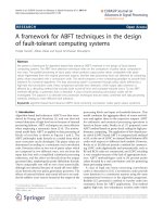
research. Fig. 6.1 shows the demography of the DMs who provided valid responses.
Work profile
Ow ner &
Developer
18 (49%)
FM Company
16 (43%)
Individual
3 (8%)
Years of experience
10-15 Yrs.
9 (24%)
15-20 Yrs.
8 (22%)
> 20 Yrs.
10 ( 27%)
5-10 Yrs.
10 (27%)
Fig. 6.1 Demography of the respondents
6.2.1 Data processing in ExpertChoice (EC 11.5)
Compared to other available softwares, EC works in tandem with AHP (Bodin & Gass, 2003).
In EC, it is easy to construct the hierarchy and instantaneously check the important
information such as inconsistency ratio (IR) and LW. First the master template of hierarchy
155
a. Hierarchy for building maintainability
b. Auto generation of Inconsistency Ratio (IR)
c. Local weights (LW) generated in EC
Fig. 6.2 Data processing in Expert Choice (EC)
156