Hydroelastic responses and interactions of mega floating fuel storage modules 1
Bạn đang xem bản rút gọn của tài liệu. Xem và tải ngay bản đầy đủ của tài liệu tại đây (7.12 MB, 28 trang )
1
CHAPTER ONE
Introduction
‘’ World population is projected to grow from 6.1 billion in 2000 to 8.9 billion in 2050,
increasing therefore by 47 per cent.”
United Nations, 2004
The growth in urbanisation due to the continuous increase of world population and
rural-urban migration problem has exerted great pressure on the urban cities. The
American Association for the Advancement of Science (AAAS) 1996 annual meeting
has reported that about two-third of the humanity are crowded in the coastal cities
resulting in these cities becoming over-developed, over-crowded and over-exploited.
Ultra high-rise structures as well as underground space solution are sought in order
to fully utilise the lands in these highly urban cities. However, with the world
population growth keeps on expanding at an alarming rate and expected to reach
75% of the humanity by year 2025 (AAAS annual meeting, 1996), land scarcity
problems are expected to increase dramatically in the near future. The conventional
way of expanding the land mass for land scarce countries such as Japan, the
Netherlands, Monaco and Singapore through aggressive land reclamation programs
Introduction
2
are not cost effective or even feasible as the water depth gets larger than 20m or
when the seabed is extremely soft. Moreover, land reclamation works generally have
a negative environmental impact on the coastlines and the marine eco-system.
Upadhayay et al. (2002) and Padma (2004) claimed that the mangrove forest that
plays a significant role in reducing the devastating impact of tsunamis that struck the
southern India on 26 December 2004 is among the most threatened habitat in the
world due to deliberate land reclamation for urban and industrial development. The
Reef Ecology Study Team of NUS also reported that Singapore has lost up to 65% of
their live coral cover since 1986 due to major land reclamation activity.
As a solution to pursuing environmental friendly yet sustainable technology in
creating additional land, Japanese engineers have propounded the construction of
Very Large Floating Structure (VLFS) – a technology that allows the creation of
artificial land from the sea without destroying marine habitats, polluting coastal
waters and altering tidal and natural current flow (Wang et al., 2008). VLFSs have
advantages over the traditional land reclamation solution in the following respects:
they are cost effective when the water depth is large and the seabed is soft;
environmentally friendly as they do not damage the marine eco-system, or silt-up
deep harbours or disrupt the ocean currents; they are easy and fast to construct and
therefore the investment may be monetised more rapidly; they can be easily
removed or expanded; and the structure on VLFS is protected from seismic shocks
since VLFSs are inherently base isolated. Examples of these pontoon-type VLFS are
the Mega Float (a runway test model in Tokyo Bay, see Fig. 1.1a), the emergency
Introduction
3
rescue bases (moored at Tokyo Bay, Ise Bay and Osaka Bay), the floating oil storage
bases (in Shirashima and Kamigoto Islands, see Fig. 1.1b), the floating ferry piers (at
Ujina Port, Hiroshima, see Fig. 1.1c), the floating bridges (in Dubai, UAE and Seattle,
USA, see Fig. 1.1d) and the floating performance stage (at Marina Bay, Singapore, see
Fig. 1.1e).
(a) Mega-Float at Tokyo Bay, Japan
(b) Floating oil storage base at Kamigoto
Island, Japan
(c) Floating ferry pier at Ujina Port,
Hiroshima, Japan
(d) Lacey V. Murrow Bridge and the
Third Washington Bridge at Seattle, USA
(Photo courtesy of Prof. E. Watanabe -
Kyoto University)
(e) Floating performance stage at Marina Bay, Singapore
Fig. 1.1 Applications of pontoon-type VLFSs
Introduction
4
The application of VLFSs as floating farms in urban cities may also emerge as an
innovative solution to provide arable land in supplying food to the increasing growth
of human population while maintaining the integrity of the ecosystem. The
sustainable engineering science barge (Fig. 1.2a) – a prototype floating urban farm
powered by sustainable energy that raises vegetables through water-saving
hydroponic technology, is constructed by the New York Sun Works Center on the
Hudson River in Manhattan to demonstrate that urban agriculture on floating
structure is possible without causing damage to the environment. In salmon
producing countries such as Norway, the United States of America, Canada and Chile,
marine salmon farm (Fig. 1.2b) – a floating structure of one to twenty individual
netpens (cages) that is anchored relatively close to shore, is constructed to ensure
continuous supply of fresh fish even during the off-season of the species (Per
Heggelund, 1989).
(a) Sustainable engineering science
barge at Hudson River, Manhattan, USA
(source: )
(b) Salmon farms north of Vancouver, Canada
(source: )
Fig. 1.2 Application of VLFSs as floating farms
Introduction
5
With the increase in the human population coupled with land-scarcity in cities
and global warming problems, VLFS technology has emerged as a new option for
future human habitation. The Lilypad Floating Ecopolis (Fig. 1.3a), proposed by the
Belgium architect Vincent Callebaut, is an example of a visionary proposition to
house part of the city population in a huge floating city. With more than half of the
Netherlands’s land area now below sea level, the Dutch have also proposed the
concept of a floating town (Fig. 1.3b), which is a visionary integrated town consisting
of greenhouses, commercial centre and residential area. Prof. Wang Chien Ming from
the National University of Singapore has also proposed the use of VLFS as a
floating-type cruise terminal (Fig. 1.3c) and a mega floating crab restaurant (Fig. 1.3d)
as opposed to the conventional onshore design in order to create iconic structures
for Singapore to attract tourists
.
The examples shown above show that the feasibility of using the VLFS
technology as an attractive alternative to create additional lands for development. In
this thesis, we will focus on the use of VLFS for storing fuel in the sea. Inspired by the
successful construction and operation of the floating oil storage bases in Kamigoto
and Shirashima Islands in Japan, Singapore is proposing the use of an offshore-based
floating fuel storage facility (FFSF) to expand her fuel storage capacity. The role of
Singapore as the 3
rd
largest oil hub in the world and the advantages of the
offshore-based floating fuel storage facility will be further discussed in the following
section.
Introduction
6
(a) Lilypad floating ecopolis
(source: www.vincent.callebaut.org)
(b) Visionary semi-aquatic town in the Netherlands
(source: )
(c) Proposed floating cruise terminal in
Singapore
(d) Proposed mega floating crab
restaurant in Singapore
Fig. 1.3 Proposed future VLFSs
Introduction
7
1.1 Focusing on VLFS as Floating Fuel Storage Facility (FFSF)
“Race is on to build storage facilities and add capacity
Amid the huge global demand for oil, Singapore as the world’s 3rd largest trading
hub has hit a snag – where to put the stuff? Its storage facilities are almost full and
while additional space is coming up, the problem will resurface, an industry expert
has warned…“
The Straits Times, 18 July 2005, page H21
World’s trade and development have increased rapidly with globalisation triggered
by the information, communication and transportation technology. Correspondingly,
the demand for oil consumption has increased sharply. Being the 3
rd
largest oil hub in
the world, Singapore is facing an urgent need to increase its oil storage capacity with
all the land for oil tank farms being almost exhausted. Its conventional land-based oil
tank farms are not amenable for further expansion due to land scarcity. Industry
feedback has indicated that Singapore is at least 3 million cubic metres shortage of
oil storage, which would require more than 100 hectares of land to accommodate
(Yap, 2008). Innovative underground cavern-type storage facility for crude oil is
currently being constructed in Jurong Island, Singapore. Yet, more storage capacity
for fuel is needed. This need prompted the consideration of the floating type fuel
storage facilities.
Introduction
8
The presence of sterile sea spaces around various islands in Singapore makes the
floating offshore storage facilities an enticing alternative. A joint research project
between Jurong Town Corporation (JTC), Maritime and Port Authority (MPA) and the
National University of Singapore (NUS) was conducted with the objectives of
producing a practical yet cost effective floating fuel storage system. The proposed
floating fuel storage facility comprises mega box-like floating storage modules that
are placed side-by-side and held in position by mooring dolphin-rubber fender
system to restrain its horizontal movement but allowing vertical movement with the
waves and tidal changes, as well as with the varying payloads. Floating breakwaters
such as the one found in the Kanon Marina in Hiroshima, Japan (see Fig. 1.5) could
be constructed around the floating storage modules in order to attenuate the wave
forces. The floating breakwater can also double up as an oil fence as well as acting as
a collision barrier.
Fig. 1.4 Design concept of floating fuel storage facility (Picture courtesy of Jurong
Consultants Pte. Ltd.)
Introduction
9
Fig. 1.5 Floating concrete breakwaters at Kanon Marina, Hiroshima
The feasibility studies for the FFSF, co-funded by JTC, MPA and NUS, have
reported that for the storage of 300,000 cubic metres, the FFSF only requires 5
hectares of foreshore land, a significant reduce of land by 4 times as compared to
that required for the land based storage facility (Yap, 2008). Moreover, such floating
storage facilities also assist in providing relief to tanker traffic congestion and
crowded anchorage spaces at Singapore harbours since these floating fuel storage
facilities may double up as a bunkering cum mooring station for ships. The FFSF also
has the advantages of scalability and mobility. Should the storage capacity of the
FFSF needs to be increased, more storage modules may be added. It can also be
easily dismantled, removed or even relocated elsewhere. The floating structures
being afloat in the sea are also environmental friendly as they do not affect the water
quality and disrupting the water flow underneath the floating modules as well as
causing irreversible damage to the marine habitat.
Floating
concrete
breakwaters
Introduction
10
The FFSF does not only augment the oil storage capacity significantly but it also
increases its waterfront for oil carriers and bunker ships. The construction of the FFSF
next to the land-based pumping control station will serve as the hub between the
floating modules and the fuel supply vessels. Petrochemical products such as
processed and/or crude oil and feedstock petrochemicals (e.g. ethylene, benzene,
etc.) may also be stored in the floating modules. This cutting-edge innovation by
using the VLFS as a floating storage facility will continue to aid in bolstering the
country’s standing in the oil trading and bunkering industry.
The storage of hydrocarbon and petrochemical out in the sea by ultilising the
VLFS technology raises wonderful challenges in the design of the FFSF. As FFSFs have
a large surface area and a relatively small depth, they behave elastically under wave
action. The fluid-structure interaction has been termed as hydroelasticity.
Hydroelastic analysis that takes into account the elastic vibration modes of the
structure is thus necessary to be carried out for the FFSF in order to assess the
dynamic motion and stresses due to wave action for design (Suzuki and Yoshida,
1996). This PhD thesis focuses on the hydroelastic responses and interactions of two
box-like floating storage modules by using the frequency domain approach. The
hydroelastic interaction behaviors of the floating storage modules when they are
placed side-by-side are critical factors that affect the responses of the structures
under wave actions. The interactions between the modules under different loading
combinations might also affect the loading/offloading operations. Besides that, the
enhanced wave elevations along the channel formed by the adjacently placed
Introduction
11
floating storage modules are important to know in order to design the draft and
freeboard of the storage modules so that green water that adversely affects the
stability of the storage modules does not occur. A suitable channel spacing has to be
determined in order to minimise the structural responses and at the same time
maximise the loading capacity of the storage modules in a confined sea space. This
channel spacing should not be too large as the numbers of mooring system will
increase or too small as this increases the structural responses and interactions. The
second order drift forces acting on the floating storage modules (by taking into
account the interaction behaviors) are also crucial in designing the mooring dolphin
fenders.
Before embarking on the contents on these studies, we shall provide a literature
survey on the recent development that has been carried out on the aforementioned
research areas as well as to highlight the gaps in the research so as to provide the
backdrop for the ensuing study. The objectives and scope of this PhD thesis will then
be presented in Section 1.3.
1.2 Literature Review
In Section 1.2.1, the literature reviews on the background and development of the
hydroelastic analysis will be first presented. In Section 1.2.2, we then proceed to
review the accuracy in predicting the deflections and stress resultants on the VLFS by
modelling the VLFS as a plate using the classical thin plate theory and Mindlin plate
theory. The use of the modified non-conforming quadratic-serendipity (NC-QS)
Introduction
12
Mindlin plate element in modelling the VLFS that provides a better prediction to the
stress resultants will also be proposed. In Sections 1.2.3 and 1.2.4, some literature
surveys will then be made on the hydroelastic interactions of two floating storage
modules placed side-by-side and the wave propagations along the channel formed
by the two floating storage modules. The steady drift forces on the two adjacently
placed floating storage modules are also reviewed in Section 1.2.5.
1.2.1 Background on Hydroelastic Analysis
In the hydrodynamic analysis of a floating body under wave action, the water is
usually assumed to be an ideal fluid, i.e. inviscid and incompressible, and its motion
is irrotational so that the fluid motion could be represented by the velocity potential.
The fluid velocity potential that satisfies the Laplace equation has to be first
computed in order to solve for the motion of the floating body. The conventional
method of solving the velocity potential is to convert the Laplace equation into a
boundary value problem. The boundary conditions are the Neumann condition at the
seabed and the wetted surface of the floating body, the linearised free surface
condition and the radiation conditions at infinity. The earliest solution to this
boundary value problem was given by John (1949, 1950), in which he used the Green
function within a boundary integral formulation to solve for the wave scattering from
floating bodies. A detail description of the linear wave theory was published by
Wehausen and Laiton (1960) in their remarkable review article ‘Surface Waves’. This
review article contains benchmark solutions for wave-structure interactions
Introduction
13
problems (Newman, 1977, 1985 & 1994; Noblesse, 1979; Chakrabarti, 1988; Mei,
1989). However, earlier works by these researchers only considered the floating
structure as a rigid body. With the increasing interest in VLFS as one of the future
solutions to creating land for land-scarce countries, hydroelastic analysis on floating
structure emerged as a new research area in the early 1990s. To name a few, among
the pioneers working on the hydroelastic theory of VLFS are Ertekin and Riggs (1993),
Suzuki (1996, 2005), Yago and Endo (1996), Kashiwagi (1998, 2000), Utsunomiya et al.
(1998) and Ohmatsu (1998, 1999). The development of hydroelastic theory should
also be attributed to Meylan and Squires (1996) and Meylan (1997, 2000) who
studied ice-floe problems but these problems were similar to VLFS problems. The
numerical schemes presented by these researchers are of significance importance in
developing our numerical model for the hydroelastic analysis and interactions of
floating fuel storage modules placed side-by-side. A more in-depth review on the
modelling of VLFS for the hydroelastic analysis will be given in the next section.
1.2.2 Modelling of VLFS for Hydroelastic Analysis
The common approach in modelling the VLFS for the hydroelastic analysis is by
modelling the entire floating structure as a single solid plate based on the Kirchhoff
plate theory and zero-draft assumption (Watanabe et al., 2004). The solid plate could
well represent the actual VLFS due to the fact that the VLFS has a relatively large plan
area as compared to its depth. The deflections on the solid plate predicted by the
Kirchhoff plate theory are proven to be of very high accuracy as reported by
Introduction
14
Kashiwagi (1998), Utsunomiya et al. (1998), Hermans (2000), Meylan (2001) and
Watanabe et al. (2000). However, the stress resultants (such as the twisting moments
and shear forces) are not accurately predicted and they do not satisfy the free-edge
boundary conditions (Wang et al., 2001). The inaccuracy is due to the stress
resultants being computed from second and third derivatives of the approximate
deflections. In addition, the effects of shear deformation and rotary inertia are
neglected in the classical thin plate theory. Also, these effects become significant in
high frequencies of vibration and should be included when the floating structure is
subjected to wavelength shorter than twenty times the thickness or when the
thickness-length ratio of the floating structure is greater than 0.005 as reported by
Mindlin (1951) and Petyt (1990). As the mega floating storage module such as the
one shown in Fig. 1.4 has a larger thickness to length ratio compared to the
pontoon-type VLFS, the classical thin plate theory could no longer predict the
deflections and stress resultants correctly. Furthermore, the zero-draft assumption
made on the VLFS in the hydroelastic analysis could no longer be applied to the FFSF
due to its larger draft under loaded condition. The hydroelastic responses based on
the zero-draft assumption are found to be inaccurate when the draft of the floating
modules gets larger or when the VLFS is operating in shallow water condition (Suzuki
et al., 2006; Riggs et al., 2008).
Watanabe et al. (2000) adopted the Mindlin plate theory (thick plate theory)
where the motion of the plate is represented not only by its deflection but also its
bending rotations. They derived an exact hydroelastic solution for a circular VLFS
Introduction
15
under wave action. Recently, Wang and Wang (2006) used the 4-node Mindlin plate
element to model the elastic plate. Computational results from Wang and Wang
(2006) agreed well with the exact solution. They found that the predicted stress
resultants better satisfy the free-edge natural boundary conditions when compared
to the Kirchhoff plate. However, on closer examination of the transverse shear forces,
it was found that these forces do not vanish completely at the free edges of the
plates as they should.
Kim and Choi (1992) and Bathe (1996) investigated the inadequacy of the
numerical Mindlin plate model in obtaining the correct shear forces distribution as
the thickness of the plate gets smaller. Hence the plate does not bend easily due to
excessive shear stiffness on the plate. Such a phenomenon is known as shear locking
and it prevents the stresses from vanishing at the free edges. To overcome the shear
locking problem, Bathe (1996) suggested the use of reduced integration, selective
interpolation or mixed interpolation methods that will increase the flexibility of the
element. In contrast, Choi (1986) superposed non-conforming modes on the basis
functions of a 9-node element in order to restore the real flexural deformation to
avoid shear locking phenomena. Kim and Choi (1992) claimed that their 9-node
element can avoid shear locking phenomenon when the interpolated shear strain
function contains more variables than the number of equations obtained. This means
that either the number of variables has to be increased or the number of equations
relating the shear strains has to be decreased. Therefore, they proposed the coupling
of reduced integration method with additional non-conforming modes.
Introduction
16
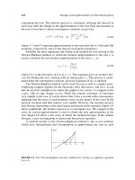
Note that the Kirchhoff plate theory assumes that the normal to the middle
surface remains normal to the deformed surface. This assumption is tantamount to
neglecting the effect of transverse shear deformation. This means that shear force
has to be calculated from the equilibrium equation since it is zero if calculated from
the constitutive relation. Thus, the shear force expression in the Kirchhoff plate
theory involves the third derivative of the transverse deflection which of course will
not be accurate. Unlike the Kirchhoff plate theory, the Mindlin plate theory allows
the normal to the undeformed middle surface to rotate (albeit in a constant rotation)
with respect to the deformed midsurface. This assumption admits a constant shear
strain and hence a constant shear stress through the plate thickness. In order to
compensate for the error due to the violation of the statical condition of zero stress
at the free surfaces, a shear correction factor is introduced to factor the shear force
in the Mindlin plate theory (given later as
2
κ
in the Mindlin plate theory Eqs.
2.9a-c). Notwithstanding, the shear force expression in the Mindlin plate theory
involves the constant bending rotation
x
ψ
,
y
ψ
(which is a new variable) and only
the first derivative of the deflection function (see Eqs. 2.13c in Chapter 2). So it is
clear that the shear forces calculated using the Mindlin plate theory should be more
accurate than its Kirchhoff plate counterpart. Therefore, the methods proposed by
Kim and Choi (1992) and Bathe (1996) are highly contributory in predicting the stress
distribution on the slabs of the mega floating fuel storage modules correctly. In order
to reduce the computational time, their modified 9-node element could be simplified
to an 8-node element without loss of accuracy in the stress distribution. This
Introduction
17
designated 8-node NC-QS Mindlin plate element will be used in modelling the
floating storage modules in order to access the hydroelastic responses and
interactions behaviour of the floating storage modules when they are placed
side-by-side.
1.2.3 Hydroelastic Responses and Interactions of Adjacently Placed Floating
Modules
Extensive hydroelastic analyses had been carried out on the VLFS under wave actions
by modelling the floating structure as a solid plate as presented in the previous
section. The hydroelastic responses computed on the equivalent solid plate were
found to be in good agreement with the experimental test results (Yago and Endo,
1996; Kashiwagi, 1998; Utsunomiya, 1998). However, there have been relatively few
studies conducted on the hydroelastic responses and hydrodynamic interactions of
multiple VLFS when they are placed side-by-side and with the presence of floating
breakwater. Koo and Kim (2005) studied the hydrodynamic interactions between the
adjacent storage modules of LNG gas terminals in the Gulf of Mexico, but their
calculations were carried out by assuming rigid body motions of the floating
structures, i.e. neglecting the elastic deformations of the modules. They found that
the safety and operability of the side-by-side loading and offloading operation are
greatly influenced by the relative motions between the adjacent modules due to
wave action.
Introduction
18
A comprehensive review on the research and development of the Mega-Float
project from 1995-2001, as well as its legal aspect and environment impact have
been reported by Suzuki (2005). Ohmatsu (2000) presented an effective method for
calculating the wave induced hydroelastic response of a pontoon-type VLFS when the
VLFS is near a breakwater. Based on his study, he found that the response of the VLFS
decreases when the reflected coefficient of the breakwater is small. Utsunomiya et al.
(1998) also presented a wave response analysis of a box-like VLFS near a breakwater
by employing the higher order boundary element method (HOBEM). The influence of
a breakwater on the response was determined and its effectiveness in reducing the
response of the VLFS was confirmed. However, these researchers have not studied
the hydrodynamic interactions of the floating storage modules when placed adjacent
to each other and with floating breakwaters in place. It is to be noted that the
breakwater considered in the previous researchers’ studies are of the
bottom-founded type. In the literature, there are studies focusing on the
hydrodynamic properties of floating breakwaters by treating the breakwater as a
separate part of the structure instead of investigating the influence of floating
breakwater towards the response of the floating structures. Therefore, investigations
on the hydroelastic responses and interactions of the adjacently placed floating
storage modules enclosed by floating breakwater are the focus of the present study.
Introduction
19
1.2.4 Wave Propagation along Channel Formed by Two Adjacently Placed
Floating Modules
While the hydroelastic interactions between the floating storage modules are
significant towards the structural responses as reviewed in the previous section, the
significant effect of the interactions towards the wave field surrounding the floating
structures should not be neglected as well. In the literature, although extensive
research investigations (Molin et al., 2002; Chen, 2004; Chau and Eatock Taylor, 1992;
Issacson and Cheung, 1996; Bai and Eatock Taylor, 2006) have been made on wave
diffraction and radiation by floating bodies such as barges, vessels and cylinders (in
which their motions are dominated by rigid body modes), only a few researchers
such as Wang and Meylan (2002) and Utsunomiya and Watanabe (2006) have
studied the wave reflection by a VLFS under regular wave action. Furthermore, to
date, there have been relatively few studies conducted on wave diffraction and
radiation along the channel formed by VLFS-type floating bodies which are
deformable under wave action. Molin et al. (2002) and Chen (2004) showed that the
free surface elevations are large as the wave propagates through the channel formed
by 2 barges placed side-by-side. The enhanced wave elevations along the channel
formed by the two floating storage modules significantly govern the design of the
floating storage modules. As green water adversely affects the stability of the floating
storage modules, adequate freeboard should be designed when the storage modules
are fully loaded with fuel.
Introduction
20
1.2.5 Steady Drift Forces on Adjacently Placed Floating Modules
When the floating modules are placed close to each other with a relatively small gap,
hydrodynamic interactions between two bodies are expected to be large and
complex. Owing to the hydrodynamic interaction, large repulsion and drift forces may
be exerted on the storage modules, resulting in damage to the mooring system. The
consequences due to the failure of the mooring system when typhoon and tsunami
occurred were addressed by Suzuki (2001). Suzuki (2001) reported that an upper limit
of casualty of 10,000 lives was estimated from the fatal failure scenario of the VLFS
used as a floating airport during heavy storms. This vast numbers of casualty lives
highlight the importance of designing the mooring dolphin system correctly. In doing
so, the steady drift forces have to be computed for the design of the mooring dolphin
fenders.
There are two well known methods for computing the wave interaction
problems which are respectively the near-field method based on the direct pressure
integration method and the far-field method based on the momentum-conservation
principle. Kagemoto and Yue (1986), Chakrabarti (2000), Maruo (1960) and Newman
(1967) applied the far-field method to solve the wave interaction problems. The
far-field method gives only the total forces on all floating modules that are included
by fictitious vertical circular cylinder located far from the ships. The wave interaction
theory proposed by Kagemoto and Yue (1986) and Chakrabarti (2000) is applicable to
any number of modules of arbitrary geometry and in a general spatial arrangement
Introduction
21
with the assumption that the fictitious bottom-mounted vertical cylinder
circumscribing one module does not intersect any part of the other modules (see Fig.
1.6). Kashiwagi et al. (2005) showed that the results of the wave forces in the surge
response may still be accurate although the assumption stated in Fig. 1.6 is violated
but it is not the case for the wave forces in the heave response.
(a) valid
(b) not valid
Fig. 1.6 Validity of the far-field method based on wave interaction theory proposed
by Kagemoto and Yue (1986) (a) Valid when fictitious cylinder circumscribing one
module does not intersect any part of the other module (b) Invalid when the
fictitious cylinder intersects part of the other module
On the other hand, the near-field method proposed by Pinkster (1979) gives
individual forces on each floating structure but the computations are rather
complicated because various components must be evaluated, such as the flow
velocity on the wetted surface of a ship and the relative wave height along the
waterline of a ship (Kashiwagi et al., 2005). Fang and Chen (2002) and Kashiwagi et al.
(2005) adopted the near-field method to compute the interaction of two ships which
are arranged side-by-side in waves. Relative good agreement is found between
Kashiwagi et al.’s (2005) computed and experimental results. As the prediction of the
steady forces on each floating module of the FFSF is a requisite, the near-field
Introduction
22
method must be used.
Analysis of steady drift force acting on a single VLFS by the near-field method
had been carried out by researchers such as Namba et al. (1999) and Utsunomiya et
al. (2001). The numerical scheme presented by these authors could be extended for
the evaluation of steady drift forces acting on adjacently placed mega floating
storage modules.
1.3 Objectives and Scope of Study
The foregoing literature reviews provide insights in identifying the research gaps that
need further investigation for the hydroelastic analysis and design of the FFSF. For the
hydroelastic analysis, we only consider the FFSF that comprises two floating storage
modules placed side-by-side and enclosed by floating breakwater under operation
condition. We used the linear potential wave theory to model the regular wave
whereas the floating fuel storage module is modelled as an equivalent solid plate
without considering the effect of fluid sloshing in the modules towards the
wave-structure interaction.
The objectives of this thesis are to:
i. develop numerical models and solution techniques for solving hydroelastic
interactions problem of very large floating structures
ii. develop robust computer codes in MATLAB that are capable of determining:
• the hydroelastic interaction behavior of adjacently placed floating storage
modules (this knowledge is important for designing the appropriate
Introduction
23
spacing for the modules),
• the flow field especially the wave elevations in the channel formed by the
storage modules (this knowledge is needed to design the necessary
freeboard for the modules to avoid green water on deck), and
• the steady drift forces, allowing for the interaction of floating storage
modules (this knowledge is needed to design the mooring dolphin rubber
fender system).
iii. verify the formulation, solution technique and computer code using existing
results obtained from other researchers as well as to validate the computed
results by carrying out experimental tests of floating structural models in a
water basin.
iv. conduct parametric studies to investigate the effect of:
• floating breakwater, channel spacing, draft, water depth and wave angle
on the responses and interactions of the floating modules
• wave angle, channel spacing, attachment of parapet wall around the
perimeter deck, floating breakwater and water depth on the wave
elevations along the channel
• channel spacing and floating breakwater on the steady drift forces.
Introduction
24
The key developments in the modelling and numerical techniques are summarised
below.
i. Application of thick plate element for modelling the storage modules
Normally, researchers used thin plate elements for modelling the VLFS. In
contrast, we shall adopt the modified NC-QS Mindlin plate element proposed
by Choi (1986) to model the floating fuel storage modules. The advantage of
the NC-QS Mindlin plate element is that it allows a more accurate prediction
of the stress resultants since the spurious modes and shear locking
phenomena are eliminated. The accurate stress distributions are significant in
determining the suitable wall thicknesses of the floating storage modules. It
will be shown herein that hydroelastic analysis carried out using the NC-QS
element is not only accurate in both deflections and stress resultants
computed, but also fast in achieving convergence to the true solution,
thereby greatly reducing the computational time.
ii. Development of numerical model for hydroelastic analysis and
hydrodynamic interactions of floating fuel storage modules
For the first time, the hydroelasic interactions behaviour of the floating
storage modules placed side-by-side will be investigated in detail. The
computed hydroelastic results enable us to design suitable spacings between
the floating modules. A suitable channel spacing is important because if the
spacing is too small, the interactions of the floating modules increase
Introduction
25
significantly and if the channel spacing is too large, the FFSF utilises precious
sea space. The number of mooring dolphins required when the floating
storage modules are placed too far apart will also increase correspondingly,
hence such a design is not cost effective. The behaviour of the floating
modules under different fuel loading combinations will also be studied in
order to determine the suitable loading combinations so as to minimise the
undesirable interaction between the floating modules.
iii. Development of numerical model for wave propagation along channel
formed by two floating storage modules
The developed numerical model would enable us to investigate the effect of
hydroelastic interaction towards the wave elevations along the channel
formed by two floating storage modules. The prediction of the wave runup
due to wave being squeezed in the narrow channel is crucial for the design of
suitable freeboard and draft of the floating storage modules so as to avoid
green water on deck. The wave field surrounding the floating storage
modules could also be computed in order to assess the diffracted and
radiated behavior of the waves as it interacts with the floating modules. This
information could contribute significantly for coastal engineers in
understanding the reflections of waves by deformable floating structures and
its impact towards the coastal erosion especially when the FFSF is located
near shore.