Supported nanosized gold catalysi the influence of support morphology and reaction mechanism 4
Bạn đang xem bản rút gọn của tài liệu. Xem và tải ngay bản đầy đủ của tài liệu tại đây (4.11 MB, 42 trang )
97
Chapter 4
Low Temperature CO Oxidation over TiO
2
-supported Gold
Catalysts -Effect of Hydrothermal Process of TiO
2
Support on Nano
Gold catalysis-
In this chapter, 6 kinds of TiO
2
, including bulk TiO
2
(from Merck), nanotubular (NT)
TiO
2
, and 4 other commercial TiO
2
products, were utilized as the support for gold
nanoparticles. The catalytic performance and kinetics of the carbon monoxide
oxidation reaction over the Au/TiO
2
catalysts were investigated, and roles of various
factors that can influence the catalytic performances were identified. The surface area
and morphology of the titanium oxide support influence the catalytic performance of
the supported gold nanoparticles. The gold supported on TiO
2
nanotubes, which have
the largest surface area among the 6 TiO
2
supports, showed better catalytic activity
than the Au/TiO
2
catalysts. Also, in the Au/TiO
2
system, various preparation methods
and treatments play more important role than the support crystalline structure in terms
of the CO oxidation catalytic performance. The catalysts calcined at 300
o
C showed
much better catalytic activities for CO oxidation than the catalysts calcined at 200
o
C,
and the hydrothermal processing of the TiO
2
oxide supports can enhance the nanogold
catalytic activity. Further studies showed that some structural factors contribute to the
catalytic performances, e.g., the hydrothermal processing of the TiO
2
oxide supports
can introduce more oxygen vacancies and chemically bonded OH/H
2
O to the
support/catalyst, and the OH/H
2
O are indeed involved in the CO oxidation reaction.
Both DRIFT and XPS results confirmed the existence of Au
n+
species in Au/TiO
2
system during CO oxidation reaction. More Au
n+
species were found in Au/TiO
2
(NT)
98
sample than in Au/TiO
2
(CB) sample. In preferential oxidation of carbon monoxide
over the Au/TiO
2
catalysts, the Au/TiO
2
(NT) catalyst still showed the best activity in
terms of the CO conversion, while the Au/TiO
2
(NT), Au/TiO
2
(CB) samples showed
similar H
2
selectivity.
4.1 Introduction
The high activity of nano-sized gold catalysts supported on metal oxides for the
carbon monoxide oxidation reaction at or below room temperature has attracted great
interest and attention from scientists worldwide. Despite that various reaction routes
and mechanisms have been proposed, it has been generally agreed that the size of the
gold particles and the interaction between gold nanoparticles and supports are very
important factors that contribute to the extraordinary catalytic performance of the
supported nanogold catalysts, for example, Au particle exhibits good catalytic
performances under mild conditions only when the gold particle size is smaller than
5nm; Oxide supports not only play role in supporting Au catalysts and keeping them
in well-dispersed condition, but may also modify the Au electronic structure via
metal-support interaction; Moreover, the catalyst supports may participate in
activation of oxygen via adsorption at oxide vacancies. Therefore the structural and
electronic properties of oxide supports are significantly correlated to the catalytic
performance of the nanogold catalysts.
The oxide catalyst supports for the gold nanoparticles are usually classified into three
groups: (i) easily reducible oxides such as FeOx and CuO; (ii) less easily reducible
oxides including TiO
2
and CeO
2
and (iii) non-reducible oxides like Al
2
O
3
and SiO
2
etc. In Chapter 3, iron oxide support was selected for studying the effect of
preparation methods on the nanogold catalysts. Colloids-based (CB) method using
99
Lysine as capping agent is found to be more effective in deposition of gold onto the
catalyst supports as compared to Co-Precipitation (CP) and Deposition-Precipitation
(DP). Therefore, in Chapter 4, we will employ the same method for gold deposition
but mainly focus on the TiO
2
support, and will study how the support surface area,
crystalline structure, morphology, pre-treatment conditions, presence of defects,
presences of water, can affect the nanogold catalysts in low temperature oxidations.
1-6
Though Mayfair et al
7
believe that, unlike most of traditional catalysts, the effect of
support surface area might not be significant on supported gold nanoparticles. Their
conclusion is based on the fact that when nanosized gold particles were supported on
metal oxide with high surface area (normally > 50 m
2
/g) and low loading, which
could also result in poor catalytic performance.
8-9
Titanium oxide supported nanogold system is currently one of the most investigated
systems among all the metal oxide supported gold nanocatalysts.
10-17
The most widely
used preparation method of Au/TiO
2
is deposition–precipitation, and this method
produces gold particles that are quite uniform.
18
The effects of different crystalline
structures of TiO
2
on the activity of Au catalysts have been addressed.
18
TiO
2
exists in
three main different crystalline forms: anatase, brookite, and rutile. W.F. Yan et al.
compared supported gold nanocatalysts on anatase, brookite, rutile, and P25
polymorphs of TiO
2
for catalytic oxidation of CO, and concluded that brookite-
supported gold catalyst sustains the highest catalytic activity. But not many groups
have concentrated on researching the effect of support morphology on the catalytic
performance of Au/TiO
2
catalysts, though some group had prepared Au supported
TiO
2
nanotube catalyst. For example, Idakiev et al. have reported the usage of TiO
2
nanotube supported gold nanoparticles as catalysts for low temperature water-gas shift
reaction.
19
100
4.2 Experimental
4.2.1 Preparation of TiO
2
Nanotubes via Hydrothermal Process
Firstly, a systematic hydrothermal preparation was carried out. In a typical
preparation, 1g of commercially available bulk TiO
2
(Merck, anatase) was dispersed
in 100ml of 10M NaOH and the slurry was put in a screw-capped autoclave
containing a Teflon vessel. The autoclave was then placed in a furnace at 393K for 48
hrs. All acid washing processes were carried out with 0.1M HCl at room temperature.
The TiO
2
-derived nanotubes were washed with copious amount of 0.1M HCl acid
(2L), then pickled in fresh 500ml 0.1M HCl overnight and followed by washing with
distilled water, and finally recovered by centrifugation. The acid washing was
considered as a proton exchange process in our experiments. All the samples were
then air dried overnight at 80
o
C. Subsequent air annealing was carried out in a well-
ventilated furnace.
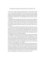
Figure 4.1(A) refers to the starting TiO
2
materials. After 6-10 hrs of 10M NaOH
hydrothermal treatment at 120
o
C (Figure 4.1(B), 4.1(C), 4.1(D)), step-like structures
and nanosheets exfoliated from bulk TiO
2
were observed. This strongly suggests that
a sheet-folding process is involved. Curling and scrolling of the nano sheets can be
observed in Figure 4.1(E) and Figure 4.1(F) (18hr). In Figure 4.1(I) and Figure
4.1(J) (24hr) of the hydrothermal process, formation of TiO
2
-derived nanotubes is
observable. Figure 4.1(K) and Figure 4.1(L) show the multi-layered nanotubular
structure after TiO
2
-derived nanotubes were washed with 0.1M HCl.
101
D
A
C
B
F
E
102
Figure 4.1 (A-L) TEM Observation of sodium titanate nanotube Formation.
H
G
I
L
J
K
103
4.1(A): Starting material, commercial TiO
2
sample.
4.1(B): Commercial TiO
2
after 10 hours of 10 M NaOH hydrothermal processing at 120
o
C.
4.1(C): Layered structure around TiO
2
after 10 hours of 10 M NaOH hydrothermal processing at 120
o
C.
4.1(D): TiO
2
after 10 hours of 10M NaOH hydrothermal processing at 120
o
C layered structure peel off from the
surface.
4.1(E): TiO
2
after 18 hours in 10 M Na10 hours of 10 M NaOH hydrothermal process at 120
o
C, curving formed.
4.1(F): TiO
2
after 18 hours of 10 M NaOH hydrothermal processing at 120
o
C.
4.1(G): TiO
2
after 20 hours 10 hours of 10 M NaOH hydrothermal processing at 120
o
C, end of tube.
4.1(H): TiO
2
after 20 hours of 10 M NaOH hydrothermal processing at 120
o
C.
4.1(I): TiO
2
after 24 hours of 10 M NaOH hydrothermal processing at 120
o
C.
4.1(J): TiO
2
after 24 hours of 10 M NaOH hydrothermal processing at 120
o
C.
4.1(K): TiO
2
after 48 hours of 10 M NaOH hydrothermal processing at 120
o
C.
4.1(L): TiO
2
after 48 hours of 10 M NaOH hydrothermal processing at 120
o
C.
4.2.2 Preparation of Au/TiO
2
via Colloids-Impregnation Procedure
Commercial TiO
2
(Merck, anatase), TiO
2
nanotubes, and four other TiO
2
supports
from ISHIHARA SANGYO KAISHA, LTD are labeled as CB, NT, MC-50, TTO-D-
1, TTO-S-1 and MC-150 respectively. These six kinds of titanium oxide were then
used as support for the preparation of TiO
2
supported gold nano particle samples
using colloids-based method. HAuCl
4
(1mM) is used as a precursor, NaBH
4
(0.1M) as
a reducing agent and lysine as a capping agent. During the reduction period,
sonication was applied. The slurry was dried at 70ºC after centrifuged for four times
using DI water.
20-24
4.2.3 Evaluation of Catalytic Activity
Catalytic runs were carried out at atmospheric pressure in a continuous-flow fixed-
bed quartz micro-reactor (I.D. 4 mm) packed with samples and quartz wool. Before
testing, the catalysts were pre-treated in situ with a flow of air (100 ml/min) for 1 h at
200 or 300
o
C. For CO oxidation reactions, the feed gas was a mixture of 90%He +
5%CO + 5%O
2
, introduced at a gas hourly space velocity (GHSV) of 60,000 cm
3
g
-1
h
-
1
. For preferential oxidation of CO in the presence of hydrogen, the feed gas was a
70%H
2
+ 1%CO + 2%O
2
mixture, introduced into the reactor at a GHSV of 60,000
104
cm
3
g
-1
h
-1
. For both reactions, the reaction products were analyzed on-line using
Shimadzu GC-2010 gas chromatography equipped with a thermal conductivity
detector (TCD). The catalysts were evaluated for activity (in terms of CO conversion
and CO
2
productivity) in a temperature range of 20-300
o
C. Data were collected after
the system had stabilized for at least 15mins at every set reaction temperature. The
Conversion and Selectivity are calculated in terms of concentration:
CO conversion (%) =
Inlet CO concentration – Outlet CO concentration
x 100%
Inlet CO concentration
O
2
selectivity (%) =
Inlet CO concentration – Outlet CO concentration
x 100%
2 x (Inlet O
2
concentration – Outlet O
2
concentration)
For kinetics study, the catalyst was diluted with SiC powder. Absolute mass-specific
reaction rates were calculated using Eq. (4.1). Detail calculation of CO Conversion,
Selectivity and Kinetic data can refer to Chapter 3 (3.2.2 )
r
CO
=
ċ
CO,in
X
CO
V
gas
[moles·s
-1
g
cat
-1
] Eq. (4.1)
m
cat
4.2.4 Characterization of catalysts
Powder X-ray diffraction patterns were recorded at room temperature on a Bruker D8
Advance Diffractometer using a Cu Kα radiation source. Diffraction angles were
measured at a step rate of 0.015
o
/s in the range of 10-80
o
(2θ). Transmission electron
microscope measurements were performed on a Tecnai TF 20 S-twin instrument with
105
a Lorentz lens. Before measurement, all samples were ultrasonically dispersed in
ethanol solvent and then dried over a carbon grid. The average size of the Au particles
and its distributions were estimated by counting about 300 Au particles. The Au and
Ti contents of prepared catalysts were determined by X-ray fluorescence multi-
elemental analyses on a Bruker AXS S4 Explorer. The in-situ Diffusion Reflectance
Infrared Fourier Transform spectroscopy of CO adsorption study was carried out on a
Bio Rad FTIR 3000 MX spectrometer equipped with a reaction cell (modified
Harricks model HV-DR2). The Au/TiO
2
catalyst was loaded into the DRIFT cell with
1:1 weight ratio with KBr. The spectra were acquired with a resolution of 4cm
-1
typically averaging 150 scans. The sample was purged using helium flow (20 ml/min)
for 2 hrs before exposure to the reaction gas. For CO adsorption experiments, 2.0%
CO were used to investigate the relative surface reaction rate. And as for DRIFT
study on surface species during CO oxidation reaction, 2%CO + 2%O
2
(He as balance
gas) were used as the reactant gas. The detailed experimental procedure implemented
for CO adsorption and CO oxidation DRIFT study is presented in Table 4.1.
Table 4.1 Experimental procedure for CO adsorption and oxidation DRIFT study
CO adsorption
CO oxidation
Pre-treat catalyst in air (He) flow at 300
o
C (573 K) for 1 hour and then cool down
to RT under He flow
Pre-treat catalyst in air (He) flow at 300
o
C (573 K) for 1 hour and then cool down
to RT under He flow
Background spectra: Catalyst in He
Background spectra: Catalyst in He
0.1% CO (10 min)
0.1% CO+O
2
(10 min)
106
Purge in He flow for at least 30 mins
remove gas phase CO and physisorbed
CO
Purge in He flow for at least 30 mins
remove gas phase CO and physisorbed
CO
Take spectra of 0.1%CO adsorption
Take spectra of 0.1%CO oxidation
Purge in He flow for 1hour
Purge in He flow 1 hour
0.2% CO (10 min)
0.2% CO+O
2
(10 min)
Purge in He flow for at least 30 mins
remove gas phase CO and physisorbed
CO
Purge in He flow for at least 30 mins
remove gas phase CO and physisorbed
CO
Take spectra of 0.2%CO adsorption
Take spectra of 0.2%CO oxidation
Purge in He flow for 1hour
Purge in He flow for 1hour
2% CO (10 min)
2% CO+O
2
(10 min)
Purge in He flow for at least 30 mins
remove gas phase CO and physisorbed
CO
Purge in He flow for at least 30 mins
remove gas phase CO and physisorbed
CO
Take spectra of 2%CO adsorption
Take spectra o 2% oxidation
X-ray photoelectron spectroscopy was performed on a VG ESCALAB XPS, ESCA
MK II using Mg Kα (1254.6eV) source under UHV better than 3 × 10
-9
torr. The
background contribution B (E) (obtained by the Shirley method) caused by inelastic
processes was subtracted, while the curve-fitting was performed with a Gaussian-
Lorentzian profile, and binding energies (BEs) were calculated using the Origin 7.0
107
software.
The in-situ XPS experiments were performed in a UHV chamber at the SINS
beamline of the Singapore synchrotron light source (SSLS) at National University of
Singapore.
25
XPS spectra were measured by a hemispherical electron energy analyzer
(EA 125, Omicron NanoTechnology GmbH). The XPS experiments were done at
normal emission, and the photon energy resolution for the experiments was set to
about 0.5 eV. XPS measurements were done at constant pass energy mode with
overall energy resolution. The experimental procedure implemented for CO
adsorption and oxidation in-situ XPS study are summarized in Table 4.2
Table 4.2 Experimental procedure for CO adsorption and oxidation in-situ XPS study
CO adsorption
CO oxidation
As-prepared catalyst in pretreatment chamber,
degas for 30 min then transfer to analysis chamber
As-prepared catalyst in pretreatment chamber,
degas for 30 min then transfer to analysis chamber
Wide Scan
Wide Scan
Scan for C1s, O1s, Ti 2p and Au 4f
Scan for C1s, O1s, Ti 2p and Au 4f
Transfer the samples back to pre-treatment
chamber and 2% CO in He does was injected into
pretreatment chamber with the chamber pressure
at 1*10
-4
Torr for 10min
Transfer the samples back to pre-treatment
chamber and 2% CO + 2% O
2
in He does was
injected into pretreatment chamber with the
chamber pressure at 1*10
-4
Torr for 10min
CO does was pumped out and sample was outgas
for 1hour then transferred back to analysis
chamber
CO + O
2
does was pumped out and sample was
outgas for 1hour then transferred back to analysis
chamber
Scan for C1s, O1s, Ti 2p and Au 4f
Scan for C1s, O1s, Ti 2p and Au 4f
4.3 Results and Discussions
4.3.1 Characterization of catalysts
108
Figure 4.2 shows the TEM micrographs of the six Au/TiO
2
samples after pre-
treatment at 300
o
C in air for 1 hour. The morphology of the oxide supports does not
change after the gold deposition.
Figure 4.2 (A-F) TEM micrograph of six Au/TiO
2
samples pre-treated in air for 1 hour at 300
o
C
A: Au/MC-150 ( Anatase, 286.9m
2
/g) ; B: Au/MC-50 ( Anatase, 210.4m
2
/g)
C: Au/TTO-S1( Rutile 99.4m
2
/g); D: Au/TTO-D1( Rutile 117.3m
2
/g )
E : Au/TiO
2
(NT) (Anatase 287m
2
/g ); F : Au/TiO
2
(CB) Anatase 57m
2
/g)
A
B
E
F
D
C
109
Figure 4.3 shows the size distribution of the Au nanoparticles in the six Au/TiO
2
samples after pre-treated at 300
o
C in air for 1 hour. Detailed information for XRF and
BET results of TiO
2
supported gold samples are shown in Table 4.3.
Figure 4.3 Bar graph of six kinds of Au/TiO
2
samples
a: Au/TiO
2
(CB) b: Au/TiO
2
-TTO-S1 c: Au/TiO
2
-TTO-D1
d:Au/TiO
2
-MC50 e: Au/TiO
2
-MC150 f: Au/TiO
2
(NT)
Table 4.3 Au wt% in six kinds of Au/TiO
2
samples from XRF and their BET results
Au/MC-150
Au/MC-50
Au/TTO-S1
Au/TTO-D1
Au/TiO
2
(NT)
Au/TiO
2
(CB)
XRF
(Au wt %)
As
prepared
1.9
2.0
2.6
2.3
1.8
2.1
BET
m
2
/g
As
prepared
285.9
210.4
99.4
117.3
287
41
Pre-treated
at 200
o
C
279.4
192.5
90
106
271
39
Pre-treated
at 300
o
C
264.2
189.8
87.3
104
263
37
110
The gold loadings of these Au/TiO
2
samples were between 1.06 and 0.73% according
to the x-ray fluorescence (XRF) results. It is noticed that the six samples have
different BET surface area, decreasing in the order: Au/M-150 ~ Au/TiO
2
(NT) >
Au/MC-50 > Au/TTO-D1 > Au/TTO-S1 > Au/TiO
2
(CB) and there are not many
differences for the surface area of samples before and after being pre-treated.
Figure 4.4 is the XRD patterns of the six TiO
2
supports. There are two kinds of TiO
2
structures with the six Au/TiO
2
samples. The TiO
2
in Au/MC-50, Au/MC-150,
Au/TiO
2
CB and Au/TiO
2
NT exist in anatase phase, while the TiO
2
in Au/TiO
2
-TTO-
S1 and Au/TiO
2
-TTO-D1 in rutile phase. Note that the (110) diffraction at 25
o
is
rather weak in TiO
2
(NT) compared to other bulk TiO
2
samples.
20 40 60 80
Intensity(a.u.)
2
TiO
2
(NT)
TiO
2
(CB)
MC-50
MC-150
TTO-D-1
TTO-S-1
Figure 4.4 XRD patterns of six différent TiO2 supports: TTO-D1, TTO-S1, MC-50, MC 150,
TiO
2
(CB) and TiO
2
(NT).
4.3.2 Catalytic Activity for CO Oxidation Reaction over the NanoGold Supported
on Various TiO
2.
111
Before the reaction, all six samples were purple-pink color powder, and no changes in
color after the reactions were observed. Also, no obvious changes for the Au
nanoparticles were found in the TEM micrographs of these samples before and after
the CO oxidation reaction. The CO oxidation on the six TiO
2
samples without Au
deposition were also conducted, showing almost no catalytic activities for CO
oxidation at temperatures lower than 200
o
C when the GHSV value was set at 60,000
cm
3
g
-1
h
-1
.
Figure 4.5 shows the CO conversion over the six catalysts: Au/TiO
2
-TTO-S1,
Au/TiO
2
-TTO-D1 Au/MC-50, Au/MC-150, Au/TiO
2
(CB) and Au/TiO
2
(NT) after
being pretreated in air for 1 hour at 200
o
C, as a function of the reaction temperature.
Figure 4.5 Conversion of CO as a function of reaction temperature over six TiO
2
samples pre-
treated at 200
o
C. Reaction conditions: 5%CO+5%O
2
in He, GHSV: 60,000 cm
3
g
-1
h
-1
.
Among the 6 catalysts, Au/TiO
2
(NT) is the best catalyst, which converted 100% CO
to CO
2
at 40
o
C. Note that the six samples have similar Au loading and particle size
distribution but different BET surface area. The activity of the catalysts changed in
20 40 60 80 100 120 140
0
20
40
60
80
100
CO conversion(%)
Temp(
o
C)
Au/TiO
2
CB
Au/TiO
2
-TTO-S-1
Au+TiO
2
-TTO-D1
Au+TiO
2
-MC-50
Au+ TiO
2
-MC-150
Au+TiO
2
(NT)
112
the same order of surface area: Au/MC(150) (279m
2
/g) > Au/MC(50) (192m
2
/g)>
Au/TTO(D1) (106m
2
/g)> Au/TTO-S1 (90m
2
/g) > Au/CB (39m
2
/g). Actually the CO
oxidation activity on Au/TTO-S1 and Au/TTO-D1, in which the supports have rutile
structure, was basically the same as that on anatase Au/MC-50, indicating that the
support crystalline structure does not affect the Au catalysis significantly in this
example, disagreed with some reports in literature.
28
Au/TiO
2
(NT) is obviously better
than Au/MC150, though both of them have very similar BET surface area, and are in
the anatase form. TiO
2
nanotubes are derived from commercial TiO
2
(CB), but their
activities as the support of Au catalysts are remarkably different (100% conversion at
40
o
C vs 120
o
C). All these will be further investigated in the sections below.
The influence of the gas hourly space velocity over the catalytic performance of
Au/TiO
2
(CB) sample is illustrated in Figure 4.6
Figure 4.6 Conversion of CO as a function of reaction temperature over Au/TiO
2
(CB)
samples at different input gas flow rate. Sample pre-treated at 200
o
C. Reaction conditions:
5%CO+5%O
2
in He, GHSV: 60,000 cm
3
g
-1
h
-1
0 50 100 150 200 250
0
20
40
60
80
100
CO conversion(%)
Temp(
o
C)
30mlmin
-1
50mlmin
-1
80mlmin
-1
100mlmin
-1
120mlmin
-1
113
As stated by BL Zhu, the pre-treatment temperature can also affect the catalytic
activity of gold supported samples.
26
In order to study the effect of pre-treatment
temperature on Au/TiO
2
samples’ for CO oxidation (reaction gas: 5%CO + 5%O
2
in
He) catalytic activity, Au/TiO
2
(CB) and Au/TiO
2
(NT) were pre-treated in air for 1
hour at 200, 300 and 400
o
C respectively. Figure 4.7 show CO oxidation activities
over the Au/TiO
2
(CB) and Au/TiO
2
(NT) samples pre-treated at 200, 300 and 400
o
C
respectively. Both these two samples showed the same catalytic activity trend
according to pretreatment condition, i.e. A
300
o
C
>A
200
o
C
(A=activity). The samples that
were calcined at 300
o
C are better catalysts for CO oxidation than the samples that
were pre-treated at 200.
Figure 4.7 Conversion of CO as a function of reaction temperature over Au/TiO
2
(CB) and
Au/TiO
2
(NT) samples pre-treated at different temperature; Reaction conditions:
5%CO+5%O
2
in He, GHSV: 60,000 cm
3
g
-1
h
-1
20 40 60 80 100 120 140 160
0
20
40
60
80
100
CO conversion(%)
Temp(
o
C)
Au/TiO
2
CB 200
o
C pretreat in air 1hour
Au/TiO
2
CB 300
o
C pretreat in air 1hour
Au/TiO2 NT 200
o
C pretreat in air 1hour
Au/TiO2 NT 300
o
C pretreat in air 1hour
114
Kinetics of CO Oxidation.
Table 4.4 lists the kinetic data of the Au/TiO
2
catalysts for the CO oxidation
(5%CO+5%O
2
in He) at temperatures from 25 to 70
o
C. All the samples were pre-
treated in air for 1 hour at 300
o
C. The activation energy of our samples is compatible
to other Au/TiO
2
catalysts reported in literature.
27
In particular Au/TiO
2
(NT) and
Au/MC-150 are the most active catalysts. On the basis of this study, it is inferred that
surface modification of TiO
2
support may dramatically influence the catalytic activity
of Au nanoparticles.
Table 4.4 comparision of published literature data for CO oxidaion rates on metal oxide supported Au
catalysts.
Catalyst
particle size (nm)
preparation
a
temp. (K)
Ea (kJ/ mol)
r
CO
b
ref
[mol/g
cat
s
]
[TOF s
-1
]
Au (2.1wt %)/TiO
2
(CB)
Au (1.8wt %)/TiO
2
(NT)
Au(2.6wt%) TiO
2
TTO-S1
Au(2.3wt%) TiO
2
TTO-D1
Au(2.0wt%) TiO
2
MC-50
Au(1.9wt%) TiO
2
MC-150
Au (0.5wt %)/ -TiO
2
Au (0.8wt %)/ -TiO
2
Au (1.8wt %)/ -TiO
2
Au (2.3wt %)/ -TiO
2
Au (3.1wt %)/ -TiO
2
3.9
4.1
3.8
3.9
4.0
4.1
3.5
3.1
2.7
2.5
2.9
CB
CB
CB
CB
CB
CB
DP
DP
DP
DP
DP
300
300
300
300
300
300
300
300
300
300
300
23
16
28
27
18
17
27
19
18
20
27
3.6 x 10
-7
6.2 x 10
-6
3.7 x 10
-7
7.4x 10
-7
4.8 x 10
-6
5.6 x 10
-6
3.8 x 10
-7
6.9 x 10
-7
5.5 x 10
-6
4.5 x 10
-6
2 x 10
-5
1.6 x 10
-2
1.3x 10
-1
3.6x 10
-2
3.5x 10
-2
1.0 x 10
-1
1.1x 10
-1
3.7 x 10
-2
3.4x 10
-2
1.2 x 10
-1
6.8x 10
-2
2 .6x 10
-1
this study
this study
this study
this study
this study
this study
27
27
27
27
27
a
Preparation methods: CB collide based method; DP, deposition participation;
Preferential Oxidation of Carbon Monoxide in the Presence of Hhydrogen (PROX)
Figure 4.9 and Figure 4.10 show the CO conversion and the O
2
selectivity as a
function of reaction temperature over the Au/TiO
2
(NT) and Au/TiO
2
(CB) samples in
the PROX reaction. Experiments were conducted under flow of 1%CO + 2%O
2
+
115
70%H
2
balanced with helium at a GHSV of 6,000 cm
3
g
-1
h
-1
. The samples were pre-
treated at 300
o
C in air for 1 hour. The Au/TiO
2
(NT) sample shows better CO
conversion than Au/TiO
2
(CB), but there is not much difference for these two samples
in terms of O
2
selectivity.
20 30 40 50 60
0
20
40
60
80
100
CO conversion
(
%
)
Temperature(
o
C)
CO conversion(%)
Selectivity of O
2
(%)
Au/TiO
2
(NT)
32
36
40
44
48
52
56
60
64
68
72
76
Figure 4.9 CO conversion and O
2
selectivity as a function of reaction temperature over Au/TiO
2
(NT) samples. Reaction conditions: 1%CO+2%O
2
+70%H
2
in He, GHSV: 6,000 cm
3
g
-1
h
-1
.
Sample pre-treated at 300
o
C in air for 1 hour
116
15 30 45 60 75
0
20
40
60
80
CO conversion(%)
Selectivity of O
2
(%)
CO conversion
(
%
)
Temp(
o
C)
Au/TiO
2
(CB)
36
40
44
48
52
56
60
64
68
72
Selectivity
(%)
Figure 4.10 CO conversion and O
2
selectivity as a function of reaction temperature over Au/TiO
2
(CB) samples. Reaction conditions: 1%CO+2%O
2
+70%H
2
in He, GHSV: 6,000 cm
3
g
-1
h
-1
.
Sample pre-treated at 300
o
C in air for 1 hour.
4.3.3 DRIFTs Study on CO Adsorption and CO Oxidation over Gold Supported
on TiO
2
Catalysts
DRIFTS study on CO adsorption and CO oxidation over the supported gold catalysts
were conducted, following the procedure listed in Table 4-1. Only parts of the results
are shown here for convenience of analysis and brevity.
Figure 4.11 shows the DRIFT spectra recorded in the region of 2050-2250 cm
-1
over
the Au/TiO
2
(CB) catalyst at room temperature after exposed to a flow of CO (0.1%
or 0.2% or 2% in sequence) for 10 minutes, followed by helium purging for at least 30
min. The catalyst was pre-treated in air flow (20mlmin
-1
, 14.7 psi) for 1 hour at
300
o
C, then cooled down to room temperature. Five minutes after the introduction of
117
CO, a sharp band was seen at 2102 cm
-1
, which has been assigned to CO adsorbed on
Au. Bands were also seen in the 1700-1000 cm
-1
region. Five minutes after stopping
CO, the main adsorbed CO peak at 2105 cm
-1
was reduced in intensity as CO desorbs
from the surface, with an accompanying shift to a higher wavenumber of 2108 cm
-1
at
low CO concentration (0.1% and 0.2% CO) Similar phenomenon (i.e. the shifter of
CO adsorption peak to higher wavemnumber) was observed as CO concentration was
increased (2% CO), except that the peak at 2102 cm
-1
shifted to 2106 cm
-1
. The band
at this range was universally assigned to a carbon monoxide molecule linearly
adsorbed on top of a single gold atom.
28-29
From our results, we can tell that with
increased CO partial pressure, the Au
0
—CO band shifted to lower frequency. Figure
4.11 (d) shows the DRIFT spectra recorded after soaking in the same sample in a flow
of 2%CO + 2%O
2
for 10 minutes, followed by helium purge for at least 30 minutes
before the measurements. The DRIFT spectra of Au/TiO
2
(CB) sample after CO
adsorption (Figure 4.11 (c)) and CO+O
2
adsorption (Figure 4.11(d)) are of great
similarity except that Au/TiO
2
(CB) sample after CO oxidation had greater bands
intensity in this range. This result confirmed the assumption of non-competitive
adsorption, i.e. the adsorption of carbon monoxide was not affected by the presence of
oxygen. Though it is rather weak the IR band at 2141 cm
-1
appears in the 4 spectra,
and may be due to CO molecules adsorbed at Au
+
. A few more weak bands between
2210 and 2150 cm
-1
after the introduction of CO + O
2
may be assigned to CO-(O
2
-
)Au
3+
and CO—(HO)Ti
4+
, i.e. the vibration of CO bonded on Ti
4+
ions site.
30-34
Two
kinds of cations can be detected on anatase surface by CO adsorption at room
temperature: α sites and β sites were used to denote the more strongly bonding sites
and more weakly bonding sites individually. CO adsorption on α sites leads to a band
at a higher wavenumber. And it is assumed that α sites are four-coordinated Ti
4+
ions
118
(with two coordination vacancies). A surface concentration of about 0.1-0.3 Ti
4+
nm
-2
,
was also reported.
29-31
CO adsorbed at room temperature on more weakly bonding (β)
sites Ti
4+
(anatase) gives rise to a lower wave-number band.
32-38
The β sites are
proposed to be five-coordinated titanium ions
39-42
with a density of 0.5 to 1.0 Ti
4+
nm
-2
. It is noted that all the CO-bands can be easily removed by He purging, easier
on Au/TiO
2
(NT) than on Au/TiO
2
(CB). In the i.r. spectrum the very strong broad
band in the range between 3200 and 3600 cm
-1
is attributed to hydrogen-bonded OH
or H
2
O. (Figure 4.12) It is worthy to note that the intensity of OH group for
Au/TiO
2
(CB) or Au/MC150 is weaker than that of Au/TiO
2
(NT) after normalization
with respect to the Ti-O band. Compared to the Ti
4+
–OH at 3687 cm
-1
, the broad band
around 3300 cm
-1
is significantly stronger, indicating the existence of large amount
hydrogen bonded OH or H
2
O, and they are stronger on TiO
2
(NT) than other samples.
This is understandable since titania nanotubes are prepared via a thermal wet chemical
process as will be discussed in the subsequent sections.
119
Figure 4.11 DRIFT spectra recorded in the region of 2050-2250 cm
-1
over the Au/TiO
2
(CB)
catalyst at 298 K after soaking into a flow of CO or CO + O
2
for 10 mins, followed by helium
purge for 30 min. (a) 0.1% CO (helium balance) (b) 0.5% CO (helium balance) (c) 2% CO
( helium balance) (d) 2% CO+ 2%O
2
( Helium balance) . Before the measurements, the catalyst
was pre-treated in air flow (20 ml min
-1
, 14.7 psi) for 1 hour at 300
o
C, then cooled down to room
temperature.
120
4000 3500 3000 2500 2000 1500 1000 500
0
5
10
15
20
25
Intensity(a.u.)
Wavenumber(cm
-1
)
Au/TiO
2
NT
Au/TiO
2
MC150
Au/TiO
2
CB
Figure 4.12(A) DRIFT spectra over the Au/TiO
2
(NT), Au/TiO
2
MC-150, and Au/TiO
2
(CB).
catalyst at 298 K after soaking into a flow of pure helium for 30 mins. Before the measurements,
the catalyst was pre-treated in air flow (20 ml min
-1
, 14.7 psi) for 1 hour at 300
o
C, then cooled
down to room temperature. The spectra are normalized with respect to the Ti-O bands between
750 and 1100 cm
-1
.
(A)
121
Figure 4.12(B) DRIFT spectra over the Au/TiO
2
(NT) sample taken under different treatments: (a)
after soaking in 2% CO + 2% O
2
reactant gas for 10 minutes at 25
o
C; and (b) after soaking in 2%
CO gas for 10 minutes at 25
o
C; (c) after purge in helium flow Before the measurements, the
catalyst was pre-treated in air flow (20 ml min
-1
, 14.7 psi) for 1 hour at 300
o
C, then cooled down
to room temperature. After gas adsorption it was purged by helium for 30 min. The spectra
are normalized with respect to the Ti-O bands between 750 and 1100 cm
-1
.
Figure 4.12(B) shows the DRIFT spectra over the Au/TiO
2
(NT) catalysts at 25
o
C
after soaking in 2% CO and 2% CO + 2% O
2
reactant gas for 10 minutes. Line (a) of
the spectra is taken after soaking in 2% CO for 10 minutes followed by helium purge
for 30 minutes. Line (b) of the spectra is taken after soaking in 2% CO + 2% O
2
reactant gas for 10 minutes, followed by helium purge for 30 minutes. Before the
measurements were taken, the catalyst was pre-treated in air flow (20 ml min
-1
, 14.7
psi) for 1 hour at 300
o
C, then cooled down to room temperature. CO adsorption did
not change the OH band of the Au/TiO
2
catalysts. However the CO+O
2
adsorption
4000 3500 3000 2500 2000 1500 1000 500
3800 3700 3600 3500 3400 3300 3200 3100 3000
a
b
c
Intensity(a.u.)
Wavenumber(cm
-1
)
B