High resolution x ray diffraction study of phase and domain structures and thermally induced phase transformations in PZN (4 5 9)%PT 3
Bạn đang xem bản rút gọn của tài liệu. Xem và tải ngay bản đầy đủ của tài liệu tại đây (4.19 MB, 7 trang )
71
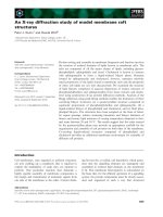
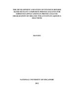
Figure 5.10 (002) RSM taken from the as-polished surface of annealed
PZN-4.5%PT, showing the smeared contour lines over the area in
the lower 2θ sides of the main (002)
R
peak despite after annealing
at 600 °C for 5 h. The intensity contours are on log scale.
72
(a) PZN-7%PT
As
-
polished surface
(b) PZN-7%PT
Fractured s
urface
(e) PZN-9%PT
A
s
-
polished surface
(f) PZN-9%PT
Fractured
surface
(c) PZN-8%PT
As
-
polished surface
(d) PZN-8%PT
Fractured
surface
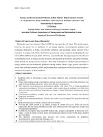
Figure 5.11 (a), (c) and (e) (002) RSMs taken from the as-polished surface of
PZN-7%PT, PZN-8%PT and PZN-9%PT after annealing at 257
°C for 1 h, respectively. (b), (d) and (f) same as (a), (c) and (e)
but taken from the fractured surface. The intensity contours are
on log scale.
73
The smeared contour lines over an area of the ω-2θ plane at the lower 2θ side of the
main (002)
R
peak in the (002) RSM (Figure 5.10) indicates that the diffraction effects
associated with the polishing processes down to 1 µm remain despite annealing to high
temperature.
The HR-XRD (002) RSMs were also performed on polished-and-annealed (at
257 °C for 1 h) PZN-7%PT, PZN-8%PT, and PZN-9%PT single crystals. The results
are provided in Figures 5.11(a), (c), and (e). To expose the bulk material, the same
samples were later fractured into two halves and were again x-rayed. The results are
shown in Figures 5.11(b), (d), and (f).
The polished-and-annealed bulk PZN-PT single crystals were found to cover
with a deformed layer even after heating to above T
C
, giving rise to smear effect in the
x-ray diffraction patterns (Figures 5.11a, c, and e). As a result, the polished surface can
hardly reveal any useful structural information of the crystals hence unsuitable for
x-ray diffraction studies.
It should be emphasized that distinct diffraction peaks were obtained from the
fractured surface (Figures 5.11b, d, and f), suggesting that the fractured surface are
relatively strain-free bulk structure which are more suitable for x-ray diffraction study.
5.3.2 Electrical resistance
74
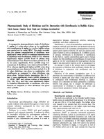
The effect of room-temperature poling on the stability of the deformed
surface layer was also investigated. Figure 5.12 shows the XRD profiles when a dc
E-field of increasing strength was applied to the as-polished sample. This figure shows
that the lower 2θ peak is no longer present after the poling field was increased to 1.5
kV/mm. Thus, an appropriate poling can eliminate most of the deformed surface layer.
However, such a poling treatment should be carried out with care to avoid a non-R
phase or overpoling phenomenon as a result of E-field induced phase transformation in
relaxor single crystals [1, 16, 90, 91].
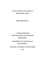
A different result was obtained when poling was applied on annealed samples
instead. As shown in Figure 5.13, the lower 2θ peak persisted in the annealed samples
even after poling to high fields (up to 1.5 kV/mm). The annealing treatment thus helps
stabilize the deformed surface layer such that it becomes more resistant to the poling
treatment.
5.4 Summary of main observations
(a) The cause for the occurrence of the extremely broad lower 2θ peak adjacent to
the main (002)
R
peak in standard XRD profiles of (001)-orientated PZN-PT
single crystals has been examined. This diffraction arises from a surface layer
produced by mechanical polishing during the sample preparation stage.
75
Figure 5.12 Effect of increasing poling field on the lower 2θ peak for
as-polished samples without any prior annealing. Note that the
lower 2θ peak is largely eliminated after poling to 1.5 kV/mm.
Sample thickness is 1mm.
Intensity (arb. units)
2θ
42 43 44 45
(a) 0.2 kV/mm
(b) 0.7 kV/mm
(c) 1.5 kV/mm
<002>
R
<002>
R
<002>
R
76
Figure 5.13 Same as Figure 5.12 but for sample annealed at 600 °C for 1 h
prior poling treatment. Note the persistence of the lower 2θ peak
after poling to 1.5 kV/mm at room condition. Sample thickness
is 1mm.
Intensity (arb. units)
2θ
42 43 44 45
(a) 0.2 kV/mm
(b) 0.7 kV/mm
(c) 1.5 kV/mm
<002>
R
<002>
R
<002>
R
77
(b) High-resolution synchrotron RSMs revealed that this surface layer consisted of
highly distorted R phase owing to the soft elastic constants of R. The distorted R
phases are microscopic in size, of a wide range of lattice parameters and are
stressed in intense compression in the plane of the polished surface.
(c) Under the PLM, the surface layer may exhibit parallel domain patterns when the
polishing was performed in a given direction but was relatively featureless
except regions of slight birefringence when the polishing direction was
uncoordinated.
(d) This polishing-induced surface layer was fairly resistant to annealing but could
be largely eliminated by poling to 0.7-1.5 kV/mm at room temperature. After
annealing, it became resistant to poling such that the lower 2θ peak persisted
even after poling at 1.5 kV/mm.
(e) The present work showed that the diffractions arose from polished surface
pertained to surface phase while those from the fractured surface represented the
bulk phase. The fractured surfaces are relatively strain-free surface which are
suitable for x-ray diffraction study of bulk structure in relaxor ferroelectric
single crystals.