High resolution x ray diffraction study of phase and domain structures and thermally induced phase transformations in PZN (4 5 9)%PT 8
Bạn đang xem bản rút gọn của tài liệu. Xem và tải ngay bản đầy đủ của tài liệu tại đây (9.33 MB, 16 trang )
141
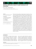
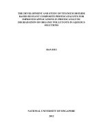
Figure 8.8 Room temperature HR-XRD (002) RSM of an as-grown (unpoled)
PZN-6%PT. Peaks d
3
, d
4
and d
5
are R* diffractions, while peaks d
1
and
d
2
are the (100)
T
diffraction and (001)
T
microtwin diffractions,
respectively (see text for details).
142
of (001)
T
twin diffractions in as-grown PZN-6%PT single crystal may be due to the
higher residual stress and/or the presence of a much higher portion of T nanotwin
domains in this crystal sample, or a combination of both factors.
8.4 Thermally-induced phase transformations in unpoled PZN-8%PT
8.4.1 Temperature dependent polarization characteristics
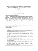
Figure 8.9(a) shows the temperature-dependent ε’ at various frequencies (0.1
kHz – 1 MHz) of an unpoled (annealed) PZN-8%PT sample during the ZFH. The ε’
increased gradually with temperature initially, followed by a weak anomaly over the
temperature range of about 90-105 °C. This anomaly can be more readily seen in the
1/ε’ versus temperature plot. As shown in the inset of Figure 8.9(a), the value of 1/ε’
showed a steeper drop at about 90 °C. In addition, a clear anomaly in ε’ (and a step-
like decrease in 1/ε’) was observed over the temperature range of 160-173 °C. The
latter anomaly was followed by a frequency dependent ε’ maximum (at T
max
), which
may be attributed to the dynamic relaxation processes of polar nanoclusters in the
material [95, 96].
Figure 8.9(b) shows the current signals of the unpoled PZN-8%PT single
crystal as a function of temperature. The unpoled sample displayed multiple but very
weak current signals over the temperature range of 90-113 °C. Of these activities, three
143
Temperature(
o
C)
40 60 80 100 120 140 160 180 200 220
J(mA/m
2
)
-0.010
-0.005
0.000
0.005
0.010
0.015
0.020
90 100 110
(b)
ε'(x10
4
)
0
2
4
6
(a)
(R*+T
σ
)
(R*+T
σ
+T)
T
R-T
T
C
(T*+C)
T
max
T
C
50 100 150 200
1/
ε
'(x10
-3
)
0.0
0.2
0.4
0.6
T
C
T
R-T
0.1 kHz
0.5
10
50
100
500
1 MHz
Figure 8.9 (a) ZFH ε’ and (b) ZFH J of unpoled (annealed) PZN-8%PT
crystal. The sample thickness is 1.5 mm.
144
more obvious current signals could be noted, at 97 ºC, 104 ºC, and 110 ºC, respectively
(see inset). There followed a period of no current activities on further heating until
about 165 ºC, at which a stronger current signal was detected, followed by a string of
weak current activities spreading over the temperature range of 165-170 ºC.
8.4.2 Structural studies
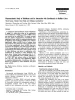
As described in Section 8.3, at 25 °C, the diffraction pattern of PZN-8%PT
contains four diffraction peaks, marked d
1
to d
4
in the Figure 8.10(a). These four
diffraction peaks are located at three different Bragg’s angles, i.e., d
1
and d
2
at 2θ ≈
44.95° (with ∆ω ≈ 0.54°), and d
3
and d
4
at 2θ ≈ 44.60° (∆ω ≈ 0.24°). The room
temperature structure of unpoled PZN-8%PT has been identified to be a (R+T
σ
) phase
mixture, in which the subscript
σ
denotes that the T phase is metastable stabilized by
the residual stress in the crystal.
Upon increasing the temperature to 80 °C, the (002) diffraction pattern
remained relatively unaffected. At 80 °C (Figure 8.10b), two new peaks superimposing
onto the existing diffraction peaks were noted, indicating the emergence of a new
phase. With increasing temperature, the peaks d
1
-d
4
gradually shifted towards the ω =
0° plane. At 95 °C (Figure 8.10c), only two peaks at 2θ ≈ 44.37° and 2θ ≈ 44.86°
remained. These two peaks are identified as the T phase since both peaks lie in the ω =
145
0° plane. It should be noted that the T phase that appeared at 95 °C is a stable T phase,
which is different from that of T
σ
at room temperature from thermodynamic point of
view. The stable T phase persisted above 95 °C which remained the only phase
detected up to 160 °C (Figures 8.10d-g).
Careful observation shows that the C phase, at 2θ ≈ 44.60º, started to emerge
at 160°C (Figure 8.10g). It is interesting to note from Figures 8.10(g)-(h) that the
emergence of the C phase caused the diffractions of the T phase to become
increasingly tilted out of the ω = 0° plane. The C phase, at 2θ ≈ 44.63º, remained the
dominant phase above 173 ºC (Figure 8.10i). The above-experiment was repeated with
several other unpoled PZN-8%PT single crystal samples. Similar results were obtained.
It is also interesting to note that a string of current signals was detected over
the temperature region of 90-113 °C (Figure 8.9b). As will be discussed in Chapter 9,
one likely cause could be the compositional segregation in the crystal, leading to a
range of R-T transformation temperature. Despite the thermal current signals, the
anomalies in the
ε
’ over the temperature range of 90-115 °C remained not obvious in
the unpoled sample. As discussed previously, this phenomenon was attributed to the
effect of the strong dynamic relaxation process of the polar nanoclusters in the material
which helps mask the anomalies in the ε’ displayed by the R-T transformation.
146
Figure 8.10 Temperature dependent (002) RSMs taken from fractured surface of
annealed PZN-8%PT crystal obtained at (a) 25 ºC, (b) 80 ºC, (c) 95 ºC,
(d) 120 ºC, (e) 140 ºC, (f) 150 ºC , (g) 160 ºC, (h) 165 ºC, and (i) 173 ºC.
The intensity contours are on log scale. The PZN-8%PT undergoes a
transformation of (R*+T
σ
)–(R*+T
σ
+T)–T–(T+T*+C) –C upon heating.
(a) 25
º
C: (R*+T
σ
)
(b) 80 ºC: (R*+T
σ
+T)
(c
) 95
º
C: T
(d) 120ºC: T
(e) 140ºC: T (f) 150ºC: T
(g) 160ºC: (T+T*+C) (h) 165ºC: (T*+C) (i) 173ºC: C
147
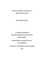
Figure 8.11 ZFH domain structures of annealed PZN-8%PT crystal observed by
the PLM at (a) 25 ºC, (b) 85 ºC, (c) 105 ºC, (d) 145 ºC, (e) 165 ºC,
and (f) 168 ºC. The sample thickness is about 100
µ
m. The PLM
observation is consistent with the HR-XRD results.
(a) 25 ºC
P/A= 45º
P/A= 0º
(c) 105 ºC
P/A= 45º
P/A= 0º (d) 145 ºC
P/A= 45º
P/A= 0º
(e) 165 ºC
P/A= 45º
P/A= 0º
[100]
[010]
200
µ
m
(b) 85 ºC
P/A= 45º
P/A= 0º
C
(f) 168 ºC
P/A= 45º
C
T
T
148
Figure 8.11 shows the domain structures obtained by the PLM as a function
of temperature. At 25 ºC, the crystal exhibited complete optical extinction at only P/A
= 45º (Figure 8.11a), indicating that the room temperature phase is the R phase. The R
phase remained till 85 ºC before the first sign of phase transformation (Figure 8.11b).
Gradual change in the extinction angle was observed above 85 ºC, suggesting that
some structural changes must have occurred. At 105 ºC, optical extinction was shown
to occur at P/A = 0
o
,
which may arise from the T phase (Figure 8.11c). The T phase
persisted upon increasing to higher temperature (Figures 8.11d-e). At 168 ºC, scattered
areas started to exhibit extinction at most P/A angles, suggesting the occurrence of the
C phase (Figure 8.11f). Above T
max
, the sample exhibited a total extinction, indicating
the C phase only. The PLM observation is thus consistent with the HR-XRD results
presented above.
8.5 Thermally-induced phase transformations in unpoled PZN-7%PT
8.5.1 Temperature dependent polarization characteristics
Figures 8.12(a) shows the temperature-dependent ε’ of the unpoled (annealed)
PZN-7%PT sample measured at various frequencies (0.1 kHz – 1 MHz). The ε’
increased gradually with temperature initially, followed by a step-up like anomaly near
90 °C. This anomaly can be more readily seen in the 1/ε’ versus temperature (see inset
149
Figure 8.12 (a) ZFH ε’ and (b) ZFH J of unpoled (annealed) PZN-7%PT
crystal. The sample thickness is 1.0 mm.
Temperature (
o
C)
40 60 80 100 120 140 160 180 200 220
J (mA/m
2
)
-0.004
-0.002
0.000
0.002
0.004
0.006
(b)
ε' (x10
4
)
0
2
4
6
8
T
C
T
max
T
R-T
C
T+T*
(T+T*+C)
(R*+T
σ
)
(R*+T
σ
+T*)
(a)
50 100 150 200
1/
ε
'(x10
-4
)
0.0
0.5
1.0
T
R-T
T
C
0.1 kHz
0.5
10
50
100
500
1 MHz
150
of Figure 8.12a). The ε’ remains relatively constant on further heating until about 160
°C. Over the temperature region of 160-165 °C, the second anomaly (and a sudden
plunged in 1/ε’) accompanied with a broad frequency dependent maximum was
observed at T
max
(i.e., temperature at ε’ maximum).
The temperature dependent current density obtained from the unpoled PZN-
7%PT single crystal is shown in Figure 8.12(b). There were hardly any current signals
until about 95 ºC where a string of current signals occurred in the region of 95-110 °C.
Of these current activities, a clear current response appeared at 110 °C. There followed
by a region where no major current activities were detected until at about 160 ºC, at
which a new string of strong current activities was detected over the temperature range
of 160-165 ºC.
8.5.2 Structural studies
Figure 8.13 shows typical (002) RSMs of the unpoled sample taken over the
temperature range of 25-175 °C. At 25 °C (Figure 8.12a), a broad convoluted R single
peak with 2θ ≈ 44.64° lying at ω = 0° plane was detected (see Section 7.2 for details).
Besides the main R peak, a weak peak located at 2θ ≈ 44.90° and lying out of the ω =
0° plane indicates that a small amount of the T phase may be present. The room
temperature structure of PZN-7%PT is thus a mixture of (R+T
σ
) in which the T
σ
is
151
metastable stabilized by the residual stress in the crystal.
With increasing temperature, the R phase remained as the stable phase with its
broadness gradually reduced in both the 2θ and ω planes. Figure 8.13(b) gives the (002)
mapping taken at 95 °C. It is interesting to note that the T
σ
at 2θ ≈ 44.80°-44.85°
persisted with the main R peak.
At 100 °C (Figure 8.13c), subtle changes in the diffraction pattern can be
noted, i.e., new diffractions at 2θ ≈ 44.40°-44.45° and 2θ ≈ 44.80° emerged. At 105 °C,
in addition to the existing (R+T
σ
) mixture phase, five new peaks (i.e., d
1
, d
2
, d
5
, d
6,
and
d
7
) became evident (Figure 8.13d). These peaks lie in three Bragg’s positions, with
peaks d
1
, d
2
and d
3
lying at 2θ ≈ 44.80°, d
4
at 2θ ≈ 44.60°, and d
5
, d
6
and d
7
at 2θ ≈
44.46°. While peaks d
2
, d
4
and d
6
lie in the ω = 0° plane, the remaining peaks lie out of
the ω = 0° plane.
Upon increasing the temperature to 115 °C, six peaks were diffracted (Figure
8.13e). Of the six peaks, d
1
, d
2
, and d
3
lie at 2θ ≈ 44.80° and d
4
, d
5
, and d
6
lie at 2θ ≈
44.48°. Note that peaks d
1
and d
3
at this temperature are separated by a significantly
larger ∆
ω
(≈ 0.46°) values as opposed to peaks d
1
and d
3
at lower temperatures (with
∆ω ≈ 0.28°).
Upon heating to 155 °C, the six diffraction peaks persisted despite slight
changes in their 2θ positions, from the initial value of 2θ ≈ 44.80º to 2θ ≈ 44.75º for d
1
,
152
d
2
and d
3
, and from 2θ ≈ 44.45º to 2θ ≈ 44.53º for d
4
, d
5
and d
6
, with the off ω = 0°
peaks shifting towards the ω = 0° plane (Figures 8.13f-g). The C phase, at 2θ ≈ 44.67º
(ω = 0º), started to emerge at 160 ºC (Figure 8.13h) with further reduction of the
diffraction intensity of other remaining peaks. Above 165 ºC, the C phase, at 2θ ≈
44.67º, remained as the dominant phase (Figure 8.13i).
Based on the analysis given in Table 6.1, the various diffraction peaks at 115
ºC (Figure 8.13e) may be assigned as (a) M
B
(d
1
, d
3
, d
4
, and d
6
) + T (d
2
and d
5
), (b) M
C
(d
1
, d
2
, d
3
, d
4
, and d
6
) + T (d
2
and d
5
) or T* (d
1
, d
3
, d
4
, and d
6
) + T (d
2
and d
5
) (see
Section 6.2.3 for details). The following reason helps to rule out the presence of the M
C
phase. That is, typically a
pc
≠ b
pc
for the M
C
phase. This means that the a
pc
and b
pc
diffractions for the M
C
should not lie on the same Bragg’s angle and that the b
pc
diffraction is non-degenerated. These features are not borne out by the diffractions
shown in Figure 8.13(e). Furthermore, Figure 8.12 revealed only one anomaly in ε’
and one major thermal current signal in the range of 140-170 ºC concerned. Based on
these observations, we may conclude that the relevant diffraction peaks at 115 ºC are
those of the (T+T*) domains.
It should be mentioned that upon heating from 115 ºC to 155 ºC (Figures
8.13e-g), the various diffraction peaks are of asymmetrical degeneracy. This
observation may be understood from the strained state and the unbalanced population
153
of R* and T* domains formed in the material near the R-T transformation temperature
(T
R-T
).
Figure 8.14 shows the domain structures obtained by the PLM as a function of
temperature. At 25 ºC, the crystal exhibited complete optical extinction at only P/A =
45º (Figure 8.14a), confirming that the room temperature phase is the R phase. The R
phase remained till 100 ºC before the first sign of phase transformation (Figure 8.14b).
Gradual change in the extinction angle can be noticed to begin at 110 ºC (Figure 8.14c),
suggesting that some structural changes must have occurred. Above 125 ºC, scattered
areas exhibit extinction at P/A = 0
o
,
which may arise from the T phase (Figures 8.14d-
e). On heating to T
max
≅ 165 ºC, the scattered areas started to exhibit extinction at most
P/A angles, suggesting the occurrence of the C phase (Figure 8.14f). Above T
max
, the
sample exhibited a total extinction indicating the C phase only. The PLM observation
is thus consistent with the HR-XRD results presented above.
8.6 Summary of main observations
(a) In addition to the R diffractions, T* domains could also be detected in PZN-(6-
8)%PT single crystals at room condition. Our HR-XRD RSM results indicate
that the T phase is likely to be a metastable phase stabilized by the
transformation-cum-cooling stress in the crystal. This is manifested by the stress
154
Figure 8.13 Temperature dependent (002) RSMs taken from fractured surface of
annealed PZN-7%PT crystal obtained at (a) 25 ºC, (b) 95 ºC, (c) 100
ºC, (d) 105 ºC, (e) 115 ºC , (f) 140 ºC, (g) 155 ºC, (h) 160 ºC and (i)
168 ºC. The intensity contours are on log scale. The PZN-7%PT
undergoes an (R*+T
σ
)–(R*+T
σ
+T*)–(T+T*)–(T+T*+C)–C phase
transformation sequence upon heating.
M
C
(d
1
, d
2
, d
3
, d
4
, and d
6
) + T (d
2
and d
5
), or (c) T* (i.e., d
1
, d
3
, d
4
, and d
6
) + T (i.e., d
2
and d
5
). We may rule out possibilities (a) and (b) as transformations of the type M
B
-C
and M
C
-C are not permitted by the crystal transformation theory [42, 98, see also
(h) 160ºC: (T+T*+C) (g) 155ºC: (T+T*)
(i) 168ºC: C
(a) 25ºC: R*+T
σ
(b) 95ºC: R*+T
σ
(c) 100ºC: (R*+T
σ
+T*)
(d) 105ºC: (R*+T+T*)
(e) 115ºC: (T+T*)
(f) 140ºC: (T+T*)
155
(a) 25 ºC
P/A= 45º
P/A= 0º (b) 100 ºC
P/A= 45º
P/A= 0º
(d) 125 ºC
P/A= 45º
P/A= 0º (c) 110 ºC P/A= 0º
P/A= 45º
R
T
T
(f) 165 ºC P/A= 45º
C
C
T
T
(e) 145 ºC
P/A= 45º
P/A= 0º
[100]
[010]
200
µ
m
Figure 8.14 ZFH domain structures of annealed PZN-7%PT crystal observed
by the PLM at (a) 25 ºC, (b) 100 ºC, (c) 110 ºC, (d) 125 ºC, (e) 145
ºC, and (f) 165 ºC. The sample thickness is about 100
µ
m. The
PLM observation is thus consistent with the HR-XRD results.
156
relaxation effect is especially pronounced for the (R+T) domains with their
{110}
R
//{110}
T
interface lying at about 45° to the (100)
pc
diffraction planes.
(b) Strong evidence of T nanotwins, manifested by their streaked diffractions, has
been detected in PZN-(4.5-8)%PT in the vicinity of T
R-T
phase transformation,
suggesting that its presence being promoted by the transformation stress,
possibly as a means to relax the transformation stresses in the crystal.