Design optimization of small scale unmanned air vehicles
Bạn đang xem bản rút gọn của tài liệu. Xem và tải ngay bản đầy đủ của tài liệu tại đây (1.52 MB, 165 trang )
DESIGN OPTIMIZATION OF SMALL-SCALE
UNMANNED AIR VEHICLES
NG TZE HUI THOMAS
NATIONAL UNIVERSITY OF SINGAPORE
2006
DESIGN OPTIMIZATION OF SMALL-SCALE
UNMANNED AIR VEHICLES
NG TZE HUI THOMAS
(
B.Eng. (Hons.), NUS)
A THESIS SUBMITTED
FOR THE DEGREE OF DOCTOR OF PHILOSOPHY IN
ENGINEERING
DEPARTMENT OF MECHANICAL ENGINEERING
NATIONAL UNIVERSITY OF SINGAPORE
2006
i
Acknowledgements
I would like to express my utmost gratitude to my project supervisor, Associate
Professor Gerard Leng Siew Bing for his guidance and patience in the course of
training me to think independently and critically. Without him, I would not have this
privilege of pursuing a PhD in engineering.
Many thanks to the technical staff of Dynamics & Vibrations lab for their invaluable
help and support, especially Mr. Ahmad Bin Kasa, Mr. Cheng Kok Seng, Ms. Amy
Chee, and Ms. Priscilla Lee.
ii
Table of Contents
Acknowledgements
i
Table of Contents
ii
Summary
vi
List of Figures
vii
List of Tables
x
Nomenclature
xii
1 Introduction 1
1.1 Thesis Objectives 4
1.2 Thesis organization 5
2 Design Optimization of Single Main and Tail Rotar UAV/MAV 7
2.1 Problem Formulation 9
2.2 Design Constraints 15
2.2.1 Overlapping regions constraint 15
2.2.2 Main rotor boundary constraint 16
2.2.3 Moment arm of tail-rotor constraint 17
2.2.4 Overall center of gravity constraint 18
2.3 Case Study 21
2.4 Optimization Results 23
2.4.1 Parallel computation results 29
3 Design Optimization of Quadrotor UAV/MAV 31
3.1 Problem Formulation 33
iii
3.2 Design Constraints 39
3.2.1 Inter-propeller distance constraint 39
3.2.2 Balanced yaw moment constraint 40
3.2.3 Minimum voltage and current of power source constraint 41
3.2.4 Lift-to-weight ratio constraint 42
3.2.5 Minimum flight time constraint 44
3.3 Case Study 45
3.4 Optimization Results 49
3.4.1 Parallel computation results 58
4 Design Optimization of an Asymmetrical Quadrotor UAV/MAV
(JQUAD-rotor)
60
4.1 Design Outline 60
4.2 Problem Formulation 64
4.3 Design Constraints 68
4.3.1 Balanced pitch and roll moment constraints 68
4.4 Optimization Results 72
4.4.1 Comparison of quadrotor and JQUAD-rotor results 81
4.4.2 Parallel computation results 83
4.5 Simulation Model of JQUAD-rotor UAV/MAV 84
4.6 Simulation Results 87
4.6.1 Open-loop simulations 88
4.6.2 Closed-loop simulations 90
iv
5 Design Optimization of Fixed-Wing UAV/MAV 95
5.1 Design Strategy 96
5.2 Aerodynamic Estimation 98
5.3 Mesh Generation 101
5.4 Multidisciplinary Optimization Problem Formulation 102
5.4.1 Design parameter definition 102
5.4.2 Optimization constraints 103
5.4.2.1 Stability constraint 103
5.4.2.2 Performance constraint 104
5.4.3 Optimization using nonlinear optimization 106
5.4.4 Optimization using genetic algorithms 106
5.5 Optimization Results 108
5.5.1 Results of nonlinear optimization using DONLP2 108
5.5.2 Results of optimization using genetic algorithms 109
6 Genetic Algorithms 112
6.1 Representations in Genetic Algorithms 112
6.2 Operations in Genetic Algorithms 114
6.3 Comparison of Genetic Algorithms with Traditional Gradient-based
Optimization Methods
119
6.4 Applications of Genetic Algorithms in Engineering Design Problems 120
6.5 Enhancment Features Added to Genetic Algorithms 120
v
7 Conclusions and Future Works 124
Bibliography 126
vi
Summary
In this thesis, new design methodologies have been developed for the design of
small-scale unmanned air vehicle (UAV) and micro air vehicle (MAV). It is well
known that the design of aircraft involves an iterative process of achieving trade-offs
between conflicting aerodynamic, stability, propulsion, performance, structural
requirements as well as some other mission-specific constraints.
This thesis describes the use of genetic algorithms to automate the design process for
small-scale rotary-wing UAV/MAV, using commercial off-the-shelf components. A
design methodology is also proposed for the aerodynamic shape design of a fixed-
wing configuration.
A new unconventional configuration has been proposed for the purpose of producing
rotary-wing UAV/MAV that is as easy to fabricate as the conventional quadrotor
configuration, but possibly even smaller, given the availability of the same
components. A detailed comparison is given in the thesis to assess the merits of the
proposed configuration. A design methodology is also proposed to automate the
design of this unconventional flight vehicle.
vii
List of Figures
Figure 1.1. Photograph of the Pioneer UAV 2
Figure 1.2. Photograph of the Black Widow MAV 3
Figure 2.1. Dimension definition of individual component 10
Figure 2.2. Mounting plane and orientation of component definition 10
Figure 2.3. Rate sensors’ allowed mounting planes and orientations 12
Figure 2.4. Definitions of overall dimensions of rotary-wing MAV 13
Figure 2.5. Flow chart of design optimization using GA 14
Figure 2.6. Overlapping-regions constraint 15
Figure 2.7. Maximum Z boundary constraint 17
Figure 2.8. Layout obtained by optimization at first generation 25
Figure 2.9. Layout obtained by optimization at tenth generation 26
Figure 2.10. Layout obtained by optimization at 30
th
generation 27
Figure 2.11. Layout obtained by optimization at 324
th
generation 28
Figure 2.12. Final layout/geometric size obtained by optimizations 28
Figure 3.1. Quadrotor layout configuration 33
Figure 3.2. Comparison of two possible quadrotor layout configurations 34
Figure 3.3. Definitions of overall dimensions of quadrotor UAV/MAV 38
Figure 3.4. Location of the inter-propeller distance constraint 40
Figure 3.5. Layout obtained by optimization at first generation 50
Figure 3.6. Layout obtained by optimization at 523
rd
generation 52
Figure 3.7. Layout obtained by optimization at 379928
th
generation 53
viii
Figure 3.8. Final layout obtained at 380170
th
generation 54
Figure 3.9. Objective value vs generation performance graph 56
Figure 4.1. Proposed JQUAD-rotor configuration layout 61
Figure 4.2. Comparison of length and width dimensions between quadrotor
and JQUAD-rotor
62
Figure 4.3. Z locations of the main, roll control and pitch control motors 64
Figure 4.4. Layout obtained by optimization at first generation 72
Figure 4.5. Layout obtained by optimization at seventh generation 73
Figure 4.6. Layout obtained by optimization at 13102
th
generation 75
Figure 4.7. Layout obtained by optimization at 201559
th
generation 76
Figure 4.8. Final layout obtained by optimization at 877994
th
generation 78
Figure 4.9. Objective value vs generation performance graph (JQUAD-rotor
design)
79
Figure 4.10. Schematic diagram of the closed-loop MAV system 87
Figure 4.11. JQUAD-rotor open-loop response of p (rad/s) vs time (s 88
Figure 4.12. JQUAD-rotor open-loop response of q (rad/s) vs time (s) 88
Figure 4.13. JQUAD-rotor open-loop response of r (rad/s) vs time (s) 89
Figure 4.14.
JQUAD-rotor open-loop response of angle
φ
(rad) vs time (s)
89
Figure 4.15.
JQUAD-rotor open-loop response of angle θ (rad) vs time (s)
90
Figure 4.16.
JQUAD-rotor open-loop response of angle
ψ
(rad) vs time (s)
90
Figure 4.17. JQUAD-rotor closed-loop response of p (rad/s) vs time (s) 91
Figure 4.18. JQUAD-rotor closed-loop response of q (rad/s) vs time (s) 91
Figure 4.19. JQUAD-rotor closed-loop response of r (rad/s) vs time (s) 92
ix
Figure 4.20.
JQUAD-rotor closed-loop response of angle φ (rad) vs time (s)
92
Figure 4.21.
JQUAD-rotor closed-loop response of angle θ (rad) vs time (s)
93
Figure 4.22.
JQUAD-rotor closed-loop response of angle ψ (rad) vs time (s)
93
Figure 4.23. Preliminary flight test of JQUAD-rotor 94
Figure 5.1. Forces and pitching moment acting on an airplane 98
Figure 5.2. Definition of a vortex segment 100
Figure 5.3. Surface mesh of a tailess MAV with winglets 102
Figure 5.4 Parameters defining the wing geometry 103
Figure 5.5 Flow chart depicting the proposed design algorithm for fixed-wing
MAV
107
Figure 5.6 Graph of objective value vs 150 optimization trials (DONLP2) 108
Figure 5.7 Graph of objective value vs computational time (DONLP2) 109
Figure 5.8 Graph of objective value vs generation (GA) 110
Figure 5.9 Graph of objective value vs computational time (GA) 110
Figure 5.10 Photograph of fabricated prototype 111
Figure 6.1. Representation of a binary chromosome 112
Figure 6.2. Representation of a real-valued chromosome 114
Figure 6.3. Representation of a roulette wheel 116
Figure 6.4. Crossover operation on two binary chromosomes 117
Figure 6.5. Mutation operation for binary chromosome representation 118
x
List of Tables
Table 2.1. Table of weighing factors 20
Table 2.2. Table of dimensions and mass of individual components 21
Table 2.3. Table of design variables, corresponding bounds and final results 22
Table 2.4. Table of final values (x10
-4
m
3
) obtained for different GA
parameters
23
Table 2.5 Comparison of converged results between single machine GA
and parallel GA for 20 runs
30
Table 3.1. Table of weighing factors
45
Table 3.2. Table of specifications of available propulsion sets 47
Table 3.3. Table of specifications of available electric power sources 47
Table 3.4. Table of technical specifications of other components 48
Table 3.5. Table of design variables and corresponding bounds (quadrotor
design)
48
Table 3.6. Results of optimization constraints at first generation 50
Table 3.7. Results of overall dimensions at 523
rd
generation 51
Table 3.8. Results of overall dimensions at 379928
th
generation 51
Table 3.9. Final overall dimensions at 380170
th
generation 53
Table 3.10. Table of final variable values (quadrotor design) 56
Table 3.11. Comparison of final quadrotor and Draganflyer 58
Table 3.12. Comparison of converged results between single machine GA
and parallel GA for 20 runs
59
Table 4.1. Summary of main differences between proposed JQUAD-rotor
and quadrotor
64
Table 4.2. Table of weighing factors 70
Table 4.3. Table of design variables and corresponding bounds (JQUAD-
rotor)
71
Table 4.4. Results of optimization constraints at first generation 74
Table 4.5. Results of optimization constraints at seventh generation 75
xi
Table 4.6. Results of optimization constraints at 13102
th
generation 76
Table 4.7. Results of overall dimensions at 201559
th
generation 77
Table 4.8. Final overall dimensions at 877994
th
generation 77
Table 4.9. Table of final variable values (JQUAD-rotor design) 80
Table 4.10. Comparison of final quadrotor and JQUAD-rotor results 82
Table 4.11. Comparison of converged results between single machine GA
and parallel GA for 20 runs
84
Table 5.1. Table of lower and upper bounds of design parameters 106
Table 5.2. Table of weighing factors 108
Table 5.3. Table of converged parameters and objective value 111
Table 6.1. Roulette wheel selection example 116
Table 6.2. Example of a generic real-valued GA population 121
Table 6.3. Example of enhanced real-valued GA population 122
xii
Nomenclature
b
2
fixed-wing MAV winglet span
B breadth of component
BL plane surface of the component comprising its breadth and length
BH plane surface of the component comprising its breadth and height
c
mean chord length
c
1
main wing chord
c
2
wing tip chord
c
3
winglet tip chord
C
D
drag coefficient
C
L
lift coefficient
C
M
pitching moment coefficient
CG overall center of gravity of the rotary-wing UAV/MAV
CG
component
center of gravity of individual component
d
i,j
distance of the j
th
component’s CG from the origin in the i
th
axis
f
i
fitness value of the i
th
chromosome
F
tail, max
maximum thrust generated by tail rotor
H height of component
HL plane surface of the component comprising its height and length
K
n
static margin
K
v
voltage versus current constant of the propulsion set
K
thrust
thrust versus current constant of the propulsion set
K
torque
torque versus current constant of the propulsion set
L length of component
L
sf
lift safety factor
L
tail, min
minimum distance of the tail rotor from the overall CG
m mass of component
M
1
reaction torque produced by rotor 1 in JQUAD-rotor
M
2
reaction torque produced by rotor 2 in JQUAD-rotor
xiii
M
3
reaction torque produced by rotor 3 in JQUAD-rotor
M
4
reaction torque produced by rotor 4 in JQUAD-rotor
M
z
moment produced by the tail rotor about the Z-axis
N total number of components used in the UAV/MAV
N
chrom
number of chromosomes in GA population
P
roll
percentage of lift contribution by roll motor
P
c
crossover rate
P
i
probability of i
th
chromosome selected for reproduction
P
m
mutation rate
S wing planform area
T
flight
flight time of rotary-wing UAV/MAV
T
main
torque generated by main rotor
U airplane relative velocity
V
i, overlapped
volume of i
th
component overlapping with the components already
added in the design space by optimization
V
i, protrude
volume of i
th
component protruding the main rotor plane
wt
j
weight of the j
th
component
V
c
cruising speed
x position of the component’s center of gravity with respect to the X-axis
x
ac
aerodynamic center of the airplane
X
CG, L
shortest achievable x location of center of gravity
X
CG
position of the overall CG obtained by optimization with respect to the
X-axis
X
CG, s
position of the desired overall CG with respect to the X-axis
X
total
overall x dimension of the UAV/MAV
y position of the component’s center of gravity with respect to the Y-axis
Y
CG
position of the overall CG obtained by optimization with respect to the
Y-axis
Y
CG, s
position of the desired overall CG with respect to the Y-axis
Y
total
overall y dimension of the MAV
xiv
z position of the component’s center of gravity with respect to the Z-axis
Z
CG
position of the overall CG obtained by optimization with respect to the
Z-axis
Z
CG, s
position of the desired overall CG with respect to the Z-axis
Z
total
overall z dimension of the MAV
+z
max
main rotor plane
α angle of attack
δ
tolerance
δ
prop
minimum clearance between propellers obtained by optimization
δ
prop, s
stiputaled minimum clearance between propellers
λ
m
main wing taper ratio
λ
w
winglet taper ratio
φ
roll Euler angle
θ
pitch Euler angle
θ
t
main wing twist angle
ρ air density
ψ yaw Euler angle
Ω
i
speed of i
th
rotor in JQUAD-rotor
1
1. Introduction
Ever since the Wright brothers performed the first successful powered flight in
1903, there have been significant achievements in the science of aviation. As the
boundaries of technology are pushed further with the launch of the biggest jet
airliner A380 by Airbus, the conventional airplane is also shrinking with the advent
of small-scale unmanned air vehicle (UAV) and palm-sized micro air vehicle
(MAV).
An unmanned air vehicle, as its name implies, is practically the same as the
conventional airplane, except that it does not carry a human pilot and hence can be
much smaller in size. In recent years, there have been growing interests in the
research development of small-scale UAVs and micro air vehicles or MAVs.
MAVs belong to a class of flight vehicles that are very much smaller than UAVs.
The definition employed in the research program of US Defence Advanced
Research Projects Agency (DARPA) limits them to a size less than 15 cm in
length, width and height.
Presently, UAVs are increasingly been employed in both civilian and military
applications. In the industrial chemical sector, UAVs are valuable tool in assessing
the site and searching for injured personnel when industrial accidents such as
chemical spillage occur. Scientists conducting environment studies are
experimenting with UAVs to collect important scientific data in dangerous
environment such as an active volcano. There are also some attempts to use UAVs
2
for the surveying of dense forest areas, to detect fire spots early, so as to prevent
the escalation to large-scale disastrous fire mishaps [1-16].
In search-and-rescue operations, UAVs have been used to assist in locating
missing persons in remote areas, and the results are very encouraging. The
agricultural industry has seen more UAVs been deployed, such as spraying of
insecticides onto crops, as it is recognized to be a more economical option than
using normal-sized piloted aircraft [17-29]. Law enforcement agencies have also
started making use of UAVs to assist in their operations [30-49]. Traffic control
authorities are also impressed by the performance of UAVs in traffic control [50-
52]. These are just some of the numerous examples that show the increasing
popularity and importance of UAVs in civilian applications.
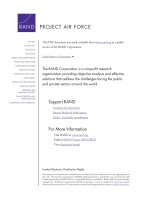
As for military applications, UAVs are also receiving greater emphasis in the
deployment of military operations. They are used mainly for border patrol and
surveillance missions [53-74], such as the Pioneer UAV (Figure 1.1) which is
currently operational in many countries worldwide. Another example is the
Predator UAV which is already operational in the US military, and has participated
in numerous combat missions and proven its high military value.
Figure 1.1. Photograph of the Pioneer UAV.
3
UAVs are not only being deployed closer to us in our daily activities, they are also
going to be deployed in faraway space exploration missions. This is because it is
still not feasible to have human astronauts exploring the atmospheres and terrains
of these planets. Therefore, UAVs will be excellent substitutes for these dangerous
tasks [75-77].
Currently, there are also research works on MAVs because they are much smaller
in size and also more lightweight, offering greater portability and superior combat
advantage in modern military warfare. Due to its miniature size, MAVs are able to
operate in close proximity to the point of interest with minimum risks of detection.
Thus, these miniature flight vehicles can provide surveillance teams with critical
information, such as warning troops before they enter a danger zone. Fitted into an
infantry soldier’s backpack, MAVs do not incur much significant load on the
combat personnel, but greatly enhance their combat capability. As no special
automotive vehicles are required for the transportation of MAVs, they can be
deployed in almost all kinds of terrain. One of the more promising works is the
Black Widow developed by AeroVironment, with a wingspan of 15cm and a mass
of only 56g (Figure 1.2).
Figure 1.2. Photograph of the Black Widow MAV.
4
Flight vehicle design involves making many iterative trade-off studies between
conflicting aerodynamic, stability, propulsion, performance and structural
requirements. For example, a fixed-wing aircraft with long wingspan has greater
aerodynamic efficiency but this imposes higher demands on its structural
provisions, usually resulting in a greater overall weight. With an increase in overall
weight, the aircraft must either have a larger wing area or more powerful
propulsion, which will result in greater overall weight, making the problem a
viscous cycle. Optimization has been recognized to be a powerful tool in the field
of aircraft conceptual design. At this preliminary design stage, it is desirable to
obtain the sizing and configuration layout for the flight vehicle quickly that will
meet closely the requirements of the designer. The use of genetic algorithms (GA)
as an optimization tool in aircraft design has shown great potentials [78-87].
1.1 Thesis objectives
This work aims to make use of genetic algorithms to automate the conceptual
design of small-scale rotary-wing UAVs/MAVs. The generic GA has been
modified to facilitate the optimization process. In order to minimize the research
development and product cost, the strategy adopted here is to employ commercial
off-the-shelf components in the design of the flight vehicles. Another reason for
using commercial-off-the-shelf components instead of developing miniature ones
is because of the unavailability of a team of researchers specializing in the different
component disciplines. Thus, whether the small-scale UAV obtained by the design
optimization can be small enough to match the MAV’s definition will depend on
the physical attributes of the commercial components that are available.
5
In addition, this thesis seeks to investigate the feasibility of an unconventional
configuration that is as easy to fabricate as the quadrotor but possibly more
compact, given the same range of component products to choose from.
Finally, with the encouraging results obtained in designing rotary-wing
UAV/MAVs, a design methodology is proposed for the aerodynamic shape design
of a fixed-wing MAV. A simple example is illustrated using a tailless fixed-wing
configuration.
1.2 Thesis organization
Chapter 2 describes an automated design methodology in the design of rotary-wing
UAV/MAV. This chapter focuses on the layout design and geometric sizing of a
standard single main rotor and tail rotor configuration. The design problem is to
obtain the most compact configuration subjected to physical and control
constraints.
Chapter 3 describes an automated design methodology for a more complex design
problem involving the layout design, geometric sizing and component selection of
a quadrotor UAV/MAV configuration. The design problem is to select a suitable
combination of components and position them such that it would be most compact
without violating the physical and control constraints.
6
Chapter 4 introduces an alternative unconventional configuration rotary-wing
UAV/MAV and explores its feasibility in producing UAV/MAVs smaller than the
quadrotor configuration given the same available range of component products to
choose from. A design methodology is also proposed to automate the design
process of this unconventional flight vehicle. A model simulation of the proposed
control mechanism is carried out to test the feasibilty of this new configuration.
Chapter 5 focuses on an automated design methodology for the conceptual design
of a fixed-wing UAV/MAV using genetic algorithms. A description is given on
how the design problem is formulated as a GA optimization problem. The GA
optimization is then compared with another nonlinear optimization package,
DONLP2.
Chapter 6 provides an overview of the workings of genetic algorithms (GA) and
why they are becoming more popular in solving numerous engineering
optimization problems. The modifications of the generic genetic algorithms to
enhance its performance will also be explained.
In chapter 7, the main ideas and contributions of this research work are
summarized, with some recommendations for future work.
7
2. Design Optimization of Single Main and Tail Rotar UAV/MAV
There are three main different types of UAVs and MAVs. The first type is the
traditional fixed-wing configuration. The disadvantage of fixed-wing configuration
MAV is that most of them need to fly typically at a minimum speed of more than
7m/s. With this flight speed constraint, Watkins [88] has commented that from his
experience, the use of fixed-wing MAVs at outdoor environment is still a challenge
at the present stage. Fixed-wing MAVs are more suitable for open terrain and not
suitable for maneuvering in a densely populated urban environment where there
are many buildings in close proximity.
The second type is the rotary-wing UAV/MAVs which can overcome this existing
limitation of fixed-wing UAV/MAVs. Unlike the fixed-wing MAVs which need to
fly constantly in order to stay airborne, the rotary-wing UAV/MAV has the distinct
advantage of being able to hover at a fixed spot, making it very difficult to be
detected. Moreover, rotary-wing UAV/MAVs have much greater maneuverability
which allows them to travel around even inside a building.
The third configuration which is also receiving a lot of academic interest is a kind
of insect-like flying machines [89-123]. The main motivation is to mimic the flying
mechanisms of natural creatures in hopes of achieving even smaller MAVs than
existing ones that have flown successfully. However, they are still in the
experimental phase and not ready for operational deployment.
8
This chapter focuses on the design methodology to automate the configuration
layout design and geometric sizing of a rotary-wing UAV/MAV that has a single
main rotor and tail rotor configuration. The objective of this design optimization
problem is to organize a given set of components and payloads, such that the
resulting flight vehicle has the most compact overall size, and still fulfils the given
physical and control constraints. A detailed discussion is presented to explain how
the rotary-wing MAV design problem can be formulated as a GA optimization
problem.
A low-cost approach to the development of a UAV/MAV can be achieved by
integrating the smallest available commercial-off-the-shelf components
(propulsion systems, sensors, power source, etc.). In this approach, one of the
biggest challenges is to position the aircraft components and payloads, to achieve
the smallest possible overall size, and still satisfy the physical and control
constraints present.
This design optimization problem cannot be solved in a straightforward manner as
the well-known knapsack, bin packing or container loading problem that other
researchers, such as Martello et al. [124] and Pisinger [125] have proposed. This is
because of the presence of additional constraints in the design problem. Firstly,
there is a constraint on the location of the overall center of gravity (CG) for
stability and control purposes. In addition, there is a need to impose a constraint on
the minimum moment arm of the tail rotor, so that it is sufficient to counterbalance
the torque produced by the main rotor. Moreover, some components such as the
9
main rotor assembly, tail rotor assembly and the rate sensors can only be mounted
with specific orientation, making the design process even more complicated.
Crossley and Laananen [126] have previously attempted to use genetic algorithms
in the conceptual design of rotary-wing aircraft. Their design focuses on
conventional helicopters, instead of miniature rotary-wing flight vehicles. One
common method in the layout design of rotary-wing flight vehicle is to vary the
positions of the components in a trial-and-error manner, until all the above-
mentioned constraints are satisfied. This approach is time consuming, and does not
guarantee that the size of the flight vehicle is the smallest possible. Therefore, the
objective of this study is to employ genetic algorithms to automate the layout
design and geometric sizing of a rotary-wing UAV/MAV.
2.1 Problem Formulation
In the optimization design problem, the propulsion, control, sensors components
and payload are modeled as rectangular blocks. The dimensions, length L, breadth
B and height H (refer to Figure 2.1) of each block are defined by the smallest
rectangular box that can enclose the component completely. These dimensions,
along with the mass and center of gravity information, of all the components are
measured and input into the optimization computer program.