Studies of different variations of optical tweezers with digital video microscopy
Bạn đang xem bản rút gọn của tài liệu. Xem và tải ngay bản đầy đủ của tài liệu tại đây (10.4 MB, 164 trang )
STUDIES OF DIFFERENT VARIATIONS OF OPTICAL
TWEEZERS WITH DIGITAL VIDEO MICROSCOPY
CHEONG FOOK CHIONG
(B. SCI (HONS.), NUS)
A THESIS SUBMITTED
FOR THE DEGREE OF DOCTOR OF PHILOSOPHY IN
SCIENCE
DEPARTMENT OF PHYSICS
NATIONAL UNIVERSITY OF SINGAPORE
ACKNOWLEDGEMENT
ACKNOWLEDGMENTS
The author wishes extend his heartfelt appreciation for the guidance and supervision of his
supervisor Associate Professor Sow Chorng Haur. His comments, suggestions and motivations over
the years have been invaluable to my research and development as a student.
He would also like to thank his family members and friends who have been very understanding and
patient with him over the past few years. Especially, his parent, brother, and grandmother, they have
always been there for him, watching him grow up from a curious boy to the inquisitive scientist he
is today.
Special acknowledgment goes to all his fellow friends of the Colloidal Lab Family, who have made
graduate life more meaningful and wonderful. He would specially thank Ms Fong Yuet Lai in her
constant moral support and contributions in the experiments. He is also very glad to have learnt
writing IDL programming with her. He is happy to have Mr Zhu Yanwu for the numerous
simulating discussions and suggestions on numerous topics in this thesis. He is in debt to Ms Lena
Liu for her contribution to his understanding of colloidal science and atomic force microscope. And
he is especially glad that she is such an encouraging and supportive friend whenever help is needed.
The author would like to thank Dr Yu T. and A/Prof Shen ZeXiang for introducing the hotplate
technique to grow metal oxide nanowires use in this thesis and for using optical travelator to align
CuO nanowires. And he is grateful to Mr B. Vaghese for his help and suggestions during the study
on focused laser writing of polymer. He would also like to thank Mr Lim K.Y. and his high school
student for their contribution of using the vibrating membrane for dynamic optical trapping. Special
ACKNOWLEDGEMENT
thanks also goes to other members in the family, without them, research life in the lab will not be as
colorful and unique.
It is also important to thank all the supporting staff of the department. Especially, Ms E.T. Foo and
friends in Engineering physics Laboratory for helping out in almost every aspect of the
administrative works, like most of the equipment purchases and loans; Mr. Tan and all the
technicians in physics workshops for helping out in the drilling of glass and technical support in the
constructions of the experimental samples and chambers; Dr Andrew A. Bettiol, Prof F. Watt and
friends in CIBA for their contributions to many great ideas and wonderful microlenses used in the
thesis; Prof Andrew Wee and the friends in surface science laboratory and NUSNNI for offering
assistances, advices, moral support and funding during the optical travelator project; A/Prof C.T.
Lim and friends in bioengineering corridor for providing with invaluable advises and support in
biological and cells manipulations with optical tweezers and nano-material studies; Ms Wang L.P
for providing the micro-channels and optimistic approach to life ; A/Prof Chin W.S and her students
for providing with some of the nano-materials used; A/Prof Ji W. and friends in the photonic
laboratory for their assistant in non-linear optics studies; Prof Tang S.H. and his students in helping
with the Raman and spectroscopy studies in some of the experiments; Prof Ong C.K. and friends in
the CSMM for their constant support and listening to his endless enquires for help; He would also
like to thank all the lab officers who have helped in the equipment loans and technical advises;
A/Prof Edward Teo and the teaching staffs of physics department has also given him the
opportunities to learn the art of teaching. Ms Sng W. L. and her officers in departmental office for
the endless administrative support; And to all friends, teachers, classmates, students and helpers
who have helped him to complete this thesis in one way or another, thank you all!
TABLE OF CONTENT
i
TABLE OF CONTENTS
• Acknowledgement
• List of publication
• Figures Caption
• Table of content
Page
1. Introduction 01
1.1. Introduction to optical tweezers 01
1.2. Theory of optical tweezers 02
1.3. Single optical tweezers setup 06
1.4. Scope and review 08
1.5. Summary 14
2. Multiple-beams Optical Tweezers 18
2.1. Introduction to multiple-beams optical tweezers 18
2.2. Dual beams optical tweezers 25
2.3. Multiple-Beams Optical Tweezers 27
2.4. Experimental setup 29
2.5. Result and discussion 31
2.6. Integration tweezers array 32
2.7. Summary 35
3. Optical Travelator 39
3.1. Introduction to line optical tweezers 39
3.2. Experimental setup 41
3.3. Optical manipulation and sorting with optical travelator 44
TABLE OF CONTENT
ii
3.4. Nanowires manipulation using optical travelator 52
3.5. Optical travelator in biology 56
3.6. Summary 57
4. Dynamic Optical Tweezers 61
4.1. Introduction to dynamic optical tweezers 61
4.2. Dynamic optical tweezers experimental setup 62
4.3. Theory of circular vibrating membrane 64
4.4. Results and discussions 69
4.5. Optical induced rotation 71
4.6. Multiple dynamic optical tweezers 77
4.7. Optical shuffle 79
4.8. Summary 82
5. Defects Remediation using Optical Tweezers 85
5.1. Introduction to colloidal science 83
5.2. Experimental setup 89
5.3. Colloidal interaction potential from pair-correlation function 91
5.4. Calculation of colloidal crystal free energy using DLVO theorem 95
5.5. Mediating colloidal crystal free energy using optical tweezers 100
5.6. Colloidal crystal remediation with a scanning optical tweezers 103
5.7. Summary 106
6. Optical tweezers and Direct Focused laser writing
6.1. Introduction to focus laser writing 110
6.2. Experimental setup 111
6.3. Focus laser writing on nanomaterials 113
6.4. Focus laser writing on polymer 117
6.5. Applications 120
TABLE OF CONTENT
iii
6.6. Summary 125
7. Conclusion 130
• Appendix A: Principle behind optical trapping force in optical tweezers.
SUMMARY
iv
SUMMARY
In this thesis, different variations to optical tweezing and their different applications are
presented. Optical tweezers coupled with digital video microscopy is a powerful tool to
study the mechanics and dynamics of various mescopic systems. The objective of the
thesis is to integrate optical microscopy with more complex optical designs to construct
different variations of optical tweezers and study their plausible applications. The thesis
starts with a brief introduction to the basic principles and construction of an optical
tweezers. Then I introduced different techniques to construct multiple optical tweezers,
line optical tweezers and dynamic optical tweezers. I have applied these various optical
tweezers techniques to demonstrate various optical manipulation and optical sorting of
colloidal particles. In addition, I have successfully demonstrated the use of dynamic
optical tweezers system to two-dimensional colloidal crystals and have yielded new
insights into the physics of soft-condense matter physics.
LIST OF PUBLICATION
vi
LIST OF PUBLICATIONS
INTERNATIONAL SCIENTIFIC JOURNALS
1. Cheong F.C. and Sow C.H., Defects Remediation using Optical Tweezers (in
preparation)
2. Cheong F.C., Varghese B., Zhu Y.W., et al. WO
3-x
nanorods synthesized on a hotplate:a
simple and versatile technique Journal of Physical Chemistry (Submitted) (2007)
3. Cheong FC, Varghese B, Sindhu S., et. al. , Direct Removal of SU-8 using focused laser
writing, APPLIED PHYSICS A, Material Science and Process 87 (1): 71-76 APR
(2007)
4. Cheong FC, Varghese B, Sindhu S., et. al., Manipulation and assembly of CuSx
dendrites using optical tweezers, JOURNAL OF SOLID STATE PHENONMENA, 121-
123: 1371-1374 (2007)
5. Cheong F.C., Zhu Y.W., Varghese B., Lim C.T., Sow C.H., Direct Synthesis of
Tungsten Oxide Nanowires on Microscope Cover Glass, ADVANCES IN SCIENCE AND
TECHNOLOGY 51: 1-6 (2006)
6. Zhao Y. , Zhai W.C., Seah W. L., Cheong F.C, Sow C.H, Scanning Mirror on a vibrating
Membrane for Dynamic Optical trapping APPLIED PHYSICS B: Laser and optics (2006)
(Accepted)
7. Varghese B., Cheong FC, Sindhu S., et. al. , Size Selective Assembly of Colloidal
Particles on Template by Directed Self Assembly Technique, LANGMUIR 22 (19): 8248-
8252 SEP 12 2006
8. Hanafiah N. B. M., Renu R., Ajikumar P. K., Sindhu, S. Cheong F.C., et al. Amphiphilic
Poly(p-phenylene)s for Self-organized Porous Blue Light-Emitting Thin Films,
ADVANCED FUNCATIONAL MATERIALS 16 (18) , 2340-2345, 3 NOV 2006
9. Cheong FC, Sow CH, A.T. Wee, et. al., Optical travelator: Transport and dynamic
sorting of colloidal microshperes with an asymmetrical line optical tweezers, APPLIED
PHYSICS B-LASERS AND OPTICS 83: 121-125 Feb 2006
10. Yu T, Sow CH, Gantimahapatruni A, Cheong FC, et al. Patterning and fusion of CuO
nanorods with a focused laser beam, NANOTECHNOLOGY 16 (8): 1238-1244 AUG
2005
LIST OF PUBLICATION
vii
11. Saurakhiya N, Zhu YW, Cheong FC, et al.Pulsed laser deposition-assisted patterning of
aligned carbon nanotubes modified by focused laser beam for efficient field
emission CARBON 43 (10): 2128-2133 AUG 2005
12. Bettiol AA, Sum TC, Cheong FC, et al.A progress review of proton beam writing
applications in microphotonics, NUCLEAR INSTRUMENTS & METHODS IN PHYSICS
RESEARCH SECTION B-BEAM INTERACTIONS WITH MATERIALS AND ATOMS
231: 364-371 Sp. Iss. SI APR 2005
13. Zhu YW, Yu T, Cheong FC, et al. Large-scale synthesis and field emission properties of
vertically oriented CuO nanowire films NANOTECHNOLOGY 16 (1): 88-92 JAN 2005
14. Yu T, Cheong FC, Sow CH The manipulation and assembly of CuO nanorods with line
optical tweezers NANOTECHNOLOGY 15 (12): 1732-1736 DEC 2004
15. Zhu YW, Cheong FC, Yu T, et al. Effects of CF4 plasma on the field emission properties
of aligned multi-wall carbon nanotube films CARBON 43 (2): 395-400 2005
16. Tan BJY, Sow CH, Lim KY, Cheong FC, et al. Fabrication of a two-dimensional
periodic non-close-packed array of polystyrene particles JOURNAL OF PHYSICAL
CHEMISTRY B 108 (48): 18575-18579 DEC 2 2004
17. Sow CH, Bettiol AA, Lee YYG, Cheong FC, et al. Multiple-spot optical tweezers
created with microlens arrays fabricated by proton beam writing APPLIED PHYSICS B-
LASERS AND OPTICS 78 (6): 705-709 APR 2004
18. Cheong FC, Lim KY, Sow CH, et al. Large area patterned arrays of aligned carbon
nanotubes via laser trimming NANOTECHNOLOGY 14 (4): 433-437 APR 2003
19. Lim KY, Sow CH, Lin JY, Cheong FC et al. Laser pruning of carbon nanotubes as a
route to static and movable structures ADVANCED MATERIALS 15 (4): 300-303 FEB
17 2003
INTERNATIONAL CONFERENCE PROCEEDINGS
20. F.C. Cheong and Sow C.H., Acoustic Controlled Dynamic Optical Tweezers, Proceeding
in SPIE Symposium on Optics and Photonics, San Diego 2006
21. F.C. Cheong, et. al., Optical Travelator: Transport and Dynamic Sorting of Colloidal
Microspheres with an Asymmetrical Line Optical Tweezers Proceeding in International
Conference for Material and Advanced Technology (ICMAT) 2005
22. F.C. Cheong et.al, Direct Focused Fabrication of SU-8 microstructures, Proceeding in
2
nd
MRS Conference on Advanced Materiald 2006
LIST OF PUBLICATION
viii
23. F.C. Cheong, et. al.,Manipulation and assembly of CuSx dendrites using optical
tweezers Proceeding in 1
st
Nano conference in Beijing (ICMAT) 2005
24. F.C. Cheong, et. al., Multiple-spot optical tweezers created with microlens arrays,
Proceeding in 1st MRS Conference on Advanced Material 2004
25. Yu T., F.C. Cheong, et. al., Manipulation and assembly of CuO nanorods with line
optical tweezers , Proceeding in 1
st
MRS Conference on Advanced Material 2004
26. F.C. Cheong, et. al., Studies of Laser Modification and Fabrication of Patterned &
Extended CNTs Array, Proceeding in International Conference for Material and
Advanced Technology (ICMAT) 2003
BOOK CHAPTERS
27. C.H. Sow, K.Y. Lim, F.C. Cheong, N. Saurakhiya, et. al., Micro-Topiary – Laser
Pruning of Carbon Nanotubes Arrays (Fabrication of static and movable 3 D CNTs
structures via Laser Trimming) Progress in Nanotechnology Research, Nova Science
Publishers, 2005
FIGURES CAPTION
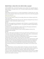
Fig.1.1 Schematic of how optical tweezers is used to trap objects. The intensity gradient of the
laser beam will pull particles towards the focal point, while the scattering force will push the
particles along the optical axial. When optical gradient force balances the scattering force,
particles can be trapped near the focal point. [15]
Fig. 1.2 Ray optics diagram tracing out the path of light rays traversing through a dielectric
sphere with refractive index (a) larger than medium and (b) smaller than the medium [2].
Fig. 1.3 Schematic illustration for our optical tweezers set up used in this work.
Fig. 2.1 (a) Schematic for a dual-beams optical tweezers setup (b) Photographs of the dual-beam
optical tweezers setup (c) Optical micrograph of 1.2µm polystyrenes beads dispersed in aqueous
medium. (d) Optical micrograph of two optical tweezers within a microscopic view trapping four
1.2µm polystyrenes beads dispersed in aqueous medium
Fig. 2.2(a) Schematic of the processing steps for the fabrication of the thermal reflow microlenses
array. (b) Optical micrograph of a top view of a square array of microlenses. The diameter of the
lens is about 180 µm. (c) Diffractive laser spot pattern generated after laser from a He-Ne Laser
wavelength (λ=632.8nm) passes through the microlenses array.
Fig. 2.3 Schematics of the experimental setup showing the interior of an inverted microscope. A
laser beam passes through a microlens array and the resultant light pattern is focused onto a
sample chamber consisting of aqueous suspension of polystyrene microbeads.
Fig. 2.4 (a) and (b) Optical microscope images of different assemblies of the microbeads
achieved via multiple-spots optical tweezers array. The spatial period of the microbeads array is
about 3.2µm. (c) A mosaic of letters formation by trapped microbeads. (d) and (e) Two snapshots
of a microbead configuration during an anti-clockwise rotation. The diameters of the microbeads
shown are: (a)(d)(e) 1.9 µm and (b)(c) 1.2 µm. Video clips of the formation and rotation of the
microbead assembly can be found at [18]
Fig 2.5 (a) Schematic diagram labeling various parameters associated with the microlens. (b)
Optical Micrograph of array of microlenses used in this application. The lenses form a hexagonal
array with a lattice spacing of 25 µm. (c) Schematic (not to scale) of a sample cell where the array
of microlenses is built into the sample chamber. (d) Optical micrograph of a close-up view of the
array of microlenses. (e) Viewing plane about 150 µm from (d) showing the bright focused laser
spots. Microbeads can be found trapped at the local beam intensity maxima. The diameter of the
microbeads is 5.1 µm. Video clip of the trapping of the microbeads by this built-in optical
tweezer array can be found at [18]
Fig. 3.1 (a) Schematic of a double line optical tweezers system and a sample cell that was
coupled with electrodes for electrophoresis. The inset shows the schematic of the intensity profile
after a parallel beam with Gaussian intensity profile passes through the cylindrical lens resulting
in the creation of a skewed intensity profile. (b) Measured laser power profile after passing
through a cylindrical lens. The region bound by the dotted lines was focused by the objective lens
to create the line optical tweezers.
Fig. 3.2 (a) Optical micrograph of a 2-D system comprising silica microspheres (diameter: 1.58
µm) under the influence of a single optical travelator. (b) Optical micrograph showing herding of
polystyrene microspheres (diameter: 1.2 µm) using two optical travelators. The dotted line boxes
outline the region where the optical travelators affect the microspheres. Scale bars=10 µm.
Videoclips of the optical travelator in action can be found in the supplementary material [34].
Fig. 3.3 (a) Optical micrograph of the colloidal system. The arrows indicate the direction of flow
(solid arrow) of the particles and the direction of the optical travelator (dotted arrow).
θ
= 74
o
and
scale bar = 40 µm. Trajectories of the microspheres in the same region of flow for a binary
system of 1.1 µm (thin dotted line) and 3.2 µm (thick lines) polystyrene spheres at an applied
voltage of (b) 10V, (c) 50V and (d) 90V. (e) A plot of the particle deflections and net sorting
efficiencies versus the applied voltage. (f) A plot of the particle deflections and net sorting
efficiencies versus the measured velocity of the particles.
Fig. 3.4 (a) Optical micrograph of a snapshot of the colloidal system. The arrows indicate the
direction of flow of the particles and the direction of the optical travelator.
θ
= 40
o
and scale bar =
40 µm. Trajectories of the microspheres in the same region of flow for a binary system of 1.1 µm
(thin dotted line) and 3.2 µm (thick lines) polystyrene spheres at an applied voltage of (b) 5V, (c)
50V and (d) 90V. (e) A plot of the particle deflection and net sorting efficiencies versus the
applied voltage. (f) A plot of the particle deflection and net sorting efficiencies versus the
measured velocity of the particles.
Fig. 3.5 Plot of maximum net efficiency of sorting against the angle θ.
Fig. 3.6. Optical micrographs showing (a) CuO nanorods in the field of view in the absence of the
line tweezers; (b) Nanorods lined up in a single line due to the influence of the line tweezers.
Scale bars = 15 µm. Videoclips of the nanorods manipulation process can be found in website
[27].
Fig. 3.7 Sequential optical micrographs of the manipulation of nanorods into a cross formation
with the line tweezers. Scale bars = 15 µm. Videoclips of the nanorods manipulation process can
be found in website [27].
Fig. 3.8(a-c) Sequential optical micrographs of manipulating CuO nanorod to bridge across Au
electrodes with line tweezers. (d) Optical Micrographs in transmission mode. Scale bars = 15 µm.
Videoclips of the trapping and manipulation of the CuO NW across the electrodes can be found in
website [27].
Fig. 3.9 Optical micrograph of yeast cells trapped and transported using the optical travelators.
Supplementary video clip of yeast cells trapped and translated in optical travelator can be found
in ref [21].
Fig. 4.1(a) Schematic of the vibrating membrane scanning mirror optical tweezers setup. The dotted
lines in the schematic indicated the possible laser paths steered by the scanning mirror (b)
Photograph of the experimental setup and the green dotted line indicates the optical train of the laser
beam used.
Fig. 4.2 (a) Photographic image of ellipsoidal laser beam pattern created by this technique (b)
Corresponding optical micrograph of the resultant ellipsoidal optical trap formed to trap an
assembly of 1.58µm silica microspheres. (c) Photographic image of a line laser beam pattern
created by this technique. (d) Corresponding optical micrograph of the resultant line optical trap
formed to trap a row of 1.58µm silica microspheres (Scale bar= 5µm).
Fig 4.3 Schematic of a vibrating membrane used as a scanning mirror system to direct incident
laser beam. Computer simulated solution for z = J
1
(k
12
r) cos(θ) sin(w
12
t) is used for this
illustration. (a) Incident laser beam is reflected off the centre of a vibrating membrane surface. (b)
Incident laser beam is directed to another position δx from the original position after time t.
Fig. 4.4 (a) Plot of size of the optical pattern verses the amplitude of loudness of the applied
sound. (b) Plot of membrane frequencies of the laser beam verse applied sound frequencies
Fig. 4.5 (a-h) Optical micrographs of one optically trapped microspheres orbiting in the optical
vortex. (Each image is 200ms apart from each other). (i) x-y position trace of one sphere over a
period of 20s. (j) y-t plot of the time variation of the particle’s y-displacement over a period of
20s. Video clips of sphere rotation within an optical vortex generated by vibrating membrane
acting as an oscillating source for a scanning mirror are available in [31].
Fig. 4.6 Plot of circular optical trap’s radius R verses rate of rotation Ω. Inset: Plot of ln(R) verses
ln(Ω) . The red line in the plot is a 1/R
3
polymer fitting to the experimental data. And the black
line in the inset plot is a linear line fit for a ln(Ω) ln(R) with gradient equals to 3.
Fig. 4.7 (a) Optical micrographs showing an assembly of 9 spheres in a ring optical trap. (b) Plot
of the trajectory of nine spheres traced over a period of 20s. (c) Plot a single sphere, y-
displacement against time, traced over a period of 20s. (d) Plot of rotation rate verses laser power.
Video of optical vortices created by this method can be found in the supplementary reference
webpage [31].
Fig. 4.8 (a) Plot of the rotational rate against the occupation number of spheres at different laser
power (b) Plot of the rotational rate against the applied laser power.
Fig. 4.9 (a) Photographic image of a multiple spots array diffraction pattern generated when a
532nm laser is reflected off a multiple square array diffractive optical element (DOE). (b) Optical
micrograph of multiple beams optical tweezers array trapping 1.58µm silica microspheres. (c)
Photographic images of multiple spots array becomes multiple lines array when the membrane is
driven by a sound source of 150Hz. (d) Optical micrograph of the resultant multiple-lines optical
tweezers array aligning multiple pairs of 1.58 µm silica bead to a fixed orientation defined by the
trap. (Scale bar =5 µm)
Fig. 4.10 (a) Schematic of a system comprising of two scanning mirrors using two separated
vibrating membranes optical tweezers setup. The dotted lines in the schematic indicated the
possible laser paths steered by the scanning mirror (b-g) Optical micrographs sequences showing
this technique shuffling an assembly of 4 silica (diameter 1.58µm) microspheres (Each frame is
0.2s apart.) The black cross indicates the same sphere that was traced over the period of 1s. Video
clips of shuffling of spheres assembly by the coupled vibrating membrane scanning mirror
generated optical traps are available in ref [16]
Fig. 5.1(a) Schematic of the experimental setup used. (b) Optical micrograph of SiO
2
sphere trapped
in a ring optical trap. (c) Displacement time plot of the trapped particle trajectory.
Fig. 5.2(a) Optical micrograph of an assembly of 1.58µm silica microspheres dispersed in water.
(b) Pair correlation function obtained from averaging over optical micrographs of microspheres at
ambient condition. Particle interaction potential U(r) for the system with the line is fitted to the
DLVO theory. Insert is a plot of is a best linear fit ln(U(r)) verses r. (d) Optical micrograph of a
colloidal crystal self assembled by the silica microspheres in the same system.
Fig. 5.3 (a) Optical micrograph of a two dimensional colloidal crystals. (b) Identified centroids of
the spheres in (a). (Inset) Schematic representation of how the strain energy is calculated in such
a colloidal lattice. Circle represents position of a sphere. Triangle symbol is used to depict a
position of a sphere with respect to its neighbours. Then the region in the hexagonal is divided
into many small grid points. Among the grid points, cross marks the preferred position of the
sphere in absence of any strain.
Fig. 5.4 (a) and (b) Optical micrographs of colloidal lattices. (c) and (d) Maps of the spheres
position landscape. Circles highlights position where the free energy is larger than 0.18k
B
T
Fig. 5.5(a) and (b) are plots of the δE distribution measured of the two-dimensional colloidal
crystal systems for Fig. 5.4(a) and Fig. 5.4(b) respectively. (c) and (d) are plots of ln(P(δE))
versus δE and the best linear fit to the data points for the corresponding results in (a) and (b)
respectively.
Fig. 5.6(a) Optical Micrograph of a colloidal crystal region before introduction of optical
tweezers (b) Same region of the colloidal crystal during the introduction of a rotating optical
tweezers and (c) Same region of the colloidal crystal after the introduction of the optical tweezers
(d) Time evolution of the characteristic strain energy during and after the introduction of the
optical tweezers. Inset is the ln(E(strain)) versus time plot of the relaxation process, with the bold
black line as the best linear fit.
Fig. 5.7 Voronoi construction on a colloidal lattice that was disturbed by a rotating optical
tweezers. A domain island surrounded by grain boundary is highlighted. The evolution of the
grain as the tweezers was swept downwards is shown from (a) to (g). Each images is separated
by1s between them.
Fig. 5.8 (a) Plot of total number of fivefold and sevenfold disclinations in a system against time
as an optical vortex scanned across a two dimensional colloidal crystal. (c) Plot of strain energy
of the system against time. (b) and (d) are Voronoi Constructions of the colloidal lattice region
before and after the laser scanned through the embedded domain island respectively.
Fig. 6.1 Schematic of the optical microscope-focused laser beam setup.
Fig. 6.2 (a) Side view of Electron Micrograph of carbon nanotubes array that is trimmed by
focused laser (λ=632nm) under a 50X objective lens at different focal point in the z-axis. (b)
Electron micrograph of a “NUS” pattern created by laser writing on carbon nanotubes array. (c)
Electron micrograph of 10 µm x10µm square micro-pillars created by focused laser writing. (d)
Electron micrographs of periodic carbon nanotubes (view at 25
o
) micro-walls array created by
focused laser writing. (Scale bar= 10 µm)
Fig. 6.3 (a) Electron micrograph side view of CuO nanowires array on trimmed at different laser
power. (Scale bar= 20µm) (b) Electron micrograph top view of the CuO nanowires pruned under
focused laser writing. Microballs were seen on the top ends of the trimmed nanowires (Scale bar=
2µm) (c) Transmission Electron Micrograph of the microball and the CuO nanowire interface
((Scale bar= 2nm) (d) Electron micrograph of using focused laser to micro solder two CuO
nanowires together. (Scale bar= 1µm)
Fig. 6.4 (a) Absorbance spectra of the SU-8 photoresist after different post-baking temperatures.
(b) An atomic force micrograph of the SU-8 surface (60x60) µm
2
modified by focused laser
writing to create an array of holes. (c) Plot of SU-8 channel width cut by laser verses different
laser power for two different types of objective lens used. (b) An atomic force micrograph of the
SU-8 surface (60x60) µm
2
modified by focused laser writing to create an array of pillars.
Fig. 6.5(a) and (b) Optical micrographs of periodic patterns created by focused laser writing on
SU-8 photoresist. Inserts shows the diffracted patterned after a single spot laser passed through
each respective optical element. (c) Schematic of using focused laser writing to fabricate more
complex microstructures. (d) Atomic force micrograph of a focused laser generated “multiple
pyramids” SU-8 array.
Fig. 6.6 (a) Electron micrographs of laser trimming of SU-8 film through a transparent glass
substrate (scale bar =1 µm). (b) A network of undercutting of SU8 to form a network of micro-
channels (scale bar=10µm). (c) Electron micrograph of SU-8 ‘m’-shaped three-dimensional
microstructure (scale bar=10µm) (d) Electron micrograph of another multiple stepped array of
SU-8 ‘U’-shaped microstructure (scale bar =10 µm).
Figure 6.7 (a)(i) Schematic of randomly dispersed nano or submicron rods or wires on SU-8 thin
film with glass as supporting substrate (ii) Using laser writing technique to create the ZnO rod
bridging across two SU=8 platform (b) Electron micrograph of ZnO rod bridging across two SU-
8 platform viewed at a tilted angle of 40 degrees. The inset is a top view of the same ZnO (c) (i)
Schematic of using laser writing on SU-8 to construct micro-channels for deposited nanowire. (ii)
Couple with magnetic field a droplet of nickel nanowires can be forced to bridge across the
channel creates. (d) Electron micrograph of one chain of nickel nanowires deposited across two
channels created by focused laser writing (scale bar =1µm)
To my grandmother
(1916 ~ 2007)
Chapter 1 Introduction
1
C h a p t e r 1
INTRODUCTION
1.1 INTRODUCTION TO OPTICAL TWEEZERS
About twenty years ago, Arthur Ashkin, Steven Chu and co-workers in AT&T Bell
Laboratories introduced the novel approach of using photons to manipulate microscopic and sub-
microscopic particles [1, 2] known as optical manipulation. Now, this technique has been an
important tool in the scientific community that has revolutionized the way we use optical
microscopes. Today, a single focused laser manipulation of microscopic object, which is
generally recognised as Optical Tweezers, has been utilized in a wide variety of research fields,
like biology [3,4], soft-condensed matter physics [1, 2] and medical science [3, 4]. This tool
opens up options for trapping, manipulating, and sorting particles based on the forces exerted by
light at the level of the mesoscopic world. Optical micromanipulators provide unprecedented,
non-invasive access to the microscopic world that is of great interest to the scientific and
engineering community. Therefore, it is essential to continue our investigation and development
of this technique in order to obtain the rich scientific knowledge and opportunities unearthed by
optical tweezers.
In this thesis, I will present different variations of optical tweezing and their different
applications. The main objective of the thesis is to demonstrate the integration of optical tweezers
with more complex optical designs, at one or many points, to construct different variations of
optical tweezers. From a single spot optical tweezers, I expand the system to include two spots
optical tweezers, multiple spots optical trapping and line optical tweezers. For each variation of
optical trapping, I have explored the possible applications for various colloidal systems. Besides
simple static optical tweezers of different variations, I have also investigated the option of using
Chapter 1 Introduction
2
audio waves on a rubber membrane to construct dynamic optical trapping. By using these various
optical tweezers systems and video microscopy, I have investigated the possibility of applying
optical forces to study the underlying principles in soft-condensed matter physics. At the end of
the thesis, I have also utilized the standard optical tweezers setup as a lithography tool to induce
photochemical transformations and sublimation on irradiated material. Using this technique of
focused laser writing, I am able to construct useful two and three-dimensional microstructures.
1.2 THEORY OF OPTICAL TWEEZERS
Optical tweezers use forces exerted by a strongly focused beam of light to trap micron
and sub-micron objects. The theories of optical trapping are generally classified into two regimes.
For dielectric particles of radius a, much larger than the wavelength of light λ (a >> λ) most of
the theories are based on Mie’s approach. Whereas for particle sizes much smaller than the
wavelength of the light used (a << λ), the theories use Rayleigh’s approach. By using optical
tweezers, both regimes have been thoroughly investigated theoretically [1- 6]. In this thesis, I will
briefly look into the physics behind both regimes.
In the Rayleigh regime, when a very small dielectric object is exposed to an incident
laser, an electric dipole moment develops in response to the photon’s electric field. The resultant
optical force created by such an interaction between particle and radiation can be described by the
following equations [3]
F(optical) = F (scattering) + F (gradient)………………… ………… (1.1)
F(scattering) is the optical scattering force due to radiation pressure. When incident light
is scattered by the dielectric material (sphere with radius a), this force [2] is
F(scattering) =
!
I
o
"
n
m
c
…………………………………………………….(1.2),
where I
o
is the intensity of the laser,
!
"
=
128
#
5
a
6
3
$
4
m
2
%1
m
2
+ 2
is the scattering cross section,
λ
is the
Chapter 1 Introduction
3
wavelength of the incident monochromatic light, m =
!
n
p
n
m
is the ratio of the index of refraction of
the particle (n
p
) with respect to the refractive index of the medium (n
m
), and c is the speed of light
in vacuum.
Fig.1.1 Schematic of how optical tweezers is used to trap objects. The intensity
gradient of the laser beam will pull particles towards the focal point, while the
scattering force will push the particles along the optical axial. When optical
gradient force balances the scattering force, particles can be trapped near the
focal point. [15]
F(gradient) is the time average optical gradient force that arises from the interaction of
the induced dipole with the inhomogeneous optical field
F(gradient) =
!
2
"
#
cn
m
$I
o
………………………………… (1.3),
where
!
"
= n
m
2
a
3
m
2
#1
m
2
+ 2
$
%
&
'
(
)
is polarizability of the dielectric sphere.
The total optical induced force acting on a small dielectric sphere is determined by the
competition between the optical gradient force and the optical scattering force. The optical
Chapter 1 Introduction
4
gradient force attracts particles to the beam’s focal point, while the scattering force pushes the
particles along the beam’s axis like air blowing down a hollow tube as shown in Fig 1.1. For a
tightly focused laser beam, when the gradient force overcomes gravitational and scattering force
associated with a dielectric particle in the vicinity of the focus, the particle is subjected to a force,
directed toward the region of highest intensity as shown in Fig. 1.1. Hence, to secure stable
optical trapping, we require the optical gradient force to be large. This can be achieved if the
beam converges and diverges strongly towards and away from the focal point, thereby creating a
large enough intensity gradient
!
"I
o
to produce a large optical gradient force (Fig. 1.1). In
experiments, to achieve a sufficient gradient force, we need a high numerical aperture and an
aberration corrected optical microscope objective lens to tightly focus a laser beam to a tight spot.
The three-dimensionally trapped microscopic particle in such an optical system, will reach a
stable equilibrium slightly below the focal point. A detail derivation of the optical gradient force
from Maxwell’s Equation can be found in appendix A of this thesis.
In the Mie regime, when a large dielectric object is exposed to an incident laser, the
object acts as a lens [4, 5]. As shown in Fig 1.2 (a), the dielectric sphere refracts the rays of light
and redirects their photons’ momentum from their initial path according to Snell’s Law. From
Newton’s second law, the rate of change of momentum of the light results in a force on the
photon, which according to Newton’s third law will have resultant force acting on the sphere. In
an optical tweezers system, such recoil is substantial enough to pull/push an object, with weight
around pico to femto Newton range towards/away from the focal point according to the refractive
index difference between the object and the medium. In Fig. 1.2(a) the sphere has a refractive
index larger than the medium, thus it induces a resultant force pulling it towards the focal point.
In Fig. 1.2(b), an air bubble with a refractive index lower than water will experience a force that
will push it away from the focal point of the laser beam.
Chapter 1 Introduction
5
Fig. 1.2 Ray optics diagram tracing out the path of light rays traversing through a
dielectric sphere with refractive index (a) larger than medium and (b) smaller
than the medium [2].
If the photons are not transmitted through the object and scattered off the surface, the
momentum transferred from the photons in the beam, tend to push particles down the optical axis.
As in the case of a metallic object in optical tweezers, the photons are either absorbed or scattered
backward by the metallic surface. By conservation of momentum, the metallic object will gain a
forward momentum if photons are scattered back. And this will result in the sphere being pushed
along the optical beam axis.
For particle size around the wavelength of the incident light, a theoretical explanation for
the physics behind the optical trapping is still being developed. Current works are based on
generalized Lorenz-Mie diffraction theory [7], vectorial diffraction theory [8], and computer
simulation techniques like using finite-differential-time-domain (FDTD) algorithm [9]. Using all
these methods, the analytical solution for optical trapping on a spherical dielectric particle by an
arbitrary focused laser beam consistently matches the experimental value.
Chapter 1 Introduction
6
1.3 SINGLE OPTICAL TWEEZERS SETUP
Many of the most useful optical manipulation techniques are derived from single-beam
optical traps known as optical tweezers. An inverted optical microscope Nikon TE300, with an oil
immersion microscope objective CFI S Flour 100X (numerical aperture, NA=1.25) is used in this
work. The optical train (Fig. 1.3) consists of two Keplerian telescopes and a beam-steering
mirror. The design goal is simplicity and optical efficiency. The aim of the optical setup is to
have strong particle confinement to the focal plane. A CNI MGL-W diode laser of wavelength
532nm (maximum output power = 1.68W) that provides collimated CW single mood laser source
is chosen for optical trapping. Theoretically, optical tweezers may operate with lasers of any
wavelength. The choice of the laser will depend mainly on the type of experiments. It is advisable
to use lasers in the near infrared (800nm ~1064nm) when doing biological based experiments so
as to minimize photo damage to the sample [17].
In Fig. 1.3, the 532nm laser is bounced off two mirrors and directed through a set of
telescopic lens to expand the beam to the optimal size for the beam-steering mirror to deflect onto
another set of telescope assembly, which guide the beam into the side port of the inverted
microscope. This set of lenses configuration is added to the optical beam path, before entering
into the microscope to correct for any focusing discrepancy between the focused laser and the
viewing plane. This can help ensure that the back aperture of the objective is filled/ over-filled to
optimize the performance of the optical trap [14]. This arrangement can also help to keep a
steering laser beam within the back aperture during beam manipulation. The laser is then
reflected off a beam splitter within the microscope, passed through the 100x objective lens and
focused tightly as illustrated in Fig. 1.3.
Chapter 1 Introduction
7
Fig. 1.3 Schematic illustration for our optical tweezers set up used in this work.
The objective lens usually selected for optical trapping will have a high numerical
aperture (N.A.= 1.25 or larger) for generating a strong gradient in the intensity variation [5].
Light from the illuminated particles will be collected by the CCD camera [10] for imaging and
recording. The images can be recorded by a computer for further analysis as shown in Fig. 1.3.
In order to determine the optical trapping force directly, the instrument must be
calibrated. In the viscous drag force calibration, the video tracking of the bead’s motion can be
converted to absolute distance by calibrating the CCD camera pixels with a standard micrometer
ruler (TEM copper grid with 2000 mesh by Agar Scientific was used). A picture identification
program is written in Research system Inc., IDL software Version 5.5. This whole method of
digitising video images of optical micrographs is also known as Digital video Microscopy. And I
will be using this technique to capture and analyse most of our data presented in this thesis.