Design methodologies for instruction set extensible processors
Bạn đang xem bản rút gọn của tài liệu. Xem và tải ngay bản đầy đủ của tài liệu tại đây (2.08 MB, 162 trang )
DESIGN METHODOLOGIES FOR
INSTRUCTION-SET EXTENSIBLE
PROCESSORS
YU, PAN
NATIONAL UNIVERSITY OF SINGAPORE
2008
Design Methodologies for Instruction-Set
Extensible Processors
Yu, Pan
(B.Sci., Fudan University)
A thesis submitted for the degree of Doctor of Philosophy
in Computer Science
Department of Computer Science
National University of Singapore
2008
List of Publications
Y. Pan, and T. Mitra, Characterizing embedded applications for instruction-set
extensible processors, In the Proceedings of Design Automation Conference (DAC),
2004.
Y. Pan, and T. Mitra. Scalable custom instructions identification for instruction-set
extensible processors. In the Proceedings of International Conference on Compilers,
Architectures, and Synthesis for Embedded Systems (CASES), 2005.
Y. Pan and T. Mitra. Satisfying real-time constraints with custom instructions. In
the Proceedings of International Conference on Hardware/Software Codesign and
System Synthesis (CODES+ISSS), 2005.
Y. Pan and T. Mitra. Disjoint pattern enumeration for custom instructions iden-
tification. In the Proceedings of International Conference on Field Programmable
Logic and applications (FPL), 2007.
Acknowledgement
I would like to thank my advisor professor Tulika Mitra for her guidance. Her
broad knowledge and working style as a scientist, care and patience as a teacher
have always been the example for me. I feel very fortunate to be her student. I
wish to thank the members of my thesis committee, professor Wong Weng Fai,
professor Samarjit Chakraborty and professor Laura Pozzi for their discussions and
encouraging comments during the early stage of this work. This thesis would not
have been possible without their support.
I would like to thank my fellow colleagues in the embedded system lab. They
are, Kathy Nguyen Dang, Phan Thi Xuan Linh, Ge Zhiguo, Edward Sim Joon, Zhu
Yongxin, Li Xianfeng, Liao Jirong, Liu Haibin, Hemendra Singh Negi, Hariharan
Sandanagobalane, Ramkumar Jayaseelan, Unmesh Dutta Bordoloi, Liang Yun, and
Huynh Phung Huynh. The common interests shared among the brothers and sisters
of this big family have been my constant source of inspiration. My best friends Zhou
Zhi, Wang Huiqing, Miao Xiaoping, Ni Wei and Ge Hong have given me tremendous
strength and back up all along. And most importantly, thanks to Yang Xiaoyan,
my fiancee, for her accompany and endurance during all these years.
My parents and my grand parents, they raised, inspired me, and always stand
by me no matter what. My love and gratitude to them is beyond words. I wish my
grand parents in heaven would be proud of my achievements, and to hug my parents
tightly in my arms — at home.
ii
Contents
List of Publications i
Acknowledgement ii
Contents iii
Abstract ix
List of Figures x
List of Tables xv
1 Introduction 1
1.1 Specialization . . . . . . . . . . . . . . . . . . . . . . . . . . . . . . . 2
1.1.1 Inefficiency of General Purpose Processors . . . . . . . . . . . 3
1.1.2 ASICs — the Extreme Specialization . . . . . . . . . . . . . . 5
1.1.3 Software vs. Hardware . . . . . . . . . . . . . . . . . . . . . . 6
iii
CONTENTS iv
1.1.4 Spectrum of Specializations . . . . . . . . . . . . . . . . . . . 6
1.1.5 FPGAs and Reconfigurable Computing . . . . . . . . . . . . . 11
1.2 Instruction-set Extensible Processors . . . . . . . . . . . . . . . . . . 14
1.2.1 Hardware-Software Partitioning . . . . . . . . . . . . . . . . . 16
1.2.2 Compiler and Intermediate Representation . . . . . . . . . . . 18
1.2.3 An Overview of the Design Flow . . . . . . . . . . . . . . . . 19
1.3 Contributions and Organization of this Thesis . . . . . . . . . . . . . 20
2 Instruction-Set Extensible Processors 24
2.1 Past Systems . . . . . . . . . . . . . . . . . . . . . . . . . . . . . . . 24
2.1.1 DISC . . . . . . . . . . . . . . . . . . . . . . . . . . . . . . . . 25
2.1.2 Garp . . . . . . . . . . . . . . . . . . . . . . . . . . . . . . . . 26
2.1.3 PRISC . . . . . . . . . . . . . . . . . . . . . . . . . . . . . . . 28
2.1.4 Chimaera . . . . . . . . . . . . . . . . . . . . . . . . . . . . . 30
2.1.5 CCA . . . . . . . . . . . . . . . . . . . . . . . . . . . . . . . . 31
2.1.6 PEAS . . . . . . . . . . . . . . . . . . . . . . . . . . . . . . . 33
2.1.7 Xtensa . . . . . . . . . . . . . . . . . . . . . . . . . . . . . . . 34
2.2 Design Issues and Options . . . . . . . . . . . . . . . . . . . . . . . . 36
2.2.1 Instruction Encoding . . . . . . . . . . . . . . . . . . . . . . . 36
2.2.2 Crossing the Control Flow . . . . . . . . . . . . . . . . . . . . 38
CONTENTS v
3 Related Works 41
3.1 Candidate Pattern Enumeration . . . . . . . . . . . . . . . . . . . . . 42
3.1.1 A Classification of Previous Custom Instruction Enumeration
Methods . . . . . . . . . . . . . . . . . . . . . . . . . . . . . . 43
3.2 Custom Instruction Selection . . . . . . . . . . . . . . . . . . . . . . 46
4 Scalable Custom Instructions Identification 50
4.1 Custom Instruction Enumeration Problem . . . . . . . . . . . . . . . 51
4.1.1 Problem Definition . . . . . . . . . . . . . . . . . . . . . . . . 52
4.2 Exhaustive Pattern Enumeration . . . . . . . . . . . . . . . . . . . . 56
4.2.1 SingleStep Algorithm . . . . . . . . . . . . . . . . . . . . . . . 56
4.2.2 MultiStep Algorithm . . . . . . . . . . . . . . . . . . . . . . . 57
4.2.3 Generation of Cones . . . . . . . . . . . . . . . . . . . . . . . 59
4.2.4 Generation of Connected MIMO Patterns . . . . . . . . . . . 61
4.2.5 Generation of Disjoint MIMO Patterns . . . . . . . . . . . . . 69
4.2.6 Optimizations . . . . . . . . . . . . . . . . . . . . . . . . . . . 73
4.3 Experimental Results . . . . . . . . . . . . . . . . . . . . . . . . . . . 79
4.3.1 Experimental Setup . . . . . . . . . . . . . . . . . . . . . . . . 79
4.3.2 Comparison on Connected Pattern Enumeration . . . . . . . . 80
CONTENTS vi
4.3.3 Comparison on All Feasible Pattern Enumeration . . . . . . . 82
4.4 Summary . . . . . . . . . . . . . . . . . . . . . . . . . . . . . . . . . 85
5 Custom Instruction Selection 87
5.1 Custom Instruction Selection . . . . . . . . . . . . . . . . . . . . . . 88
5.1.1 Optimal Custom Instruction Selection using ILP . . . . . . . . 88
5.1.2 Experiments on the Effects of Custom Instructions . . . . . . 90
5.2 A Study on the Potential of Custom Instructions . . . . . . . . . . . 94
5.2.1 Crossing the Basic Block Boundaries . . . . . . . . . . . . . . 95
5.2.2 Experimental Setup . . . . . . . . . . . . . . . . . . . . . . . . 98
5.2.3 Results and Analysis . . . . . . . . . . . . . . . . . . . . . . . 100
5.3 Summary . . . . . . . . . . . . . . . . . . . . . . . . . . . . . . . . . 107
6 Improving WCET with Custom Instructions 108
6.1 Motivation . . . . . . . . . . . . . . . . . . . . . . . . . . . . . . . . . 109
6.1.1 Related Work to Improve WCET . . . . . . . . . . . . . . . . 110
6.2 Problem Formulation . . . . . . . . . . . . . . . . . . . . . . . . . . . 111
6.2.1 WCET Analysis using Timing Schema . . . . . . . . . . . . . 112
6.3 Optimal Solution Using ILP . . . . . . . . . . . . . . . . . . . . . . . 113
CONTENTS vii
6.4 Heuristic Algorithm . . . . . . . . . . . . . . . . . . . . . . . . . . . . 116
6.4.1 Computing Profits for Patterns . . . . . . . . . . . . . . . . . 117
6.4.2 Improving the Heuristic . . . . . . . . . . . . . . . . . . . . . 119
6.5 Experimental Evaluation . . . . . . . . . . . . . . . . . . . . . . . . . 122
6.6 Summary . . . . . . . . . . . . . . . . . . . . . . . . . . . . . . . . . 126
7 Conclusions 127
A ISE Tool on Trimaran 141
A.1 Work Flow . . . . . . . . . . . . . . . . . . . . . . . . . . . . . . . . . 142
A.2 Limitations of the Tool . . . . . . . . . . . . . . . . . . . . . . . . . . 144
Abstract
The machine unmakes the man. Now that the machine is so perfect, the
engineer is nobody. – Ralph Waldo Emerson
Customizing the processor core, by extending its instruction set architecture
with application specific custom instructions, is becoming more and more popular
to meet the increasing performance requirement of embedded system design. The
proliferation of high performance reprogrammable hardware makes this approach
even more flexible. By integrating custom functional units (CFU) in parallel with
standard ALUs in the processor core, the processor can be configured to accelerate
different applications. A single custom instruction encapsulates a frequently occur-
ring computation pattern involving multiple primitive operations. Parallelism and
logic optimization among these operations can be exploited to implement the CFU,
which leads to improved performance over executing the operations individually in
basic function units. Other benefits of using custom instructions, such as compact
code size, reduced register pressure, and less memory hierarchy overhead, contribute
to improved energy efficiency.
The fundamental problem of the instruction-set extensible processor design is
the hardware-software partitioning problem, which identifies the set of custom in-
structions for a given application. Custom instructions are identified on the dataflow
graph of the application. This problem can be further divided into two subproblems:
viii
ABSTRACT ix
(1) enumeration of the set of feasible subgraphs (patterns) of the dataflow graph as
candidates custom instructions, and (2) choosing a subset of these subgraphs to
cover the application for optimized performance under various design constraints.
However, solving both subproblems optimally are intractable and computationally
expensive. Most previous works impose strong restrictions on the topology of pat-
terns to reduce the number of candidates, and then use heuristics to choose a suitable
subset.
Through our study, we find that the number of all the possible candidate pat-
terns under relaxed architectural constraints is far from exponential. However, the
current state-of-the-art enumeration algorithms do not scale well when the size of
dataflow graph increases. These large dataflow graphs pack considerable execution
parallelism and are ideal to make use of custom instructions. Moreover, modern
compiler transformations also form large dataflow graphs across the control flow to
expose more parallelism. Therefore, scalable and high quality custom instruction
identification methodologies are required.
The contributions of this thesis are the following. First, we propose efficient
and scalable subgraph enumeration algorithms for candidate custom instructions.
Through exhaustive enumeration, isomorphic subgraphs embedded inside the dataflow
graphs, which can be covered by the same custom instruction, are fully exposed.
Second, based on our custom instruction identification methodology, we conduct a
systematic study of the effects and correlations between various design constraints
and system performance on a broad range of embedded applications. This study
provides a valuable reference for the design of general extensible processors. Finally,
we apply our methodologies in the context of real-time systems, to improve the
worst-case execution time of applications using custom instructions.
List of Figures
1.1 Performance overhead of using general purpose instructions, for a bit
permutation example in DES encryption algorithm (adapted from [44]). 3
1.2 Architecture of a 16-bit, 3-input adder (adapted from [32]). . . . . . . 5
1.3 Spectrum of system specialization. . . . . . . . . . . . . . . . . . . . 8
1.4 MAC in a DSP. (a) Chaining basic operations on the dataflow, (b)
Block diagram of a MAC unit. . . . . . . . . . . . . . . . . . . . . . . 9
1.5 General structure of a FPGA. . . . . . . . . . . . . . . . . . . . . . . 11
1.6 Typical LUT based logic block. (a) A widely used 4-input 1-output
LUT, (b) Block diagram of the logic block. . . . . . . . . . . . . . . . 13
1.7 General architecture of instruction-set extensible processors. (a) Cus-
tom functional units (CFU) embedded in the processor datapath, (b)
A complex computation pattern encapsulated as a custom instruction. 15
1.8 Intermediate representation. (a) Source code of a function (adapted
from Secure Hash Algorithm), (b) Its control flow graph, (c) Dataflow
graph of basic block 1. . . . . . . . . . . . . . . . . . . . . . . . . . . 19
x
LIST OF FIGURES xi
1.9 Compile time instruction-set extension design flow. . . . . . . . . . . 21
2.1 DISC system (adapted from [81]). . . . . . . . . . . . . . . . . . . . . 25
2.2 PRISC system (adapted from [70]). (a) Datapath, (b) Format of the
32-bit FPU instruction. . . . . . . . . . . . . . . . . . . . . . . . . . . 28
2.3 Chimaera system (adapted from [82, 33]). (a) Block diagram, (b)
RPUOP instruction format. . . . . . . . . . . . . . . . . . . . . . . . 30
2.4 The CCA system (adapted from [21, 20]). (a) The CCA (Configurable
Compute Accelerator), (b) System architecture. . . . . . . . . . . . . 31
2.5 The PEAS environment (adapted from [71, 46]). (a) Main functions
of the system, (b) Micro-operation description of the ADDU instruction. 33
2.6 Ways of forming custom instructions across the control flow. (a)
Downward code motion, (b) Predicated execution, (c) Control local-
ization. . . . . . . . . . . . . . . . . . . . . . . . . . . . . . . . . . . . 38
3.1 Dataflow graph. (a) Two non-overlapped candidate patterns, (b)
Overlapped candidate patterns, (c) Overlapped patterns cannot be
scheduled together. . . . . . . . . . . . . . . . . . . . . . . . . . . . . 43
4.1 An example dataflow graph. Valid nodes are numbered according
to reverse topological order. Invalid nodes corresponding to memory
load operations (LD) are unshaded. Two regions are separated by a
LD operation. . . . . . . . . . . . . . . . . . . . . . . . . . . . . . . . 52
LIST OF FIGURES xii
4.2 Forming a feasible connected MIMO pattern through partial decom-
position. Decomposition cones are dashed on each step. Trivial de-
composition cones, like {1} for every downward extension and {2} in
pd
3
, are omitted. They are eliminated in the algorithm. . . . . . . . . 62
4.3 Generating all feasible connected patterns involving node 1. . . . . . 64
4.4 A recursive process of collecting patterns for the example in Fig. 4.3. 64
4.5 Non-connectivity/Convexity check based on upward scope. (a) p2
connects with p1. (b) p2 introduces non-convexity. . . . . . . . . . . 71
4.6 Bypass pointers (dashed arrows) on a linked list of patterns. . . . . . 78
4.7 Run time speedup (MultiStep/SingleStep) for connected patterns. . . 82
4.8 Run time speedup (MultiStep/SingleStep) for all feasible patterns. . . 84
5.1 Subgraph convexity. (a) A non-convex subgraph, (b) Two interde-
pendent convex subgraphs, (c) The left subgraph turns non-convex
after the right one is reduced to a custom instruction; consequently
the left subgraph cannot be selected. . . . . . . . . . . . . . . . . . . 89
5.2 Potential effect of custom instructions. . . . . . . . . . . . . . . . . . 92
5.3 Effect of custom instructions. . . . . . . . . . . . . . . . . . . . . . . 93
5.4 Possible correlations of branches. (a) Left (right) side of the 1st
branch is always followed by the left (right) side of the 2nd one,
(b) Left (right) side of the 1st branch is always followed by the right
(left) side of the 2nd one. . . . . . . . . . . . . . . . . . . . . . . . . . 96
LIST OF FIGURES xiii
5.5 WPP for basic block sequence 0134601346013460134602356023567
with execution count annotations. . . . . . . . . . . . . . . . . . . . . 97
5.6 Comparison of MISO and MIMO. . . . . . . . . . . . . . . . . . . . . 101
5.7 Effect of Number of Input Operands. . . . . . . . . . . . . . . . . . . 102
5.8 Effect of area constraint. . . . . . . . . . . . . . . . . . . . . . . . . . 103
5.9 Effect of constraint on total number of custom instructions. . . . . . . 103
5.10 Effect of relaxing control flow constraints. . . . . . . . . . . . . . . . 104
5.11 Reduction across basic blocks under varying area budgets. . . . . . . 105
5.12 Effect of number of input operands under 3 outputs across basic blocks.105
5.13 Contributions of cycle count reduction due to custom instructions
across loop or if branches. . . . . . . . . . . . . . . . . . . . . . . . . 106
6.1 An motivating example. . . . . . . . . . . . . . . . . . . . . . . . . . 109
6.2 CFG and syntax tree corresponding to the code in Figure 6.1 . . . . . 112
6.3 Efficient computation of profit function. . . . . . . . . . . . . . . . . . 118
6.4 Limitation of the heuristic. . . . . . . . . . . . . . . . . . . . . . . . . 120
A.1 Pattern {1, 3} cannot be used without resolving WAR dependency
between node 2 and 3 (caused by reusing register R3). . . . . . . . . . 142
A.2 Work flow of ISE enabled compilation. . . . . . . . . . . . . . . . . . 143
LIST OF FIGURES xiv
A.3 Order of custom instruction insertion. (a) Original operations is topo-
logically ordered correctly (adapted from [22]), (b) The partial order
is broken (node 4 and 3) after custom instruction replacement. . . . 144
List of Tables
1.1 Software vs. Hardware. . . . . . . . . . . . . . . . . . . . . . . . . . . 7
1.2 GPP vs. ASIC . . . . . . . . . . . . . . . . . . . . . . . . . . . . . . 7
4.1 Benchmark characteristics. The size of basic block and region are
given in terms of number of nodes (instructions). . . . . . . . . . . . 80
4.2 Comparison of enumeration algorithms – connected patterns . . . . . 81
4.3 Comparison of enumeration algorithms – disjoint patterns . . . . . . 83
5.1 Benchmark characteristics. . . . . . . . . . . . . . . . . . . . . . . . . 91
5.2 Characteristics of benchmark programs . . . . . . . . . . . . . . . . . 99
6.1 Benchmark Characteristics. . . . . . . . . . . . . . . . . . . . . . . . 122
6.2 WCET Reduction under 5 custom instruction constraint with con-
strained topology. . . . . . . . . . . . . . . . . . . . . . . . . . . . . . 124
6.3 WCET Reduction under 5 custom instruction constraint with relaxed
topology. . . . . . . . . . . . . . . . . . . . . . . . . . . . . . . . . . . 124
xv
LIST OF TABLES xvi
6.4 WCET Reduction under resource constraint of 20 32-bit full adders
with relaxed topology. . . . . . . . . . . . . . . . . . . . . . . . . . . 125
6.5 WCET Reduction under 10 custom instruction constraint with re-
laxed topology. . . . . . . . . . . . . . . . . . . . . . . . . . . . . . . 125
Chapter 1
Introduction
The breeding of distantly related or unrelated individuals often produces
a hybrid of superior quality. – The American Heritage Dictionary, in the
paraphrase of “outbreeding”.
Driven by the advances of semiconductor industry during the past three decades,
electronic products with computation capability have permeated into every aspect of
our daily work and life. Such devices like industrial machines, household appliances,
medical equipments, automobiles, or recently popular cell phones, MP3 player and
digital cameras, are very different from general purpose computer systems such as
workstations and PCs in both appearance and functions. As their cores of compu-
tation are usually small and hidden behind the scenes, they are called Embedded
Systems. In fact, there are far more embedded applications than those using gen-
eral purpose computers. There is research showing that everyone among the urban
population is surrounded by more than 10 embedded devices.
Though there is no standard definition for embedded systems, the most impor-
tant characteristic is included in a general one: an Embedded System is any computer
system or computing device that performs a dedicated function or is designed for
1
CHAPTER 1. INTRODUCTION 2
use with a specific embedded software application. Most embedded computers
run the same application during their entire lifetime, and such applications usually
have relatively small and well-defined computation kernels and more regular data
sets than general-purpose applications [69]. The additional knowledge of the deter-
minacy, on the one hand, offers more opportunities to explore system effectiveness;
on the other hand, it raises the design challenges in that the hardware architecture
should be specialized to best suit the given application.
1.1 Specialization
An effective embedded system for a given application is always designed around var-
ious constraints. A product should not only meet its computational requirements,
i.e., the performance constraints, but also needs to be cost effective and efficient,
in terms of silicon area and power consumption constraints. A general purpose
computer for a simple task like operating a washing machine is overkill and very
expensive. On the other hand, the same general purpose computer may be ineffi-
cient or even infeasible for certain I/O, data or computational intensive applications
requiring very high throughput, such as network processing, image processing, en-
cryption among others. Power consumption is frequently a major concern of many
portable devices, which renders power hungry general purpose computers less favor-
able. For real-time embedded systems, timing constraints must be assured for task
executions to meet their deadlines. Ideally, an embedded system should provide suf-
ficient performance at minimum cost and power consumption. One way to achieve
this is specialization — the exploitation and translation of application peculiarities
into the system design. Specialization involves many aspects such as the design of
processing unit, memory system, interconnecting network topology and others. This
thesis focuses on the processing unit design — the heart of the computation.
CHAPTER 1. INTRODUCTION 3
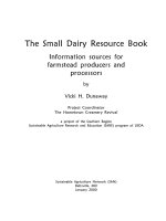
srl $13, $2, 20
andi $25, $13, 1
srl $14, $2, 21
andi $24, $14, 6
or $15, $25, $24
srl $13, $2, 22
andi $14, $13, 56
or $25, $15, $14
sll $24, $25, 2
Sequence of MIPS instructions
27 26 25 23 22 20
765432
0
. . . 0 . . .
Actual bit-level logic (wiring only)
Figure 1.1: Performance overhead of using general purpose instructions, for a bit
permutation example in DES encryption algorithm (adapted from [44]).
1.1.1 Inefficiency of General Purpose Processors
A General Purpose Processor (GPP) is mostly designed with its generality in mind,
achieved through the following sources. First, an application is broken down into
a set of most fine grained yet general operations (e.g., 32-bit integer addition). A
proper combinations of these fine grained general operations can be used to express
any sorts of computations. This set of general operations defines the interface be-
tween the software and the processor, and is referred to as the Instruction-Set Archi-
tecture (ISA). Single operations or the instructions are executed through temporal
reuse of a set of Functional Units (FU) inside the processor. Second, the sequence
of instructions (and data), referred to as the program, is stored in a separate storage
(i.e., the memory hierarchy). Each instruction is loaded and executed by the GPP
at run time through a fetch-decode-execute cycle. In this Von Neumann architec-
ture, computations can be changed simply by replacing the programs in the storage,
without modifying the underlining hardware. The programs are hence referred to
as Software due to the ultra flexibility and fluidity of realizing and switching among
different computations.
The efficiency degradation of a GPP is largely caused by the requirement to
CHAPTER 1. INTRODUCTION 4
maintain generality. First, using general purpose instructions can lead to large
performance overhead. A very good example is shown in Figure 1.1, where sparse
yet simple bit permutations need to be encoded with a long instruction sequence.
Moreover, a uniform bit length (e.g., 32-bit) of operands is under utilized in most
occasions. Second, computation on a GPP needs to be sequentialized to reuse a
handful of FUs. In this process, dependencies, from both dataflow and control
flow, slow down the performance. As an example, the sum of 3 variables needs to
be broken down into 2 consecutive 2-input additions. With the second addition
data-dependent on the result of the first one, the execution on a general purpose
2-input FU requires two cycles to finish. On the other hand, the delay of a 3-input
adder implemented directly with hardware increases only marginally. Figure 1.2
shows the block diagram of a 16-bit 3-input adder, which is composed of a layer
of full adders on top of a 16-bit 2-input carry look-ahead adder. While the 16-bit
2-input carry look-ahead adder usually involves 8 gate levels (implemented in four
4-input carry look-ahead adders with a lookahead carry unit), the full adders on
top involve only 2 gate levels. Therefore, the delay of a 16-bit 3-input adder is
increased roughly 25% compared to that of a 2-input one. For a 32-bit 3-input
adder, the relative delay increase is even less. If the clock cycle of the processor is
not constrained by the FU, as is often the case, the 3-input addition can be executed
within the same processor cycle. The sequential model of GPP execution marks the
key difference between the implementations in software and specialized hardware
1
.
Third, the energy efficiency of the instruction fetch-decode-execute cycle is quite
poor. Comparing with the energy consumed by the real computations, much more
energy is spent on the memory hierarchy and complicated mechanisms to fill the
1
Modern GPP architectures are able to exploit, to some extent, the lateral dataflow parallelism.
Superscalar processors utilize large reservation stations and wide multi-issue units; VLIW proces-
sors rely on instruction packages containing multiple parallel instructions. Both architectures are
restricted by the number of FUs that can execute concurrently, where a linear increase in number
of FUs increase the overall circuit complexity significantly. Control flow parallelism faces the same
restrictions as the dataflow part.
CHAPTER 1. INTRODUCTION 5
16-BIT CARRY LOOK-AHEAD ADDER
FA
X
15
Y
15
Z
15
C
16
S
15
B
15
FA
X
14
Y
14
Z
14
C
15
S
14
B
14
FA
X
0
Y
0
Z
0
C
1
S
0
B
0
FA
X
1
Y
1
Z
1
C
2
S
1
B
1
A
0
A
1
A
15
A
2
…
S[15:0]
0
Figure 1.2: Architecture of a 16-bit, 3-input adder (adapted from [32]).
execution pipeline (to name a few, branch prediction, out-of-order execution and
predicated execution) for sustained performance.
1.1.2 ASICs — the Extreme Specialization
As opposed to software running on a GPP, the Application-Specific Integrated Cir-
cuit (ASIC) is referred to as the Hardware implementation of the application. ASICs
hard-wire the application logic across the hardware space — a “sea of gates”. The
hardware logic can be directly derived from the application (e.g., the application
fragment in Figure 1.1 only needs simple wiring), combined for gate level optimiza-
tions and adapted to exact bit-widths. Most importantly, unlike GPPs that rely on
the reuse of FUs over time, ASICs exploit spatial parallelism offered in the hardware
space. The inherently concurrent execution model is able to exploit virtually all the
parallelism. Without the instruction fetch-decode-execute cycle, high performance
and low power consumption can be achieved simultaneously.
However, the efficiency of ASICs does come at the cost of programmability.
ASICs are totally inflexible. Once the device is fabricated, its functionalities are
fixed. Every new product, even with small differences, needs to go through a new
CHAPTER 1. INTRODUCTION 6
design and mask process
2
, which drastically increases the design time and Non-
Recurring Engineering (NRE
3
) cost. Updating existing equipments for new stan-
dards is not possible without hardware replacement. This inflexibility is especially
undesirable for small volume products with minor functional changes (e.g., different
models of cell phones in the same series), or under tight time-to-market pressure.
1.1.3 Software vs. Hardware
The differences between software and hardware are further elaborated in Table 1.1.
Table 1.2 summarizes and expands a little on the general pros and cons of using
GPPs or ASICs over common design concerns.
As we can imagine, GPPs and ASICs sit at the very two ends of the spectrum
with exactly opposite pros and cons. Either choice causes sacrifice of the benefits
from the other one. Consequently, the current industrial practice couples GPPs and
ASICs to different extents so as to take advantage of the combined strength, yielding
a spectrum of possible choices.
1.1.4 Spectrum of Specializations
Specialized circuits can be integrated to cooperate with the processor at various lev-
els. Fine grained specialization can be done at the instruction level of the processor.
In this way, frequently occurring computational patterns (which include multiple
operations) can be executed more efficiently as complex instructions in specialized
functional units directly on the processor’s datapath.
2
Mask process creates photographic molds for multi-layered IC, and is usually very expensive.
3
NRE refers to the one-time cost of researching, designing, and testing a new product, and is
supposed to be amortized in the later per-product sales.
CHAPTER 1. INTRODUCTION 7
Software Hardware
Execution model Sequential model. Concurrent model.
Logic encoding As formatted instructions in
the system memory.
As hard-coded gates on the
chip space.
Logic decoding On-the-fly by the decoding
logic in the processor pipeline.
Generated signals control the
actual function of the FU for
the instruction.
Not needed.
Logic granularity Coarse, operations being “gen-
eral” and operating on stan-
dard bit-length operands.
Fine, exact bit-level manipula-
tions and bit-length.
Execution granularity Fine, each instruction per-
forms a single operation.
Coarse, a single hardware
function packs a portion of
computations.
Table 1.1: Software vs. Hardware.
Design Concern Using GPP Using ASIC
Performance Low, due to logic overhead, in-
struction fetch and decode over-
head, and most importantly
lack of concurrency.
High, due to bit-level manip-
ulation, exact bit-width, logic
combination and optimization,
and concurrent execution.
Power consumption High, due to instruction load-
ing, pipelining with high clock
frequency, cache, out-of-order
execution, etc.
Low, no instruction overhead,
lower clocking.
NRE cost Low, given off-the-shelf GPP,
this mainly involves software
development, supported by ro-
bust and fully automated com-
pilation tools.
High, requiring intimate hard-
ware design knowledge, expen-
sive development and verifi-
cation equipments and tools,
mask cost.
Manufactory cost High, GPP system cost more
silicon than ASICs.
May cost less silicon.
Time-to-market Fast, less development time. Slow, long development and
pre-manufacturing process.
Risk Small, low NRE cost and fast
time-to-market.
Big, high NRE cost and slow
time-to-market.
Maintainability Good, software maintenance is
easier, bug fix and functional
changes can be applied easily.
Poor, any faults found after
fabrication may cause produc-
tion recall.
Table 1.2: GPP vs. ASIC