Studies of vortex breakdown and its stability in a confined cylindrical container 4
Bạn đang xem bản rút gọn của tài liệu. Xem và tải ngay bản đầy đủ của tài liệu tại đây (864.06 KB, 19 trang )
CHAPTER 4 SPIRAL VORTEX BREAKDOWN STRUCTURE
*
Part of this work has also appeared in Phys. Fluids. 17, 2005
49
CHAPTER 4
*
SPIRAL VORTEX BREAKDOWN STRUCTURE AT
HIGH ASPECT RATIO CONTAINER
4.1 Introduction
Earlier experimental studies [see Vogel, 1968 and Escudier, 1984] showed that
vortex breakdown in an enclosed cylindrical container with one rotating endwall could
exhibit either one, two or three re-circulating bubbles depending on the combination of
Reynolds number (Re) and aspect ratio (Λ), at least for Λ ≤ 3.5. However, a recent
numerical study by Serre and Bontoux (2002) at Λ = 4.0 showed that under some
conditions, an S-shape vortex structure followed by a spiral-type vortex breakdown
could also be produced. This finding is most interesting since a spiral-type vortex
breakdown in an enclosed cylindrical container has not been produced previously in
experiments. This part of the investigation is to experimentally address the following
issues: (a) Can an S-shape vortex structure and a spiral-type vortex breakdown be
produced under laboratory condition? (b) How does a bubble-type vortex breakdown,
which is known to occur only in a low aspect ratio container (Λ ≤ 3.5) evolves into an
S-shape structure and a spiral-type vortex breakdown in a high aspect ratio container
(Λ ≥ 3.5)? (c) Can a spiral-type vortex breakdown be also generated in a low aspect
ratio container if we remove the flow symmetry, as this constraint is often cited as one
of the factors responsible for the absence of a spiral-type vortex breakdown in an
enclosed container?
CHAPTER 4 SPIRAL VORTEX BREAKDOWN STRUCTURE
50
To answer these questions, we conduct experiments using the facilities which are
described below.
4.2 Experimental Setup and Procedure
It is worth noting that the test rig and the procedure for this part of the study are
slightly different with those described in Chapter 2. Here, two sets of apparatus were
used: the first one is to address questions (a) and (b) (see Fig. 4.1), and the second one
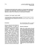
is to answer question (c) (see Fig. 4.2). The first apparatus consists of a Plexiglas
cylinder (commercial available) with a nominal inner radius R of 87.25 mm, and a
matching rotating disk at the top and a stationary disk at the bottom of the cylinder.
The height H of the flow domain, and the aspect ratio Λ = H/R, can be varied by
moving the rotating disk to a predetermined location or continuously varying the
position of the stationary disk using a micrometer, which has a maximum displacement
of 50mm or 0.573R, with an accuracy of +
0.005 mm. These unique features enable
incremental changes in the vortex structure to be studied, either by keeping the aspect
ratio constant and varying the Reynolds number or vice versa. While the former
procedure is often used by researchers, the latter method provides a more convenient
mean to observe vortex evolution at a fixed Reynolds number.
The top rotating disk was driven by an electronically controlled micro-stepper
motor operating at 20,000 steps/rev with an adjustable speed of up to 240 rpm (Ω =
25.1 rad/s), and an error of less than 0.1%. The working fluid was a mixture of
glycerin and water (about 80% of glycerin by weight) with kinematic viscosity ν =
0.401 +
0.002 cm
2
s
−1
at the room temperature of 23.5 °C. Before each run, the fluid
viscosity was measured using a Hakke Rheometer, and although the experiments were
CHAPTER 4 SPIRAL VORTEX BREAKDOWN STRUCTURE
51
conducted in an air-conditioned room, the fluid temperature was monitored regularly
using a thermocouple located at the top of the cylinder. If the temperature exceeded a
predetermined value, the experiment was stopped for the fluid to cool to the room
temperature before starting again. The cap in the temperature restricted the variation in
viscosity to less than 1%. To minimize optical distortion of flow images due to the
curvature of the cylindrical wall, the container was immersed in a rectangular box
filled with the same working fluid, since both the solution and the plexiglas have
similar refractive indices. The rectangular box also served as a constant temperature
bath for the container. To visualize the flow, food dye, which had been premixed with
the working solution, was released slowly into the flow domain through a 1.8 mm
diameter hole at the center of the bottom disk. The food dye was used as it provided a
better perspective of three-dimensional vortex structures than the laser cross-section of
fluorescent dye. In conducting the dye visualization, we were fully mindful of the
pitfalls highlighted in Hourigan et al. (1995), Lim (2000), and Sotiropoulos et al
(2002), and extra care was taken during the fabrication to ensure that various parts of
the apparatus were properly matched and the dye port is located at the centre of the
stationary disk. In all cases, the flow images were illuminated using fluorescent lamps,
and captured using a video or a still digital camera.
The second apparatus (see Fig. 4.2) is a modification of the first one, and besides
having a fixed stationary disk, a small cone was attached to either the rotating or
stationary disk at a predetermined offset position from the axis of symmetry. The cone,
which measures 60 mm in diameter and 10 mm high, serves to break the flow
symmetry by displacing the vortex filament away from the centre of the rotating disk.
Two aspect ratios were considered, namely Λ = 2 and 2.5, food dye or fluorescent dye
was used to visualize the flow.
CHAPTER 4 SPIRAL VORTEX BREAKDOWN STRUCTURE
52
4.3 Results and Discussions
4.3.1 Generation of an S-shape vortex structure and a spiral-type vortex
breakdown
Here, the first apparatus (Fig. 4.1) was used in conjunction with either one of the
following procedures, namely, (a) keeping the aspect ratio constant, while increasing
the Reynolds number or (b) keeping the Reynolds number constant, while increasing
the aspect ratio.
To validate proper working condition of the experimental setup, results obtained at
Λ = 3.5 are compared with those of Escudier (1984) as shown in Figs. 4.3 and 4.4.
Note that food dye was used in the present study for the reason cited above, as
compared to the sectional views obtained by Escudier (1984). Moreover, the present
flow images have been converted into their “negatives” to further improve their
Thermocouple
Fixed supporting disk
Square tank
R
H
Cylinder
Rotatin
g
disk
To microstepper motor
D
y
e in
j
ection
p
ort
Ball bearin
g
Offset
cone
ε
Fig. 4.1 Schematic drawing of the
first set of apparatus.
Fig. 4.2 Schematic drawing of the
second set of a
pp
aratus.
CHAPTER 4 SPIRAL VORTEX BREAKDOWN STRUCTURE
53
contrast (see Fig. 4.4). For ease of comparison, the flow visualization images of
Escudier (1984) have been rotated by 180
o
to correspond to the present setup (i.e. with
the rotating endwall at the top of the pictures). Taking into consideration that
Escudier’s results are uniformly stretched in the radial distances by 8% due to the
refraction at various interfaces, our results are in good qualitative and quantitative
agreement with his, thus indicating that our apparatus is in good working order. Small
differences in the Reynolds number (less than 0.6%) can be attributed to the sensitivity
of the function generator used to control the speed of the stepper motor and the
accuracy of the measured viscosity. From the figures, it is worth noting that the dye
filament in the two studies underwent similar “helical instability" with decreasing
wavelength prior to the onset of a bubble-type vortex breakdown. This “instability” is
a manifestation of an offset dye injection as highlighted by Hourigan et al. (1995).
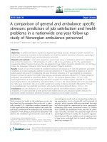
Fig. 4.3 Results of Escudier (1984) [with permission from Springer] showing the
initiation and evolution of a bubble-type vortex breakdown with increasing Re for Λ =
3.5. HI denotes a “helical instability” which is a manifestation of an offset dye
injection as highlighted by Hourigan et al. (1995).
CHAPTER 4 SPIRAL VORTEX BREAKDOWN STRUCTURE
54
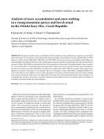
Fig. 4.4 Generation and evolution of vortex structures with increasing Re for Λ = 3.5
obtained in the present study. HI denotes “helical instability” of dye filament. Note
that the results of Escudier appear larger because the radial distances are uniformly
stretched by about 8% due to the refraction at the various interfaces. The vertical
distances of separation between the two bubbles in both Figs. 4.3 and 4.4 matched
each other.
Figure 4.5 shows the results obtained when the aspect ratio was increased to 4.0.
Here, unlike the lower aspect ratio case of Λ = 3.5, increasing the Reynolds number
did not lead to the formation of a bubble-type breakdown. Instead, when the Reynolds
number was of approximately 3061, the precessing vortex filament moved radially in a
rapid manner to give the appearance of an “S” as shown in Fig. 4.5 (c). At this stage,
no vortex breakdown was formed upstream of the S-shape vortex structure. However,
further increases in the Reynolds number eventually led to the formation of a spiral-
CHAPTER 4 SPIRAL VORTEX BREAKDOWN STRUCTURE
55
type vortex breakdown at the upstream location (see Fig. 4.5(f)). This can be deduced
from the presence of an abrupt kink in the dye filament indicating the presence of a
stagnation point which was also observed in the numerical simulations by Serre and
Bontoux (2002). Although attempts were made to conduct the experiment at higher
Reynolds number, the results were inconclusive, as flow unsteadiness caused the dye
to diffuse rapidly and made the interpretation of the flow difficult. Nevertheless, the
present results support the numerical findings by Serre and Bontoux (2002) of the
existence
of an S-shape structure and a spiral-type vortex breakdown at Λ = 4,
although the onset Reynolds numbers for both the vortex structures were lower in the
experiment. Specifically, Serre and Bontoux (2002) show that from Re = 2500 to Re =
3400, the flows are steady without breakdown, but at Re = 3500, transition to a
periodic regime takes place through an axisymmetric Hopf Bifurcation, and beyond Re
= 3500, the flows are characterized by spiral arms evolving in helical structures in the
central region of the flow. Their critical transition Reynolds number (Re = 3500) is in
good agreement with the extrapolated data of Gelfgat et al. (1996) who have earlier
highlighted the discrepancy in the critical Reynolds numbers obtained numerically and
experimentally. In the present study, the critical Reynolds number is approximately
3000, which is consistent with the Escudier’s stability diagram extrapolated to Λ = 4.0.
When the aspect ratio was reduced to 3.75 as shown in Fig 4.6, the vortex filament
evolved through some convoluted motion into an S-shape structure at the downstream
side (i.e. closer to the rotating endwall) and subsequently into a spiral-type vortex
breakdown at the upstream side (closer to the stationary endwall) at Re = 3463 (see
Fig. 4.6 (f)).
CHAPTER 4 SPIRAL VORTEX BREAKDOWN STRUCTURE
56
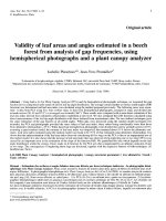
Fig. 4.5 Generation and evolution of vortex structure with increasing Re for Λ = 4.0.
Note the formation of an S-shaped structure in (c) and a spiral-type breakdown in (f).
Fig. 4.6 Generation and evolution of vortex structure with increasing Re for Λ = 3.75.
Note the formation of a helical instability in (a) and (b), S-shaped structure in (e), and
a spiral-type breakdown in (f).
CHAPTER 4 SPIRAL VORTEX BREAKDOWN STRUCTURE
57
Figure 4.7 shows the results when the aspect ratio was reduced further to Λ = 3.65.
This condition is interesting in that the vortex filament underwent three stages of
development as the Reynolds number was increased, namely a bubble-type vortex
breakdown, an S-shape vortex structure and finally a spiral-type breakdown. As
depicted in Fig. 4.7, the vortex filament between Re = 2850 and Re = 2978 eventually
led to the generation of a bubble-type vortex breakdown at the downstream side (see
Fig. 4.7(c)), with its size growing with increasing Reynolds number until Re = 3236
(see Fig. 4.7 (c) to (f)). Further increases in the Reynolds number caused the bubble-
type breakdown to slowly evolve into an S-shape vortex structure, with a spiral-type
vortex breakdown emerging upstream of it (see Figs. 4.7(g) and (h). At Re = 3275, the
precession motion of both the downstream and upstream vortex structures were clearly
displayed in the experiment, indicating that the flow was approaching an unsteady
condition. This is consistent with the experimental observations by Escudier (1984)
and the numerical simulations by Serre and Bontoux (2002). As in the case of Λ = 4.0,
the results obtained at Reynolds numbers higher than 4501 were inconclusive due to
rapid diffusion of the dye.
CHAPTER 4 SPIRAL VORTEX BREAKDOWN STRUCTURE
58
Fig. 4.7 Generation and evolution of vortex structure with increasing Re for Λ = 3.65.
Note the increasing size of the bubble-type vortex breakdown with the Reynolds
number before it disintegrated into an S-shaped structure.
Although varying the Reynolds number and keeping the aspect ratio constant has
provided valuable information on the generation of an S-shape vortex structure and the
spiral-type vortex breakdown, it gives little clue as to how a bubble-type vortex
breakdown evolves into an S-shape structure for a fixed Reynolds number. Moreover,
the acceleration/deceleration of the rotating disk due to changes in the Reynolds
number invariably leads to vorticity production at the corner between the rotating
endwall and the sidewall, and therefore more time is needed for this “starting” vortex
to diffuse and for the flow to stabilize. This motivated us to approach the problem from
a different angle, i.e. by keeping the Reynolds number fixed and increasing the aspect
ratio continuously from 3.5 to 4.0 by moving the stationary endwall using a
micrometer as shown in Fig. 4.1. Figure 4.8 shows the results obtained for Re = 3149,
CHAPTER 4 SPIRAL VORTEX BREAKDOWN STRUCTURE
59
where it can be seen that increasing the aspect ratio led to a reduction in the size of an
initially formed two bubble-type vortex breakdown, with the upstream and smaller
bubble eventually disappears. In contrast, the shrinking downstream bubble resulted in
the formation of a helical instability of increasing wavelength as the aspect ratio was
increased, until an S-shape structure was produced (see Figs. 4.8(h) and 4.8(i)). A
close-up view of the transformation of the downstream bubble-type vortex breakdown
is displayed in Fig. 4.9, where it can be clearly seen that as the bubble shrunk, it was
replaced by the helical instability which, through some convoluted motion,
transformed into an S-shape vortex structure (see Fig. 4.9(i)). This S-shape structure is
consistent with the corresponding vortex structure displayed in Fig. 4.5 (d) for the
same flow condition, but obtained through increasing the Reynolds number at a fixed
aspect ratio Λ = 4.0. It should be pointed out that all the flow images presented in Fig.
4.8 were obtained during one realization of the experiment, meaning that they were
captured as the aspect ratio was increased slowly from the start to the end of
experiment. The whole process may take as long as 60 minutes. During this period,
the total temperature rise was found to be about 0.3ºC, giving rise to the uncertainty in
the Reynolds number of about 2 %. Nevertheless, the results still reflect the sequence
of events which occur as a bubble-type vortex breakdown slowly evolves into an S-
shape vortex structure.
CHAPTER 4 SPIRAL VORTEX BREAKDOWN STRUCTURE
60
(a) (b) (c) (d) (e) (f) (g) (h) (i)
Λ = 3.500 3.548 3.606 3.641 3.652 3.687 3.733 3.836 4.000
Fig. 4.8 Evolution of vortex breakdown with increasing aspect ratio Λ for a fixed Re =
3149.
(a) (b) (c) (d) (e) (f) (g) (h) (i)
Λ = 3.500 3.548 3.606 3.641 3.652 3.687 3.733 3.836 4.000
Fig. 4.9 Close up view of the evolution of downstream vortex breakdown structure
with increasing aspect ratio Λ for a fixed Re = 3149.
CHAPTER 4 SPIRAL VORTEX BREAKDOWN STRUCTURE
61
4.3.2 Can spiral-type vortex breakdown be produced in a low aspect ratio
container?
This part of the investigation aims to see if an S-shape vortex structure or a spiral-
type vortex breakdown can be also produced in a low aspect ratio container by
removing the flow symmetry, as this condition is often cited as one of the constraints
that hinders the generation of a spiral-type vortex breakdown in low aspect ratio cases.
Experiments were conducted using the apparatus depicted in Fig. 4.2.
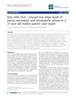
Figures 4.10 (a) and 4.10 (b) show the results obtained when the cone was at offset
positions (ε/R) of 0.05 and 0.10, respectively. Here, Λ = 2.5 and Re = 2500. The
choice of the Reynolds number was based primarily on ease of operation of the stepper
motor, as the Reynolds number was not the issue here. Part (i) of the figure shows the
broadband view of the vortex structure using food dye and part (ii) shows the
corresponding laser cross-section using fluorescent dye. As can be seen from the
broadband pictures, regardless of the cone’s offset position, a bubble-type vortex
breakdown was consistently produced, which remained stable despite their
downstream “tails” displaying a spiral trajectory. Slow motion replay of the captured
video images shows that the spiral tails were the manifestation of the dye filaments or
sheets spiraling around the periphery of the bubble-type vortex breakdown. The
absence of a spiral-type vortex breakdown was further reinforced by the corresponding
laser cross-sections depicted in Figs. 4.10 (a)ii and 4.10 (b)ii, which show close
resemblance with the results of Escudier (1984). Also, it could be seen during the
experiment that while the cone was rotating, the “tail” was gyrating about the axis of
symmetry, with the gyration increased with the cone eccentricity. Despite the three-
dimensionality of the flow field, the gyration did not seem to affect the bubble
CHAPTER 4 SPIRAL VORTEX BREAKDOWN STRUCTURE
62
geometry significantly. Although an attempt was made to increase the cone
eccentricity to above 10%, it was found to have less effect on the vortex structure
because the vortex filament reverted to the original position around the axis of
symmetry. Also, high eccentricity had the undesirable effect of magnifying the
“stirring” action, thereby hastening dye diffusion which made flow interpretation
difficult. Experiments repeated for a lower aspect ratio of Λ = 2.0 at different
Reynolds numbers were found to produce similar results.
The absence of an S-shape vortex structure or a spiral-type vortex breakdown with
the rotating cone prompted us to introduce the flow asymmetry upstream of the vortex
breakdown (i.e. on the stationary endwall). To do this, the apparatus was modified to
allow the cone to be traversed radially on the stationary endwall using a micrometer
located outside the container (figure not shown), thus allowing continuous variation of
the offset position from ε/R = 0.0 to ε/R = 0.2. In all cases, dye was introduced at the
apex of the cone through a 1.8mm diameter hole. Unlike the rotating cone, the
stationary cone has no detrimental effect on dye diffusion, regardless of the cone
eccentricity.
CHAPTER 4 SPIRAL VORTEX BREAKDOWN STRUCTURE
63
(i) Overall view
(ii) Laser cross-section
(a) ε/R = 0.05
(i) Overall view
(ii) Laser cross-section
(b) ε/R = 0.10
Fig. 4.10 Vortex breakdown generated in the presence of an eccentric rotating cone
with Λ = 2.5 and Re = 2500. (a) ε/R = 0.05. (b) ε/R = 0.10. Photographs depicted in (i)
are the negatives of the vortex structures obtained using food dye and those in (ii) are
the corresponding laser cross sections using fluorescent dye. The rotating endwall is
located at the top of each photograph, and notice how the dye filament is displayed
from the axis of symmetry of the container in the proximity of the cone.
Rotating cone
Spiral
filament
Spiral
filament
Rotating cone
CHAPTER 4 SPIRAL VORTEX BREAKDOWN STRUCTURE
64
In Fig. 4.11, changes in the vortex breakdown structures with increasing eccentricity
are displayed for Λ = 2.5 and Re = 2000. Expectedly, a symmetrical bubble-type
vortex breakdown was produced at zero eccentricity (i.e., ε/R = 0.0). However, with
ε/R increased to 0.05, the dye filament transformed drastically from the bubble-type
geometry into a spiral trajectory as can be seen in Fig. 4.11(b). Further increased in
eccentricity to ε/R = 0.10 and 0.20 produced similar results (see Figs. 4.11(c) and
4.11(d)), but with increasing wavelength. On the first glance, it appears that the vortex
structures had transformed into a spiral-type vortex breakdown, but repeated runs
showed that the spiral trajectory was merely a manifestation of an offset dye injection,
which caused the dye filament to spiral around the periphery of the distorted bubble-
type vortex breakdown. A further confirmation of this is depicted in Figs. 4.12 (a) and
4.12 (b), which were obtained at the same flow conditions as in Figs. 4.11(b) and 4.11
(d), except for the background dye introduced prior to the start of the experiment.,
which enables both the spiraling dye trajectory and the bubble geometry to be seen
simultaneously. The faintness of the bubble geometry was due to dye diffusion as it
was re-circulated in the container. The findings in Figs. 4.11 and 4.12 raise two
important issues. Firstly, they highlight the pitfall of inferring the behavior of vortex
filament from the dye filament, if the dye is not introduced directly into the vortex
core. This is the point highlighted by Hourigan et al. (1995) and Lim (2000). Second,
they show that a bubble-type vortex breakdown is highly stable in a low aspect ratio
container, and disrupting the flow symmetry merely distorts the bubble geometry
without it transforming into a spiral-type vortex breakdown as can be seen in the laser
cross-sections displayed in Fig. 4.13, which correspond to the broadband picture in
Fig. 4.11. Similar results were obtained when the experiments were conducted at
higher Reynolds numbers and lower aspect ratio (i.e. Λ = 2.0).
CHAPTER 4 SPIRAL VORTEX BREAKDOWN STRUCTURE
65
Fig. 4.11 Vortex structures obtained using different eccentricity of the cone on the base
plate with Λ = 2.5 and Re = 2000. Sequence (a)-(d) show the effect of increasing
eccentricity. These pictures are the negatives of the original pictures captured using
food dye released from the apex of the cone. The rotating endwall is located at the top
of each picture, and the cone is at the stationary bottom wall.
Fig. 4.12 Vortex structures obtained using identical flow conditions as in Figs 4.11(b)
and 4.11(d). Here, some background dye has been introduced in the flow domain prior
to the experiment. These pictures clearly show the presence of a bubble-type vortex
breakdown. Note how the dye filament in each picture spirals around the peripheral of
the vortex breakdown.
CHAPTER 4 SPIRAL VORTEX BREAKDOWN STRUCTURE
66
Fig. 4.13 Laser cross sections of the vortex structures generated using identical flow
conditions as in Fig 4.11, Λ = 2.5 and Re = 2000. The pictures were captured using
laser induced fluorescent dye illuminated with a thin laser sheet. The distortion of the
vortex breakdown with increasing eccentricity can be seen in (c) and (d).
4.4 Concluding Remarks
The aim of the present investigation is to address the three issues raised in the
introduction, and all the questions have been answered. Our experiments confirm the
existence of an S-shape vortex structure and a spiral-type vortex breakdown, not only
for Λ = 4.0 as was first observed in the numerical studies of Serre and Bontoux (2002),
but also for Λ as low as 3.65. Also, it is found that as a bubble-type vortex breakdown
evolves into an S-shape vortex structure as the aspect ratio is increased for a fixed
Reynolds number, there is an initial increase in the wavelength of the helical
instability, follows by the vortex filament undergoing convoluted motion before
transforming into the S-shape vortex structure and then a spiral-type vortex
breakdown.
CHAPTER 4 SPIRAL VORTEX BREAKDOWN STRUCTURE
67
The results further show that a bubble-type vortex breakdown in a low aspect ratio
container is extremely robust and introducing flow asymmetry merely distorts the
bubble geometry without it transforming into an S-shape vortex structure or a spiral-
type vortex breakdown.