Study on ingan gan quantum structures and their applications in semiconductor saturable absorber mirror 1
Bạn đang xem bản rút gọn của tài liệu. Xem và tải ngay bản đầy đủ của tài liệu tại đây (498.47 KB, 37 trang )
Chapter 1 Introduction
1
Chapter 1
Introduction
III-nitride materials including gallium nitride (GaN), indium nitride (InN),
aluminum nitride (AlN), their ternary (InGaN, AlGaN and AlInN) and quaternary alloys
(AlGaInN), are wide-bandgap III-V compound semiconductors. During the last two
decades or so, III-nitride semiconductor material system has attracted considerable
attention due to their unique and excellent optical, electrical and material properties as
compared with the conventional III-V compound semiconductors, such as III-arsenides
and III-phosphides. The highly promising applications of III-nitrides include optical
storage, laser printing, high brightness & general illumination, and wireless base
stations. Section 1.1 will highlight the currently most important applications of
GaN-based III-nitrides; and Section 1.2 will review the research development of GaN
and related III-nitride materials. Typically, the growth techniques and the major
properties of InGaN/GaN quantum wells and quantum dots will be discussed in Section
1.3. In this work, the GaN-based quantum structures will be applied in the fabrication
of saturable absorbers and semiconductor saturable absorber mirrors (SESAMs)
Chapter 1 Introduction
2
operating in the blue region. Thus, Section 1.4 will outline the essential theories of the
saturable absorber and the SESAM, and provide an overview of the development of
passive mode-locking by SESAMs.
1.1 Current applications of GaN-based III-nitrides
In this session, the currently most important applications of GaN-based
III-nitrides, including the short-wavelength optoelectronic devices [Akasaki1991;
Nakamura1995] and the high-power high-frequency high-temperature electronic
devices [Khan1993; Pearton2000; Mishra2002; Zhang2002], will be discussed.
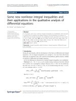
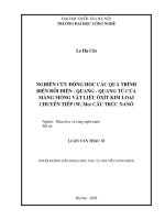
Figure 1.1 Bandgap versus lattice constant of wurtzite III-nitrides at room
temperature
Chapter 1 Introduction
3
The great potential of GaN-based III-nitrides in fabricating short-wavelength
optoelectronic devices is mainly owing to their wide range of bandgaps, which spans
from the infrared spectrum and extends well into the ultra-violet (UV). As shown in
Figure 1.1, the wurtzite polytypes of GaN, AlN and InN form a continuous alloy system
whose bandgaps range from ~ 0.7 eV for InN, to 3.4 eV for GaN and to 6.2 eV for AlN
[Nakamura1995]. Furthermore, all the wurtzite III-nitrides have direct bandgaps, which
are essential for producing light radiation efficiently. The above features enable the
III-nitrides to be good candidates for light emitting diodes (LEDs), laser diodes (LDs),
and detectors operating in green, blue and UV wavelength regions [Nakamura2000;
Akisaki2007], which are essential for developing full-color displays and coherent
short-wavelength sources required by high density optical storage technologies.
[Pearton2000]
In recent years, the introduction of GaN-based bright blue LEDs have paved
the way for full color displays and raised the probability of mixing primary colors - red,
green and blue - to obtain white light sources for illumination. Most excitingly, when
used in place of incandescent light bulbs, these GaN-based blue LEDs can provide
higher brightness and longer lifetime while consuming only ~ 10 - 20% of the power
for the same luminous flux. [Mahammad1995] Therefore, GaN-based III-nitride LEDs
have immense potentials as the candidates of the next-generation illuminating source.
Additionally, the strong absorption coefficient (4×10
4
cm
-1
) of GaN at
wavelengths shorter than 365 nm makes it also a good candidate for visible-blind UV
photodiodes. [Yagi2000] Extension of the photodiode spectral range from UV to visible
Chapter 1 Introduction
4
can be achieved by the employment of an InGaN active layer with a high In
composition (up to 67%). Furthermore, the integration of the efficient UV/blue
semiconductor light sources and the visible-blind photodiodes on a single chip has been
realized. [Pauchard2000] In the last few years, various types of GaN-based sensors
have been demonstrated, such as p-n junction diodes, Schottky diodes, and
metal-semiconductor-metal photodiodes. [Razeghi1996; Li2003; Chang2007; Yam2007]
These structures can be used for several sensor applications, such as lifetime sensors,
drug testing sensors and portable fluorescence sensors.
Besides the potential for fabricating short-wavelength optoelectronic devices,
GaN-based III-nitrides are very suitable for high-frequency electronic devices,
especially for high-power and high-temperature applications. The material properties
associated with high-temperature, high-power, and high-frequency applications of GaN
and several conventional semiconductors are summarized in Table 1.1 [Pearton2000].
As shown in the Table, compared with the conventional III-V semiconductors, GaN
with wide bandgaps can operate at much higher temperatures before going intrinsic or
suffering from thermally generated leakage current. GaN also has a higher breakdown
field of around 4 × 10
6
V cm
-1
(V
br
∝ E
g
3/2
), i.e., the maximum internal electric field
strength before the onset of junction breakdown. This allows GaN to operate as
high-power amplifiers, switches, or diodes. In addition, the good electron transport
characteristics of GaN, including extremely high peak velocity (3 × 10
7
cm s
-1
) and
saturation velocity (1.5 × 10
7
cm s
-1
), allow it to operate at higher frequencies than its
conventional cousins [Khan1995].
Chapter 1 Introduction
5
Table 1.1 Comparison of material properties of GaN, 4H-SiC, GaAs and Si
(Pearton2000)
GaN 4H-SiC GaAs Si
Bandgap E
g
at 300K (eV)
3.40 3.26 1.42 1.12
Dielectric constant
ε
9.0 9.7 12.8 11.8
Breakdown field E
B
(MV/cm)
4.0 3.0 0.4 0.25
High-field Peak velocity
ν
s
(10
7
cm/s)
3.0 2.0 2.0 1.0
Electron mobility
μ
(cm
2
V
-1
s
-1
)
1350 800 6000 1300
Thermal conductivity
χ
(W K
-1
cm
-1
)
1.3 4.9 0.5 1.5
Melting point (°C) 2791
Sublimes
T>1827
1238 1412
JFOM
*
= E
B
ν
s
/ 2π
48 24 3.2 1
BFOM
**
=
χ
μ
E
B
3
3686 3473 6.3 1
CFOM
***
=
χ
ε
μ
ν
s
E
B
2
489 458 8 1
*
JFOM: Johnson’s figure of merit for power-frequency performance of discrete
devices.
**
BFOM: Baliga’s figure of merit for power loss at high frequency.
***
CFOM: Combined figure of merit for high power/high frequency/high temperature
applications
(All figures of merit are normalized to Si)
Arising from the superior optical, electrical and material properties,
GaN-based III-nitrides have tremendous application potential in a variety of areas,
including power conditioning, wireless broadband, automotive electronics, power
transmission, telecomm base stations, satellite electronics, white solid-state lighting,
color signs & lighting, automotive lighting, high-density optical storage, pressure
sensing, heat sensing, and flame sensing. [Mills2002] The rapid development of
III-nitrides in the last two decades, which will be presented in detail in Section 1.2, can
be considered as a breakthrough in the field of wide bandgap compound semiconductor
Chapter 1 Introduction
6
materials and devices. [Pearton1999; Jain 2000; Akasaki2007]
1.2 Research development of GaN and related
III-nitride materials
The earliest attempts to synthesize GaN materials were initiated more than 70
years ago. In 1932, GaN was synthesized in the powder form [Johnson1932]; and in
1938 small needles of GaN were obtained by Juza and Hahn [Juza1938]. However, at
this early stage, the growth of high quality epitaxial nitrides was impossible and the
difficulty in controlling their conductivity had also prevented the development of
nitride-based devices. In 1969, the deposition of large-area single crystal GaN was
successfully demonstrated on a sapphire substrate by hydride vapor phase epitaxy
(HVPE). [Maruska1969]. Two years later, GaN was grown epitaxially via metal organic
chemical vapor deposition (MOCVD) and in 1974 by molecular beam epitaxy (MBE).
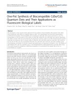
Since then, GaN-based III-nitrides have experienced rapid development over the past
few decades, as shown in Fig. 1.2.
Chapter 1 Introduction
7
Figure 1.2 Number of publications (INSPEC) and activities related to GaN-based
III-nitrides over the years
The achievement of large area GaN fabrication soon led to the first
demonstration of a III-nitride LED. [Pankove1972] This LED was a
metal/insulating-GaN:Zn/n-GaN (M-i-n or MIS) type diode. Zn was doped into GaN to
produce i-n junctions, as well as acting as the luminescence centers. The M-i-n LED
could emit blue, green, yellow or red light depending on the Zn concentration in the
light-emitting region. A year later, the Mg-doped M-i-n type diode emitting violet light
was also demonstrated [Maruska1973].
Chapter 1 Introduction
8
However, until the late 1970s, it was still quite difficult to grow high quality
epitaxial GaN film with a flat surface and free of cracks. Moreover, the conductivity of
the GaN thin film could not be controlled. All early GaN samples were n-type
conducting even without intentional doping. It was therefore impossible to produce
p-type conduction or to control the conductivity of the n-type nitrides.
In early 1980s, the above situation was drastically changed by two critical
breakthroughs, i.e. the development of the two-step growth method and the discovery
of p-type conduction. The idea of the two-step growth is, at a low temperature, to insert
a very thin buffer layer with physical properties similar to both the GaN epilayer and
the sapphire, so as to accommodate the large lattice and thermal mismatches between
GaN and sapphire. In 1983, the two-step method was first applied in the MBE growth
of GaN [Yoshida1983]. The electrical and luminescent properties of the GaN epitaxial
films were improved with a low-temperature (LT) AlN buffer on the sapphire substrate.
Later, in 1986, the world’s first high-quality GaN grown by MOCVD was also
demonstrated with a LT AlN buffer; and the optimized thickness and deposition
temperature for the LT AlN buffer were established. [Amano1986] It was later found
that a thin GaN layer could also be used as the LT buffer to obtain high-quality GaN
epilayers grown on sapphire substrates. [Nakamura1991] Moreover, besides the single
AlN or GaN LT buffer, namely single-layered buffer (SLB), a new structure for the LT
buffer, namely double-layered buffer (DLB), was also proposed later [Turnbull1996].
With this two-step growth method, the residual donor density in the GaN grown by
MOCVD decreased to the order of 10
15
cm
-3
; and the electron mobility increased by
Chapter 1 Introduction
9
more than an order of magnitude. As a result, the development of the two-step growth
technique has greatly improved not only the crystalline quality but also the optical and
electrical properties of GaN epilayers grown by MOCVD.
The second breakthrough of p-type conductivity realization in GaN was not
demonstrated until the late 1980s. With the two-step growth method, the control of the
n-type conductivity of GaN by SiH
4
doping was possible [Nakamura1992
1
]; while to
fabricate the practical LED and LD devices, the ability to control the p-type
conductivity was also necessary. Therefore, right after the first breakthrough, many
research groups attempted to produce p-type GaN with Be, Mg, or Cd doping. In 1988,
Amano et al. found that low-energy electron-beam irradiation (LEEBI) treatment
largely enhanced the blue emission of Zn-doped GaN, but the crystal still did not show
p-type conductivity. [Amano1988]. This finding suggested that the LEEBI treatment
might be closely related with the activation of Zn-acceptors. Hence, in 1989, the
Mg-doping using Cp
2
Mg or MCP
2
Mg as a Mg-dopant was successfully achieved while
the high crystal quality of the GaN was maintained. Then after the electron beam
irradiation, the Mg-doped GaN samples showed greatly enhanced blue luminescence as
well as the p-type conductivity with low resistivity. [Amano1989] This critical
discovery immediately led to the fabrication of the first GaN-based p-n junction
blue/UV LED in 1989. [Amano1989] In 1992, p-type GaN was also produced by
annealing GaN:Mg at above 700
o
C in N
2
or vacuum ambient. [Nakamura1992] A hole
concentration as high as 3×10
18
cm
-3
was achieved with a resistivity of only 0.2 Ω⋅cm.
Compared to the LEEBI treatment method, this annealing method is a more effective
Chapter 1 Introduction
10
way to achieve p-type conduction and more favorable for mass-production. Afterwards,
p-type GaN was also obtained by UV or electro-magnetic wave irradiation at
temperatures below 400
o
C. [Kamiura1998; Tsai2000; Takeya2001]
The activation of the Mg acceptors by either the beam radiation or the N
2
annealing is related to the hydrogen passivation effect. [Nakamura1992
2
] It has also
been found that the p-type conductivity is dominated by the acceptors with an
activation energy of ~170 meV; and these acceptors are attributed to the Mg atoms
substituting for Ga atoms in the GaN lattice. [Gotz1996] Due to the high ionization
energy of Mg, the acceptor activation ratio is typically in the range of 0.1% to 1%.
Therefore, a high Mg chemical concentration, in the range of ~10
20
cm
-3
,
has to be
incorporated to achieve a good p-type conducting GaN epilayer. Up to now, Mg is the
only effective acceptor successfully developed for III-nitrides.
As shown in Fig. 1.2, the above-mentioned two critical breakthroughs
(two-step growth method and p-type conductivity control) have eventually led to the
commercialization of high-brightness blue LEDs and long-life blue-violet LDs as well
as the development of a large variety of III-nitride based optoelectronic devices. To
fabricate the devices with longer lifetimes, epitaxially lateral overgrown (ELO) GaN on
sapphire was then developed to largely reduce the threading dislocations.
[Kapolnek1997; Nam1997] Additionally, to further eliminate the effects of sapphire,
pure GaN substrates, fabricated by removing the sapphire substrate after the growth of
thick GaN layers on the ELO GaN template, were even fabricated for the growth of
GaN-based epilayers. [Nakamura1998] Furthermore, in order to further improve the
Chapter 1 Introduction
11
performance of these devices and explore their applications at different wavelengths,
the alloys of III-nitrides have to be applied. The InGaN, a ternary alloy of GaN and InN,
is a good candidate for fabricating optoelectronic devices operating in the blue to green
wavelength regions. Section 1.3 will briefly summarize the growth techniques as well
as the major properties of the InGaN quantum structures, including InGaN/GaN
quantum wells and InGaN quantum dots.
1.3 InGaN/GaN quantum wells and quantum dots
InGaN is an important alloy for fabricating III-nitride optoelectronic devices.
First of all, its bandgap energy can be continuously varied from 0.7 to 3.4 eV
(corresponding to the emission spectrum from infrared to near UV) by adjusting the In
composition. Additionally, InGaN demonstrates much higher luminescence efficiency
than GaN or AlGaN. [Mukai1998] Furthermore, InGaN can easily form
hetero-structures with other III-nitrides, such as GaN, AlGaN or InGaN with different
In compositions. [Unlu2002]
To fabricate reliable optoelectronic devices, the InGaN films have to be grown
with high crystal quality. Because of the low miscibility of InN in the GaN, the InGaN
should be grown at low temperatures to prevent the InN dissociation. However, a low
temperature would then lead to poor crystal quality. Hence, it is very difficult to
discover the optimal growth conditions for InGaN. Initially, researchers attempted to
growth InGaN films at about 500
o
C, but without success. In 1991, Yoshimoto et al.
reported the growth of InGaN single-crystal films on (0001)-oriented sapphire at 800
o
C
Chapter 1 Introduction
12
by MOCVD. [Yoshimoto1991] Owing to the relatively high growth temperature, strong
band-edge photoluminescence was observed at 77K. However, such a InGaN film still
suffered from the strong deep-level emissions at room temperature; and the full width at
half maximum (FWHM) of the double-crystal X-ray rocking curve (XRC) for (0002)
diffraction from the InGaN films was as broad as 30 minutes. The breakthrough of the
growth of high quality InGaN was soon achieved in 1992 by Nakamura et al. in Nichia
Chemicals. At the growth temperature between 780
o
C to 830
o
C, high-quality InGaN
single crystal layer was successfully grown with their unique two-flow MOCVD
system. [Nakamura1992
3
] This breakthrough soon led to the fabrication of the
hetero-structure InGaN/GaN LED in 1993 [Nakamura1993] and the first
commercialized candela-class InGaN hetero-structure blue LED in 1994
[Nakamura1994].
Up to now, InGaN/GaN quantum wells have been widely investigated and
epitaxially grown on the highly dissimilar sapphire substrates. Because of the 30%
lattice mismatch between GaN and sapphire, one would expect that the existence of a
large number of threading dislocations should make the light emission from such
quantum wells almost impossible. However, surprisingly, experimental results have
shown that the emission intensity of the InGaN/GaN quantum wells is not significantly
dependent on the dislocation density. As a result, high brightness LEDs and
continuous-wave blue-violet LDs based on InGaN quantum well structures have been
successfully demonstrated with high performance and high quantum efficiency.
[Kim2002; Martin2002]
Chapter 1 Introduction
13
As the InGaN quantum wells exhibit highly unusual optical properties, many
efforts have been made in the past decade to investigate the underlying mechanisms.
These findings, however, have pointed to a general lack of consensus. Initially, it was
proposed that the carrier localization in potential variations, caused by alloy
fluctuations and/or phase separation, prohibited the non-radiative recombination of the
excitons at the threading dislocations. [Nakamura1998
1
; O’Donnell2001] This
explanation was supported by the transmission electron microscope (TEM) images
showing the small dot-like structures. [Narukawa1997] However, recently, a detailed
TEM study indicates that such dot-like structures may be artifacts due to the radiation
damage during the TEM observation. [Smeeton2004]
Considering the lattice mismatch between the InGaN and GaN, it has also
been argued that, the large built-in internal electric field inside the quantum wells,
caused by spontaneous polarization and strain-induced piezoelectric polarization, might
play an important role in the unusual optical properties of InGaN quantum wells.
[Bernardini1997] It was suggested that, such a huge internal field, in the order of
MV/cm, would give rise to a strong “quantum confined Stark effect” (QCSE), resulting
in a strong red shift of the emission. [Takeuchi1997] In addition, the electric field could
also lead to a dramatic reduction in the oscillator strength. [Im1998] However, it was
then pointed out that, according to the above theory, an even smaller efficiency due to
the reduced oscillator strength should be expected.
More recently, by applying the spectroscopic scanning near-field optical
microscopy on different InGaN/GaN quantum well samples, Hangleiter et al. proposed
Chapter 1 Introduction
14
that, the hexagonal V-shaped pits decorating the defects exhibit narrower sidewall
quantum wells with an effective bandgap significantly larger than that of the regular
c-plane quantum wells. [Hangleiter2005] Hence, such a higher bandgap surrounding
each defect might form a natural energy barrier, which keeps carriers from reaching the
defects and recombining non-radiatively. [Hitzel2004]
While InGaN quantum wells have been widely applied in fabricating
short-wavelength optoelectronic devices, InGaN quantum dots are also ideal arenas for
exploring the physics of low-dimensional structures. Owing to the three-dimensional
(3D) confinement effect of the carriers, considerably lower threshold current density,
narrower spectral linewidths, higher brightness, higher direct modulation speed and
better temperature stability are expected for quantum dot lasers. [Arakawa1982;
Asada1986; Arakawa2001]
In order to achieve good device performance, formation of quantum dots with
high density, high crystal quality, and good uniformity on the atomic scale is required.
Generally, quantum dots can be formed by two methods: one is the selective growth
and the other is the self-assembly growth. For the selective growth method, the
nanometer-scale lateral structures can be artificially created with the advanced
lithography techniques, such as x-ray nanolithography, e-beam lithography and
nano-imprinting. The quantum dot structures can then be fabricated by selected crystal
growth on the above patterned substrates. [Wang1999; Tachibana2002; Martin2005]
However, quantum dots formed by this method suffered from structural problems. For
example, the microstructures were too large to produce quantum effects; and the crystal
Chapter 1 Introduction
15
quality of the microstructures was relatively low at the interfaces. The self-assembly
growth utilizes strain as the driving force to fabricate the coherent 3D quantum
structures in the MBE or MOCVD growth [Ledentsov1997]. As a result, high-quality
quantum dots suitable for making optoelectronic devices can be fabricated using this
approach [Ledentsov2000, Borovitskaya2002].
Because of the superior advantages of the self-assembly growth method,
several groups have fabricated InGaN quantum dots based on this method. Hirayama et
al. used Si as the anti-surfactant to grow self-assembled InGaN quantum dots on
AlGaN surface with MOCVD. InGaN quantum dots with a high density of ~ 10
11
cm
-2
showed the average diameter and height of ~ 10 nm and ~ 5 nm, respectively.
[Hirayama1998] Tachibana et al. fabricated self-assembled InGaN quantum dots
without any surfactant, using atmospheric pressure MOCVD. The average diameter and
height of these quantum dots were 8.4 nm and 2.1 nm, respectively, with the density
from 2.1×10
10
cm
-2
to 4.5×10
9
cm
-2
depending on the growth temperature.
[Tachibana1999] Moreover, lasing oscillation was achieved with a 10-stacked InGaN
quantum dot laser by optical pumping [Tachibana1999
1
]. Also following the
Stranski–Krastanow (S-K) growth mode, Adelmann et al. fabricated self-assembled
InGaN quantum dots using MBE. The size of the quantum dots was typically 27 nm
wide and 2.9 nm high, with a density of ~ 9×10
10
cm
-2
. [Adelmann2000] By applying
surface passivation and low temperature growth, Chen et al. successfully demonstrated
multi-sheet InGaN quantum dots using MOCVD. The quantum dots were about
40-nm-wide and 15-nm-high with a density of 6.3×10
10
cm
-2
in the first layer and grew
Chapter 1 Introduction
16
bigger in upper layers. [Chen2002; Chen2002
1
] More recently, high-density InGaN
nanodots were fabricated in our group by Chen et al. on SiO
2
pretreated GaN surfaces,
using MOCVD. The InGaN nanodots were 26-68 nm in diameter, 3.6-15 nm in height,
and up to 9×10
10
cm
-2
in density, which can be controlled by growth duration and
substrate temperature. [Chen2006]
1.4 Saturable absorber and semiconductor saturable
absorber mirror (SESAM)
Over the past few years, progress in the research on ultrafast lasers has
enabled the increased applications of these lasers in the areas such as physics,
chemistry, biology and medicine. Most applications of ultrafast lasers can be grouped
into four different categories which benefit from different properties of such lasers.
First of all, in the time domain, the ultra-short pulses provide excellent time resolution
in characterizations; second, the relatively high peak power at the low average power is
crucial to reduce thermal effects in material processing; third, the short coherence
length at high average power improves the signal to noise ratio in measurements; fourth,
the broad coherent spectrum can be filtered to obtain different pulse sequences.
[Keller1996]
The first significant step towards short laser pulses was Q-switching, which
generated laser pulses of ~ 10
-8
second duration. [McClung1962] A few years later, a
new technique called “mode-locking” was introduced; and laser pulses shorter than 10
-9
second were then generated. [Fork1964; Mocker1965; DeMaria1966] Up to now,
Chapter 1 Introduction
17
femtosecond (fs or 10
-15
second) pulses have successfully been generated from those
mode-locked lasers. [Jung1997
1
; Sutter1999; Schön2002; Kowalevicz2002;
Nielsen2005; McFerran 2007]
The aim of the mode-locking technique is to force the different modes to be
in-phase. Consequently, the laser output would be a result of constructive interferences
of coherent modes, and therefore contains periodic, high power, short duration optical
pulses. There are mainly two methods for achieving mode-locking, i.e. active
mode-locking and passive mode-locking. Compared with the active mode-locking
scheme, which requires external modulation as well as external energy consumption,
the passive scheme is usually simpler and can occur in a much faster time scale.
Therefore, different types of passive mode-locking have been explored, such as additive
pulse mode-locking (APM) [Stalder1992], Kerr lens mode-locking (KLM) [Asaki1993]
and semiconductor saturable absorber mode-locking [Keller1992]. Among these
techniques, passive mode-locking by a saturable absorber is the most effective
technique, which simplifies the mode-locking procedures and makes the lasers compact
and inexpensive. Section 1.4.1 will outline the basic concept of a saturable absorber,
and the key properties of a semiconductor saturable absorber mirror (SESAM) will be
presented in Section 1.4.2. To provide an overall background, Section 1.4.3 will be
devoted to a literature review on the passive mode-locking by SESAMs.
1.4.1 Basic concept of a saturable absorber
A saturable absorber is a material in which the light transmittance increases
Chapter 1 Introduction
18
nonlinearly with the incident light intensity. In other words, it has lower loss for higher
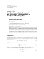
pulse intensities or energies, and vice versa. The physical mechanisms of a
semiconductor absorber are expressed in Fig.1.3. A semiconductor can absorb light if
the photon energy is sufficient to excite carriers from the valence band to the
conduction band. Then under conditions of strong excitation, the absorption can be
saturated, because the initial states of the absorbing transition are emptied or the final
states are occupied. As a result of the absorption saturation, the light can pass the
absorber without being absorbed, meaning that the absorber becomes “transparent”.
Subsequently, within a short time after the excitation, i.e. typically after 60 - 300 fs, the
carriers in each band thermalize, leading to a partial recovery of the absorption. Then,
on a longer time scale, i.e. typically between a few picoseconds (ps) and a few
nanoseconds (ns), those carriers are recovered by recombination and trapping. The
above two processes can both be used for the mode-locking of lasers. [Fermann2003]
Figure 1.3 Physical mechanism of a semiconductor saturable absorber
Based on a two-level model, the absorption coefficient of a saturable absorber
changes with the incident light intensity I
i
as follows [Rulliére1998]:
1
0
)1()(
−
+=
sat
i
i
I
I
I
αα
(1.1)
where
0
α
is the low-intensity (linear) absorption coefficient. is the saturation satI
ħω
0
E
2
, n
2
E
2
, n
2
ħω
0
ħω
0
E
1
, n
1
E
1
, n
1
Chapter 1 Introduction
19
intensity, which is the incident light intensity necessary to decrease
α
to a half of its
value at the low incident light intensity (i.e.
2/0
α
α
=
at sati II
=
). This nonlinear
relationship between the absorption coefficient and the incident light intensity is shown
in Fig. 1.4.
Figure 1.4 Absorption as a function of incident a saturable absorber
In addition, by using the Beer-Lam
light intensity for
bert law,
II it )Lexp(
α
−
=
, the transmittance
T of a saturable absorber can be expressed as [Rulliére1998]:
)
/
1 sati III +
exp()(
t
i
I
IT
0
i
L
−
==
α
,
tI is the tr
is also sketched in Fig. 1
(
ansm
.5.
1.2)
where L is the length of absorbing medium and itted light intensity.
This nonlinear transmission behavior
Chapter 1 Introduction
20
Figure 1.5 Transmission as a function of incident light intensity for a saturable
absorber
As can be observed in Fig. 1.5, at low I
i
, T
≈
T
0,
which is almost independent
of I
i.
When I
i
increases, the population of the upper level involved in absorption
increases, and the population of the lower level decreases. Hence, the combination of
these two effects leads to a nonlinear behavior of T (I
i
). When I
i
is further increased to
the high intensity, the absorber is saturated and becomes transparent (T=1); it is
eventually “bleached”.
Owing to the nonlinear property of a saturable absorber, it can be used in
passive mode-locking for short pulse generation. The schematic setup of mode-locking
by a saturable absorber is shown in Fig. 1.6. The mode-locking process in the time
domain can be described as follows. In a multimode laser, the output is the incoherent
interference of random modes, resulting in the temporal fluctuations of light intensity
inside the cavity. (Fig. 1.7 (a)) When some strong noise spikes appear, they experience
less loss compared to the weaker noises when traveling through a saturable absorber,
due to the nonlinearity of the absorber. Then the intensities of those spikes increase
Chapter 1 Introduction
21
much faster than the background noises. (Fig. 1.7 (b)) Finally, after a few round-trips,
one dominant spike contains a significant part of the circulating energy because it
experiences the lowest absorption, while other background noises decay quickly. (Fig.
1.7 (c))
Figure 1.6 Schematic setup for passive mode-locking using a saturable absorber
[Xiang2003]
Figure 1.7 Evolution of a short pulse during the mode-locking by a saturable absorber.
(a) Low intensity regime (
sati
II < ), with random fluctuations; (b) , the onset
of the discrimination of the weak peaks; (c) Final energy distribution. [Xiang2003]
I
sat
I
sat
I
sat
sati
II ≈
Chapter 1 Introduction
22
ading edge and the tail of the pulse,
which ha
Fig. 1.8 (b). In the application in ultra-short optics, most absorbers
are slow absorbers, because their recovery times (nanoseconds to picoseconds) are
usually longer than the pulses generated (in the duration of picoseconds or
sub-picoseconds).
There are two ways to describe the changes of the pulse shape in a
mode-locked laser with a saturable absorber, depending on whether the recovery time
of the absorber is faster or slower than the pulse duration.
A fast absorber has the recovery time shorter than the pulse duration. As it can
respond immediately to the input intensity, the le
ve relatively lower intensities, should experience more absorption than the
peak of the pulse. Thus, as shown in Fig. 1.8 (a), a pulse experiences temporal
narrowing when passing through a fast absorber.
On the contrary, if the absorber recovers in a longer time scale compared to
the pulse duration, it is called a slow absorber. A slow absorber is normally bleached by
the leading edge of the pulse, and the later arriving part cannot experience effective
absorption. Thus, only the pulse front gets shortened, leading to an asymmetric pulse
shape as shown in
Chapter 1 Introduction
23
pulse modified by
pulse modified by
leading
edge
Figure 1.8 Illustration of pulse modification by saturable absorbers. The pulses
modified
compari
a fast absorber
a slow absorber
(a)
(b)
by the absorbers have been normalized to the original ones for easier
son. (a) Fast saturable absorber. The pulse is temporally narrowed. (b) Slow
bsorber. Only the pulse front gets shortened. [Xiang2003]
In addition, it should be noted that the amplifying medium has gain saturation
characteristics, which can make the leading part of the pulse experience stronger gain
than the rear of the pulse. Thus, the combined effects of the slow absorber and the
saturable amplifying medium on the pulse shortening can be sketched qualitatively as
shown in Fig.1.9. [Xiang2003] After many round-trips, the pulse is effectively
narrowed and the peak intensity is greatly enhanced. The shortened pulse can be
symmetrical or asymmetrical, depending on the relative effectiveness of the above two
effects.
a
Chapter 1 Introduction
24
Figure 1.9 Pulse shortened by a simultaneous action of a saturable absorber and an
amplifying medium [Xiang2003]
The development of semiconductor technology has made it possible to use
semiconductors as absorbers operating in a broad range of wavelengths and to
accurately control the device parameters, such as operation wavelength, saturation
energy, and recovery time. Compared with the bulk semiconductors, quantum well
structures are more favorable to be used as saturable absorbers, because of the
convenience to control the wavelengths and their enhanced nonlinear property. To
achieve the effective pulse shaping, the saturable absorption of a saturable absorber
should recover to its initial state in a short time (a few picoseconds to a few tens of
picoseconds). However, the absorption recovery times of those epitaxially grown
compound semiconductor quantum wells normally fall in the nanosecond range.
Therefore, many methods have been developed to purposely reduce the recovery times
of the saturable absorbers. The most common methods are low-temperature (LT)
Chapter 1 Introduction
25
1.4.2 Key properties of a SESAM
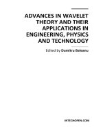
A SESAM integrates the semiconductor saturable absorber with a mirror.
More specifically, as shown in Fig. 1.6, if a semiconductor saturable absorber and the
mirror on the right side are fabricated as a single structure, this structure is called as a
SESAM. For distributed
Bragg reflector (DBR). The general structure of a SESAM using DBR is plotted
schematically in Fig. 1.10. The barriers between the quantum wells, the cap layer, and
the spacers are all transparent at the operation wavelength of the SESAM. If the
incident light has a longer wavelength than that of the absorption edge of the absorber,
it will pass through the absorber and be bounced back to the air by the DBR without
any significant absorption. But the light at a proper wavelength will be absorbed. The
absorption is saturated for high-intensity light, because electrons in the valance band
on. [Xiang2003]
growth [Gupta1992], ion implantation [Delpon1998], and proton bombardment
[Gopinath2001]. The gist of these methods is to introduce deep levels in the bandgap of
the active layer so as to reduce the carrier lifetime through the enhanced non-radiative
recombination.
a SESAM, the mirror can either be a metallic mirror or a
are exhausted, due to the absorpti
Figure 1.10 Schematic structure of a SESAM [Xiang2003]