Study on ingan gan quantum structures and their applications in semiconductor saturable absorber mirror 2
Bạn đang xem bản rút gọn của tài liệu. Xem và tải ngay bản đầy đủ của tài liệu tại đây (962.89 KB, 40 trang )
Chapter 2
Growth and Characterizations
Chapter 2
Growth and Characterizations
In this work, the GaN-based quantum wells and quantum dots were all
grown by an EMCORE D125 metal organic chemical vapor deposition (MOCVD)
system. Section 2.1 will present the essential theories of this growth technique and
highlight the major components of our MOCVD system. To fabricate a broadband
GaN-based SESAM, the SiO2/Si3N4 dielectric DBR was deposited by the plasma
enhanced chemical vapor deposition (PECVD) system. The principle of the PECVD
technique will be presented in Section 2.2. Section 2.3 will be devoted to the primary
characterization techniques used in this work, including photoluminescence (PL)
(Section 2.3.1), spectrophotometry (Section 2.3.2), atomic force microscopy (AFM)
(Section 2.3.3), scanning electron microscopy (SEM) (Section 2.3.4), transmission
electron microscopy (TEM) (Section 2.3.5), and X-ray diffraction (XRD) (Section
2.3.6). The PL technique was used to investigate the emission properties of the
quantum well and quantum dot samples. To study the linear transmission and
reflection spectra of different samples, the spectrophotometry technique was applied.
The AFM technique was used to investigate the surface morphology of the samples,
38
Chapter 2
Growth and Characterizations
and the values of surface roughness can be obtained. But the accuracy of the surface
profiles obtained by this technique depends on the size of the tip compared to the
sizes and aspect ratios of the surface features. In comparison, the SEM technique
gives more trustable images than the AFM technique, but the values of surface
roughness cannot be obtained by using SEM. In addition, the cross-sectional SEM
technique was also used to examine the quality of the interfaces and estimate the layer
thickness. When the feature sizes scale down to a few nanometers or tens of
nanometers, the TEM technique was applied to study the nanostructures. Either the
plan-view or the cross-sectional crystal structures can be investigated. Also, to
precisely study the crystal quality, structural property and the stress development of
the samples, the XRD technique was applied.
2.1
Metal
organic
chemical
vapor
deposition
(MOCVD)
The MOCVD growth, also called metal organic vapor phase epitaxy
(MOVPE), is a non-equilibrium thin film epitaxial growth technique. It relies on the
vapor transport of precursors and the subsequent chemical reactions of the precursors
in a heated zone. The reaction chamber of an MOCVD system can either be a quartz
tube or a stainless steel chamber, which contains a heated substrate susceptor. The hot
susceptor has a catalytic effect on the decomposition of the gaseous products and the
following growth of the materials on this hot surface.
Similar to other crystal growth techniques, fundamental processes in
MOCVD are commonly divided into thermodynamic and kinetic regimes.
39
Chapter 2
Growth and Characterizations
Thermodynamics determines the driving force for the overall growth process, while
kinetics defines the rates at which the various processes occur. Hydrodynamics and
mass transport, which are intimately linked, control the material transportation rate to
the interface between the growing solid and the vapor. In the meantime, the chemical
reaction rates at the growing interface also play a role. Actually, each of these factors
dominates a certain stage of the overall growth process. Since the last decade,
MOCVD has become the most established growth technique for III-nitride material
growth and device application. [Dupuis1997; Keller2003]
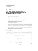
Figure 2.1
Simplified schematic diagram of GaN growth process
Figure 2.1 shows the simplified schematic diagram of the GaN growth
40
Chapter 2
Growth and Characterizations
process. Although the actual growth process of GaN is complicated, it basically
consists of the following four steps: 1) Ga(CH3)3 diffusion through the boundary layer
to the substrate, 2) surface reactions, 3) formation of GaN, and 4) removal of the
reaction products.
All the GaN-based samples discussed in this thesis were grown with an
EMCORE D125 vertical-geometry rotating-disk reactor (RDR) MOCVD system.
The schematic diagram of this system is shown in Fig. 2.2. This system can be
grouped into four major parts, i.e., (1) the gas handling system consisting of alkyl and
hydride sources, necessary gases and all instruments used to control the gas flows and
mixtures; (2) the reaction chamber, where the pyrolysis reaction and deposition occur,
and the loadlock; (3) the heating and temperature controlling system; and (4) the
exhaust, pumping and pressure controlling system. [Ludowise1985]
bubblers
Figure 2.2 Schematic diagram of an EMCORE D125 RDR MOCVD system
(Courtesy of EMCORE corporation)
For the gas handling system, it mainly comprises the sources (precursors and
41
Chapter 2
Growth and Characterizations
other necessary gases), and the gas mixing system (or manifold). The purpose of the
gas handling system is to deliver precisely metered amount of uncontaminated
reactants into the growth chamber without the transients due to the changes of
pressure or gas flows. In this work, trimethylgallium (TMGa), trimethylindium (TMIn)
(from Epichem) were used as the group-III precursors of gallium (Ga) and indium (In),
respectively. Highly purified ammonia (NH3) (ammonia blue from Solkatronic) was
used as the group-V precursor of nitrogen (N). Highly purified H2 and highly purified
N2 (from National Oxygen) were used as the carrier gases. Extra purifiers are also
used for further reduction of oxygen and other contaminants in the highly purified
gases of NH3, N2 and H2 to the order of ppb (parts per billion). They are Matheson
Nanochem NH3 purifier, Mykrolis Aeronex N2 purifier and Johnson Mathey H2
purifier.
In order to control the reaction precisely, a specially designed mass flow
controllers (MFC) can accurately and reliably measure and control the molar flow
rates of the gases. For gas phase sources such as NH3, H2 and N2, which are stored in
pressurized cylinders, the MFC can be solely used to control the molar mass flow
rates precisely. The maximum flow rates for NH3, H2 and N2 are 20 L, 10 L and 10 L,
respectively. For solid or liquid phase sources such as metalorganic precursors of
TMGa and TMIn, which are stored in the stainless-steel cylinders called bubblers, the
exact amount of sources is also controlled by the MFC, as well as the pressure
controller and the temperature controller (thermal bath). More specifically, the partial
pressure of the source vapor is actually regulated by precisely controlling the
42
Chapter 2
Growth and Characterizations
temperature of the metal organic source bubbler, and the temperature of metalorganic
sources can be regulated by means of precisely controlling the temperature of the
thermal bath where the metalorganic source bubbler is held. In addition, the pressure
of the bubbler is regulated by the pressure controller. Thus, a controlled amount of
metalorganic precursor can be transported by controlling the exact amount of
abducting gas flow through the bubbler using the MFC:
FMO = Fabduct ×
Pvapor
Pbubbler − Pvapor
,
(2.1)
where FMO is the molar flow rate per minute of the metalorganic precursor, Fabduct is
the molar flow rate of abducting gas, Pvapor is the pressure of the source vapor and
Pbubbler is the pressure of the bubbler. In our system, there are two TMGa cylinders
and two TMIn cylinders. With the control by MFC, the maximum flow rates are 50
sccm from the TMGa#1 cylinder, 200 sccm from the TMGa#2 cylinder, 200 sccm
from the TMIn#1 cylinder, and 1000sccm from the TMIn#2 cylinder. It should be
noticed that, at normal operating temperatures, the TMGa is liquid and TMIn is solid,
and the bubbler temperatures for TMGa and TMIn are -10 oC and 30 oC, respectively.
The other important part of the gas handling system is the gas mixing system,
or the manifold. At the manifold, the individual reactants are either combined and
switched to the growth chamber or vented to the exhaust line. The manifold also
keeps the delivery pressures of the growth chamber and exhaust line in balance. This
pressure balance is very important to stabilize the gas flow to obtain the atomically
abrupt interfaces in the multi-layer heterostructures. In our EMCORE D125 MOCVD
system, there are three manifolds, one for the group-V precursor (NH3) and carrier
43
Chapter 2
Growth and Characterizations
gases (H2 or/and N2), the second for the trimethylaluminum (TMAl) precursor, and
the third for the other precursors. The purpose of separating TMAl from other alkyl
precursors is to prevent parasitic reactions of Al because Al is very reactive, and
TMAl is not used in this work. A push line that always injects H2 is also added to each
manifold to achieve the fast delivery of the reactants through the gas tube to the
growth chamber and to minimize the switching time during the growth of an abrupt
interface.
For the reaction chamber, our EMCORE D125 MOCVD system has a
vertical-geometry RDR. It is made of stainless steel and is water-cooled. A loadlock
maintained at high vacuum with a turbo molecular pump is connected to the reaction
chamber and it can transfer wafers in/out of the reaction chamber. In RDR, substrates
sit on a circular horizontal disk, called a wafer carrier. For our system, the wafer
carrier is 5.25-inch in diameter, which allows up to three 2-inch wafers to be grown
simultaneously. Also, the wafer carrier is supported by a spindle which is connected to
a motor. Thus, during the growth, the wafer carrier can rotate at a high speed, i.e.,
1000 revolution per minute (rpm) in our growth cases. This fast rotation rate during
the growth improves the gas flow hydrodynamics over the wafer carrier, leading to
the improvement of the growth rate uniformity across the wafer surface.
In addition, it is noticed that, for the growth of GaN-based quantum wells
and quantum dots, the uniform thickness and composition are essential. In the reaction
chamber of our system, the top flow flange consists of several inlets, through which
the precursors and carrier gases are injected downward. Upon arrival in the growth
44
Chapter 2
Growth and Characterizations
chamber, the separated alkyl and hydride source flows are distributed to different
zones in the top flow flange. The alkyl flow is distributed among the inner and outer
zones, while the hydride and carrier gas flow is distributed among the inner, middle,
and outer zones. The distribution of alkyl flows to each zone is controlled with two
MFCs, while the distribution of hydride and carrier gas flows is adjusted by three
needle valves. Hence, a customized flow distribution can be created and optimized
with setting the MFCs and the individual needle valves. The uniformity of growth rate
and composition can therefore be controlled and optimized by setting the flow
distribution.
Besides the careful control of the growth rate and the composition, accurate
and uniform control of the temperature is also critical. For the growth of quantum
wells, the small oscillation in the temperature may result in the non-uniformity of the
growth rate as well as the composition. The careful temperature control is even more
important for the growth of quantum dots, because the temperature window for the
formation of quantum dots is rather narrow. Hence, in our system, a two-zone
resistive heater system is used, and it consists of an inner heater and an outer heater,
providing uniform temperature across the wafer carrier. [Walker1995] Also, each
heater has its own power supply, proportional-integral-differential (PID) temperature
controller, and a thermocouple. The thermocouples are installed under the heaters,
which measure the corresponding heater temperature. The two heaters, therefore, can
be controlled separately for better growth temperature uniformity [Gurary1994]. In
addition, since the thermocouples do not directly measure the temperature of the
45
Chapter 2
Growth and Characterizations
wafer carrier, two pyrometers are also installed on the top of the reaction chamber to
monitor the temperatures of the inner and outer parts of the wafer carrier separately.
Because the thermocouples only control the heater temperature and the pyrometers
only monitor the temperature of the wafer carrier without the ability to directly
control the heater temperature, a temperature calibration run is usually conducted
before an actual run to ensure the better temperature control during the actual growth.
The temperature calibration run is exactly the same as the actual run except that no
group-III precursors flow into the growth chamber. Thus, with the usage of two-zone
resistive heater system, the growth temperature can be controlled uniformly cross the
wafer carrier up to about 1100oC.
Finally, the pumping and low-pressure control system (or vacuum system) is
an important part for controlling the pressure of the reaction chamber. The vacuum
system basically consists of three parts, i.e., (1) a rotary pump, (2) two stage gas
exhaust particle filters, and (3) a throttle valve. The reaction chamber pressure is
controlled by adjusting the position of the throttle valve flap with a MKS pressure
controller unit. The exhaust gases are pumped out of the reaction chamber by the
pumps. The exhaust particles are trapped by the two-stage particle filters. The toxic
parts in the exhaust gases are then absorbed in the toxic gas absorber unit before the
exhaust gases are released into the environment.
Thus, accurate thickness and composition control in the growth of
GaN-based quantum wells and quantum dots can be effectively achieved through the
careful control of the flow rate, temperature and the pressure in our MOCVD system.
46
Chapter 2
Growth and Characterizations
The uniform growth temperature and pressure during the MOCVD growth will also
help improve the crystal quality of the GaN-based structures.
2.2
Plasma enhanced chemical vapor deposition
(PECVD)
The PECVD technique - i.e., film growth using gas phase precursor
activated in a glow discharge environment - has been widely employed in
semiconductor device fabrication for several decades. It is heavily used for deposition
of nitrides and oxides. The typical diagram of a standard PECVD system is shown in
Fig. 2.3 (a).
Figure 2.3 Diagrams of (a) stand PECVD and (b) PECVD with a plasma box
(Courtesy of Unaxis Semiconductor)
In a PECVD system, the plasma is generated by applying a
radiative-frequency (RF) field to a low-pressure gas. The electrons in the reactor,
which gain sufficient energy from the electric field, collide with gas molecules. Then
47
Chapter 2
Growth and Characterizations
the dissociation and ionization of reactant gases occur, and the energetic species
including ions and radicals are adsorbed on the surface and are able to migrate easily
along the surface. This explains the reason that PECVD can provide good step
coverage. Subsequently, the species adsorbed on the surface are subjected to the
bombardment by charged species such as ions and electrons, rearranged, and reacted
with other adsorbed species. Hence, the thin film is finally grown. [Plummer2000]
Because the RF-induced plasma supplies energy into the reactant gases, the
reactions required for deposition can occur at much lower temperatures. Therefore,
PECVD is a low-temperature (< 400°C) process and the resulting films have one
order of magnitude less stress than those grown by thermal CVD. On the other hand,
the use of plasma in the PECVD growth requires the reliable control of various
plasma parameters such as RF power, pressure, gas flow, as well as the thermal
parameters. The films are usually deposited in the reaction-rate limited regime and the
temperature control is especially important. The advantages of PECVD also include
good adhesion, good step coverage, and compatibility with small-feature sized device
manufacturing.
The PECVD deposition of Si3N4 and SiO2 in this work was performed using
a Nextral (NE) D200 Unaxis system. This system is different from the standard
PECVD system shown in Fig. 2.3 (a). It applies a special reactor design – plasma box
concept – where the plasma is confined in a box made of aluminum, as shown in Fig.
2.3 (b). The plasma box, in which the substrate holder is placed, is located in a
furnace. Because of this design, the accurate control of the substrate temperature is
48
Chapter 2
Growth and Characterizations
allowed as all the surfaces in the plasma box are isothermal and equally exposed to
the plasma. Also, film deposition with excellent uniformities and refractive index can
also be achieved because the plasma discharge is confined in a uniformly heated
reactor. In addition, in this system, the furnace/plasma box assembly is placed in a
vacuum chamber; and a roughing pump is used for the plasma box, while a turbo and
roughing pump system is used for the vacuum chamber. During a process run, the two
separated vacuum systems can produce up to 100 times lower pressure in the vacuum
chamber than in the plasma box. As a result, no contamination can enter the plasma
box during the deposition and the impurities do not contaminate the deposited layers.
Furthermore, because the surfaces in contact with the plasma are smooth and made
exclusively of aluminum, fluorine based plasma can be used to clean the plasma box
after any deposition process, and no manual cleaning procedure is required.
In our NE D200 Unaxis system, an air-cooled solid-state RF generator is
used, which can generate an RF frequency of 13.56 MHz and have the maximum
power of 300W. The system is optimized to rapidly produce a high vacuum
(<3.7×10⁻³ mTorr at 280oC) and high pumping flow rates at working pressures. Also,
the gas box is equipped with six gas lines, including SF6, N2, He, NH3, N2O, and SiH4.
The SF6 gas is used for the plasma cleaning. The He and N2 gases are used for powder
removal and purging after the deposition. The SiH4 and N2O gases are the reaction
sources for SiO2 deposition, while the SiH4 and NH3 gases are for the Si3N4
deposition.
For all the PECVD depositions in this work, the chamber temperature was
49
Chapter 2
Growth and Characterizations
280oC because this temperature is optimized for this system to rapidly produce a high
vacuum as mentioned above. For the Si3N4 deposition, the flow rates for SiH4 and
NH3 were 28 sccm and 54 sccm, respectively. The chamber pressure was 500 mTorr
during the deposition and the RF power was 200 W. The reaction can be expressed as:
3SiH4 + 4NH3 → Si3N4 + 12H2
(2.2)
For the SiO2 deposition, the flow rates of SiH4 and O2 were 30 sccm and 400
sccm, respectively. The chamber pressure was 730 mTorr during the depositon and
the RF power was 100 W. The reaction can be expressed as:
SiH4 + O2 → SiO2 + 2H2
(2.3)
To obtain the growth rates and the refractive indices of the SiO2 and Si3N4
films grown by this system, a calibration was conducted. SiO2 and Si3N4 films with
different thicknesses were grown. The thicknesses of these films were measured by
the step-profiler, and the growth rates were therefore obtained. With the thicknesses
known, the refractive indices of the two materials grown by PECVD can then be
measured using an ellipsometer. The calibrated refractive index for the Si3N4 grown in
the above conditions is about 1.97 at the blue wavelength region with a growth rate of
~ 1 nm/s. The calibrated refractive index for the SiO2 grown in the above conditions is
about 1.45 at the blue wavelength region with a growth rate of ~ 3.3 nm/s. If
compared to the theoretical refractive index values (~ 2.00 for Si3N4 and ~ 1.46 for
SiO2 in the blue wavelength region), the refractive indices of the Si3N4 and SiO2
materials grown by our PECVD system are slightly smaller. This is mainly due to the
deviation of the actual stoicheometry. The silicon nitride and silicon oxide films are
50
Chapter 2
Growth and Characterizations
usually denser and with higher refractive indices in the silicon-rich case. [Martin1991;
Modreanu1998] In our PECVD deposition, the smaller refractive indices, and
therefore the lower density of the silicon oxide and silicon nitride films, could be
attributed to the deposited nitrogen-rich silicon nitride and oxygen-rich silicon oxide.
Nevertheless, we will still refer to the silicon nitride and silicon oxide materials
deposited by our PECVD system as Si3N4 and SiO2 in this thesis.
In this work, the AR and DBR coatings in the GaN-based SESAM structure
were fabricated with SiO2 and/or Si3N4 films grown by this PECVD system, which
will be discussed in detail in Section 5.1. In fact, the exact values of refractive index
(n) and physical thickness (d) of these films are not important; but their product (n×d),
which is called optical thickness of a film, directly determines the center wavelength
of a certain film. Hence, in the calibrations for the AR and DBR coatings, firstly,
according to the above calibrated growth rates and refractive index values, single
layer of SiO2 or Si3N4 with a nominal quarter-wavelength optical thickness was
deposited on a random flat substrate. (Here the quarter-wavelength means a quarter of
the required center wavelength.) For example, for a center wavelength of 425 nm, the
nominal thickness for a quarter-wavelength SiO2 layer is 73 nm. With the calibrated
growth rate of 3.3 nm/s for SiO2, the deposition time is set at 22 s. Assuming that the
substrate is sapphire, the reflectance spectrum of this single-layer SiO2 film on the
sapphire substrate is then measured by a spectrophotometer, which operation principle
will be described in Section 2.3.2. Because sapphire (n=1.67) has a higher refractive
index than SiO2 (n=1.45), the obtained spectrum would show a minimum reflectance
51
Chapter 2
Growth and Characterizations
near 425 nm, whereas if the substrate is made of material with lower refractive index
than the single-layer film material, a maximum reflectance would be observed near
425 nm. The actual wavelength at the minimum reflectance for the single-layer SiO2
film is therefore obtained, which could be deviated from 425 nm. Subsequently, the
PECVD deposition time was adjusted according to the amount of wavelength
deviation from 425 nm, and the above steps are repeated until the wavelength at the
minimum reflectance arrives at the 425 nm. Same procedures can also be conducted
for calibrating a single quarter-layer Si3N4 centered at 425 nm. With the calibrated
growth rate of 1 nm/s for Si3N4, the initial deposition time can be set at 54 nm for a
nominal quarter-wavelength thickness of 54 nm. Finally, with the calibrated
deposition times for quarter-wavelength Si3N4 and SiO2 layers centered at 425 nm,
alternative layers of SiO2 and Si3N4 can be deposited to fabricate a DBR coating
centered at 425 nm. Single quarter-layer AR coatings, or two-layer quarter/quarter AR
coatings can also be fabricated with SiO2 or/and Si3N4. In addition, DBR and AR
coatings centered at other wavelengths can also be calibrated and fabricated using the
similar procedures.
2.3
Characterization techniques
2.3.1 Photoluminescence (PL)
PL spectroscopy is an important non-destructive technique to evaluate the
optical properties of semiconductor materials, especially those direct-bandgap
materials such as III-nitrides. [Perkowitz1993]
52
Chapter 2
Growth and Characterizations
Photoluminescence is a photon emission process resulting from optical
excitation. When a semiconductor is optically excited by photons with energy higher
than the bandgap energy ( h v > E g ) , the electrons can be excited from the valence
band of the semiconductor into its conduction band, and the non-equilibrium electrons
and holes are generated. Then the non-equilibrium electrons and holes, and other
quasi-particles will ultimately recombine through various transitions, which can be
radiative (emission of photons) or non-radiative (emission of phonons). The PL
spectroscope techniques measure and analyze the energy distribution of the emitted
photons from a semiconductor after optical excitation.
There are several radiative recombination mechanisms, including (i)
band-to-band transition, (ii) free electron to acceptor transition, (iii) free hole to donor
transition, and (iv) donor-acceptor pair transition, as indicated in Fig. 2.4.
Figure 2.4 Different radiative recombination mechanisms, (i) band-to-band
transition, (ii) free electron to acceptor transition, (iii) free hole to donor transition,
and (iv) donor-acceptor pair transition. ED is the donor binding energy and EA is the
acceptor binding energy.
53
Chapter 2
Growth and Characterizations
The most common radiative transition in semiconductors is the band-to-band
transition, which occurs between the states in the conduction and valence bands, with
the energy difference known as the bandgap. When working with a new compound
semiconductor, bandgap determination by analyzing the PL spectrum can be
particularly useful. If the shape of the band-to-band PL spectrum from a
direct-bandgap semiconductor is calculated, it is found that the PL spectral shape is
given by
I PL (hω) ∝ (hω − E g )1/ 2 exp[−hω / k BT]
for hω > E g ,
(2.4)
where hω is the emitted photon energy, Eg is the bandgap and kB is the Boltzmann
constant. According to the calculation from Eqn 2.4, the typical shape of a
band-to-band PL spectrum is shown by the dotted curve in Fig. 2.5, while the solid
curve in Fig. 2.5 shows the band-to-band PL spectrum measured from an actual
sample. As can be observed, the experimental curve shows deviation from the
calculated curve especially on the lower photon energy side of the spectrum. This is
because an actual sample does not have perfect crystal quality. The existence of a few
defects will result in the emissions at lower photon energies than the bandgap energy,
and therefore broaden the PL spectrum on the lower photon energy side.
54
Chapter 2
Growth and Characterizations
Figure 2.5 Calculated (dotted curve) and experimental (solid curve) band-to-band
PL spectra for an n-type InSb sample. [Teo2004]
Radiative transitions in semiconductors also involve the free-to-bound
transitions, including the free electron to acceptor transition and the free hole to donor
transition, which are related with the defect levels. The photoluminescence energy
associated with these defect levels can be used to identify specific defects and their
binding energy, and the amount of photoluminescence can be used to determine the
concentration of certain defects. For some semiconductors, they may even contain
both donors and acceptors. Under the equilibrium, some of the electrons from the
donors will be captured by the acceptors. As a result, the sample would contain both
ionized donors and acceptors. The energy of the photon emitted from the
donor-acceptor pair transition will be related with the bandgap of the semiconductor,
the respective binding energies of donor and acceptor levels, as well as the coulomb
interaction energy determined by the distance between the ionized donor and
acceptor.
55
Chapter 2
Growth and Characterizations
Besides the radiative transitions mentioned above, there are also radiative
transitions related with excitons, including free exciton recombination and bound
exciton recombination. For the free exciton recombination, its binding energy can be
obtained according to the hydrogen-atom model, while for the exciton bound to a
certain defect level, the binding energy is determined by the bandgap, free exciton
binding energy, and the bound exciton binding energy, as illustrated in Fig. 2.6.
Figure 2.6 Illustration for free excition transition and bound exciton transition. Eb is
the free exciton binding energy and Ebx is the bound exciton binding energy.
In addition to the radiative transitions, there are also non-radiative transitions
associated with deep defect levels, which presence is normally detrimental to the
material quality and the device performance. Thus, material quality can be measured
by analyzing the amount of radiative recombination. In addition, because the
existence of shallow defects can cause the broadening of the band-to-band PL peak or
even result in the multiple peaks, the crystal quality of the certain material can then be
56
Chapter 2
Growth and Characterizations
estimated by the FWHM of the PL spectrum. The origin of the additional PL peaks
can also be analyzed according to their emission energies and FWHM values. These
techniques were used in this work to study the morphology related optical properties
of InGaN/GaN quantum wells.
The PL measurements in this work were performed using three different
setups. For the room-temperature PL measurements, a Renishaw 2000 micro-PL setup
or an Accent Rapid Photoluminescence Mapping System (RPM 2045) was used, with
the 325-nm He-Cd laser for excitation. The analysis can be done at various excitation
power densities for both systems, and the spatial resolution of the micro-PL setup is 4
μm. In material study, because some defects and structural irregularities manifest
themselves only at low temperature, PL spectra obtained at low temperature are also
important. The above micro-PL system can perform the low-temperature PL
measurements at temperatures down to 77 K, using the liquid nitrogen for cooling. To
achieve lower temperatures, another low-temperature PL system was used. The
schematic setup of the low-temperature PL system is shown in Fig. 2.7. The sample is
located in a cryostat connected to a compressor, and the measuring temperature can be
adjusted from about 4 K to the room temperature. A 325-nm He-Cd laser is used as
the exciting source. The beam is modulated by a chopper at a low frequency (280 Hz),
and is focused to a small spot (0.001 cm2) on the sample surface. This set-up is in a
back-scattering geometry, i.e., the resulting PL is collected from the same surface as
the surface excited by the incident laser. This arrangement allows for separate
focusing of the laser beam and the imaging of PL. The resulting luminescence is then
57
Chapter 2
Growth and Characterizations
collected with two lenses and is coupled into a SPEX 750M monochrometer by which
the luminescence is spectrally dispersed. Subsequently, the dispersed luminescence is
detected by a photomultiplier tube (PMT) with an S-1 type photocathode that is
suitable for detecting light from near-UV to 1200 nm. The DC signals (dispersed
luminescence photon intensities) produced by the PMT are measured using a
STANFORD RESEARCH SYSTEMS SR830 lock-in amplifier. A computer is used
to control the whole system, and to record and process the resulting data.
Figure 2.7
Schematic setup of the low-temperature photoluminescence system
2.3.2 Spectrophotometry
Spectrophotometry is a quantitative study of the electromagnetic spectra. It
involves the use of a spectrophotometer, which can measure the light intensity as a
function of the color, or more specifically, the wavelength of the light. There are many
kinds of spectrophotometers, which are classified according to their operation
58
Chapter 2
Growth and Characterizations
wavelength range, measurement technique, and the spectrum acquisition method. The
important features of spectrophotometers also include their spectral bandwidth and the
linear range.
Spectrophotometers are widely used to study the light absorption,
reflectance and transmittance. They measure quantitatively the fraction of light
passing through a given sample. In a near-IR/VIS/UV spectrophotometer, a light from
a lamp (typically a deuterium gas discharge lamp) is guided through a monochromator,
which picks light of a particular wavelength or certain wavelengths out of the
continuous spectrum. This light passes through the sample which is being measured.
After the sample, the intensity of the remaining light is measured with a photodiode or
other light sensors, and the transmittance at a certain wavelength or wavelength range
is then obtained.
The most common spectrophotometers are operating in the UV and visible
regions of the spectrum; and some of these instruments can even operate into the
near-infrared region. For infrared measurement, it is especially challenging because
virtually everything emits infrared light as thermal radiation, especially at the
wavelengths beyond 5 μm.
In this work, the linear reflectance and transmission spectra of the
InGaN/GaN quantum wells and the SESAM structures were obtained at room
temperature using a Shimadzu UV-1700 UV-Visible Spectrophotometer. This
spectrophotometer covers the wavelength range of 190 – 1100 nm, with the
wavelength accuracy of ± 0.5 nm and the photometric accuracy of ± 0.002. The
59
Chapter 2
Growth and Characterizations
wavelength scanning rates can be adjusted to be approximately 10 – 3000 nm/min.
During the measurements, the directly obtained reflectivity or transmittance values
were not taken as the actual values. A good-quality aluminum film is usually required
for calibration and assumed to have a reflectivity of 100 %.
2.3.3 Atomic force microscopy (AFM)
The AFM operates by measuring the forces between the probe and the
sample, and it is suitable for both conducting and insulating samples. [Sarid1991] The
forces depend on the nature of the sample, the distance between the probe and the
sample, the probe geometry, and sample surface contamination.
Figure 2.8 Schematic drawing of the general components of an AFM system
[Courtesy of Massachusetts Institute of Technology (MIT) AFM homepage]
The general components of an AFM system are illustrated in Fig. 2.8. The
instrument consists of a cantilever with a sharp tip mounted on its end. The cantilever
is typically formed from Si or silicon nitride. The vertical sensitivity depends on the
cantilever length. For topographic imaging, the tip is brought into continuous contact
60
Chapter 2
Growth and Characterizations
with the sample and scanned across the sample surface. Piezoelectric scanners can
translate either the sample under the cantilever or the cantilever over the sample, and
the motion is sensed by a segmented, and position sensitive photodetector. For
example, by using a four quadrant detector, the relative amount of laser light hitting
each quadrant can be used to determine how the tip is deflected as it moves over the
sample surface.
In this work, a Digital Nanoscope III AFM with tapping mode was used to
characterize the morphology of the samples. It can scan the surface area up to 120 μm
× 120 μm (square) and allows the peak-to-valley height value up to 7 μm. The tapping
mode AFM is a development of the contact mode AFM. In tapping mode AFM, the
cantilever on which the tip is mounted oscillates at a frequency near its resonance
(200-400 kHz). The oscillation is driven by a constant driving force and the amplitude
of its oscillation is monitored. If the tip touches the surface at the bottom of each
oscillation, the oscillation amplitude of the cantilever will then be reduced. If the tip
does not touch the surface during an oscillation, the amplitude will be increased. The
feedback control loop of the system then maintains this new amplitude constant as the
oscillating tip scans the surface. The above operation is achieved by the Z component
of the scanner, and the amplitude is adjusted according to the surface topographic
variations during the surface scanning. The most important advantage of tapping
mode AFM over the contact mode AFM is the elimination of the lateral shear forces,
which are often responsible for the sample damage in soft or sticky samples.
[Zhong1993]
61
Chapter 2
Growth and Characterizations
With the AFM scanning, a high-resolution 3-dimensional image of the
sample can be obtained (Fig. 2.9 (a)). Different analysis can then be conducted
according to this 3-dimensional image data. For example, the 2-dimensional surface
profile (or planar image) of the sample can be created using the “flatten” analysis.
(Fig. 2.9 (b)) Different colors in such an image indicate different heights of the
features. The surface roughness root-mean-square (rms) value for the scanned surface
or part of the scanned surface can also be obtained using the “roughness” analysis.
(Fig. 2.9 (c)) The “section” analysis quantifies the departure from the planarity by
measuring small height variations along any direction, on any segment of the image,
as indicated by the cross-sectional lines and measurement cursors in the image. (Fig.
2.9 (d))
Figure 2.9 (a)
62