Design of hybrid marine control systems for dynamic positioning
Bạn đang xem bản rút gọn của tài liệu. Xem và tải ngay bản đầy đủ của tài liệu tại đây (11.38 MB, 207 trang )
DESIGN OF HYBRID MARINE CONTROL SYSTEMS
FOR DYNAMIC POSITIONING
NGUYEN TRONG DONG
NATIONAL UNIVERSITY OF SINGAPORE
2006
DESIGN OF HYBRID MARINE CONTROL SYSTEMS
FOR DYNAMIC POSITIONING
NGUYEN TRONG DONG
(B.Eng. (Hons.), HCMUT)
A THESIS SUBMITTED
FOR THE DEGREE OF DOCTOR OF PHILOSOPHY
DEPARTMENT OF CIVIL ENGINEERING
NATIONAL UNIVERSITY OF SINGAPORE
2006
i
ACKNOWLEDGEMENTS
First of all, I would like to thank my supervisor, Professor Quek Ser Tong, at the
Department of Civil Engineering, NUS, for his encouraging and introducing me this
wonderful research. His trust and scientific excitement inpired me through my research
and I am so lucky to work with him.
I am grateful to my co-supervisor, Professor Asgeir J. Sørensen at the Marine
Technology Department, Norwegian University of Science and Technology (NTNU),
for inviting me to research stay at NTNU. He always shares his knowledge regarding
the marine control systems and this helps me a lot in my research.
I would like to thank my colleagues at NUS and NTNU for their invaluable helps
and supporting me in my research work. I would like to say that it was a pleasure to
work with Øyvind and especially Torgeir Wahl who valuably helped me to conduct
experiments with Cybership III at the Marine Cybernetics Laboratory, NTNU. I want
to thank you all for all your kindly help, support, interest and valuable hints.
I also want to thank my parents and brother, who taught me the value of hard
working by their own examples. They are always my strong support during the whole
difficult time of my research. The acknowledgement would not be complete without
the mention of my girlfriend who is always with me whenever I fell lonely far from
home.
The work has been carried out and supported by the National University of
Singapore Research Scholarship. In addition, Keppel Corporation is great is greatly
acknowledged for sponsoring me the Keppel Professorship Fund for my research stay
at NTNU. Finally, the presentations of three conference papers in the Sixteenth,
Seventeenth and Eighteenth KKCNN Symposiums on Civil Engineering were made
possible with financial support from Lee Foundation.
ii
TABLE OF CONTENTS
ACKNOWLEDGEMENTS I
TABLE OF CONTENTS II
SUMMARY VIII
LIST OF TABLES X
LIST OF FIGURES XII
LIST OF ABBREVIATIONS XVIII
CHAPTER 1 INTRODUCTION 1
1.1 Background 1
1.2 Literature Review 2
1.2.1 Hybrid Control and Supervisory Control 2
1.2.2 Station Keeping of Marine Vessels 4
1.2.3 Low Speed Maneuvering and Transit 11
1.3 Objectives and Scopes 12
1.4 Organization of Thesis 15
CHAPTER 2 MODELLING OF MARINE VESSELS 18
2.1 Introduction 18
2.2 Notation and Kinematics 19
2.2.1 Reference Frames and Notations 19
2.2.2 Kinematics 20
iii
2.3 Floater Dynamics 21
2.3.1 Low Frequency Model 22
2.3.2 Environmental Loads 26
2.3.3 Mooring Loads 28
2.3.4 Wave Frequency Model 32
CHAPTER 3 CONCEPT OF HYBRID MARINE CONTROL SYSTEMS
(HYMARCS) 35
3.1 Introduction 35
3.2 Multi Operational Regime Controller Objectives 36
3.2.1 Changes in Operation Mode 36
3.2.2 Changes in Speed 37
3.2.3 Changes in Environment 37
3.2.4 Fault-Tolerant Control 39
3.3 Control Structure 39
3.3.1 Actuator Controller (Low Level) 39
3.3.2 Plant Controller (High Level) 40
3.3.3 Local Optimization 40
3.4 Concept of Hybrid Controller 41
3.4.1 Concept of Supervisory Control 41
3.4.2 Properties of Supervisory Control 43
3.4.3 Scale-Independent Hysteresis Switching Logic 45
3.5 Conclusions 47
CHAPTER 4 MULTI-OPERATIONAL HYBRID CONTROLLER
STRUCTURE FOR STATION KEEPING AND TRANSIT
OPERATIONS OF MARINE VESSELS 51
iv
4.1 Introduction 51
4.2 Autopilot in Transit Regime 52
4.2.1 Observer Design 52
4.2.2 Controller Design 54
4.3 Station Keeping – Dynamic Positioning 54
4.3.1 Observer Design 54
4.3.2 Controller Design 57
4.4 Controller for Transition from Autopilot to DP 57
4.5 Station Keeping – Positioning Mooring System 59
4.5.1 Observer Design 59
4.5.2 Controller Design 60
4.6 Station Keeping – Transition from DP to PM and vice versa 60
4.7 Experimental Results 61
4.7.1 Switching from DP Mode to SPM Mode 61
4.7.2 Switching from STL Mode to DP Mode 62
4.7.3 Discussions 63
4.8 Conclusions 64
CHAPTER 5 DESIGN OF OBSERVER AND CONTROLLER FOR
DYNAMIC POSITIONING IN MODERATE AND EXTREME
SEAS 81
5.1 Introduction 81
5.2 Observer with Parametrically Adaptive WF Filtering 83
5.2.1 Formulation 84
5.2.2 Simulation and Experimental Results 86
5.3 Observer without WF Filtering 87
v
5.3.1 Formulation 87
5.3.2 Simulation Results 88
5.3.3 Experimental Results 88
5.4 Experiments with AFB in different sea states 89
5.4.1 Overview of Experiments 89
5.4.2 Results and Discussions 90
5.5 Conclusions 92
CHAPTER 6 DESIGN OF HYBRID CONTROLLER FOR DYNAMIC
POSITIONING FROM CALM TO EXTREME SEAS 101
6.1 Introduction 101
6.2 Hybrid Controller DP System Using Multi-output PID Controllers with
Position Measurement 102
6.2.1 Output PID Controller for Calm and Moderate Seas (Models 1 and 2)103
6.2.2 Output PID Controller for Extreme Seas (Model 4) 106
6.2.3 Output PID for Transition Regime between Moderate and Extreme
Seas (Model 3) 108
6.3 Hybrid Controller DP System Using Multi-output PID and AFB Controllers
with Position and Acceleration Measurements 108
6.3.1 Output AFB Controller for Extreme Seas (Model 4) 109
6.3.2 Output PID and AFB for Transition Regime between Moderate and
Extreme Seas (Model 3) 111
6.4 Hybrid Controller DP System Using Multi-output PID and AFB Controllers
with Position, Velocity and Acceleration Measurements 111
6.4.1 Output PID Controller for Calm and Moderate Seas (Model 1 and 2)112
6.4.2 Output AFB Controller for Extreme Seas (Model 4) 114
vi
6.4.3 Output PID and AFB for Transition Regime between Moderate and
Extreme Seas (Model 3) 116
6.5 Stability Analysis 116
6.5.1 Multi-output PID and AFB Controllers, with Position and
Acceleration Measurements 116
6.5.2 Tuning for Supervisory Control 118
6.5.3 Design of the multi-PID controllers 119
6.6 Numerical Simulation Results 120
6.6.1 Overview of Simulation 120
6.6.2 Results 120
6.6.3 Discussions 121
6.7 Experimental Results 122
6.7.1 Overview of Experiments 122
6.7.2 Results and Discussions 123
6.8 Conclusions 126
CHAPTER 7 CONCLUSIONS AND RECOMMENDATIONS FOR
FURTHER WORK 142
7.1 Conclusions 142
7.2 Recommendations for Further Work 145
REFERENCES 147
APPENDIX A STABILITY ANALYSIS OF HYBRID CONTROL FOR DP
SYSTEM 158
A.1 Fundamental Stability Analysis 158
vii
A.2 Stability Analysis of Controller in Transition Regime between Autopilot and
Dynamic Positioning 159
A.3 Stability Analysis of Observer without WF Filtering for Output PID 162
A.4 Stability Analysis of Observer without WF Filtering for Output AFB 164
A.5 Proof of Proposition 1 165
A.1.1 Part 1 166
A.1.2 Part 2 167
A.1.3 Part 3 168
APPENDIX B MARINE CYBERNETICS LABORATORY 172
APPENDIX C CYBERSHIP III 174
C.1 General Configurations of Cybership III 174
C.2 Bollard Pull Tests of Cybership III 176
C.2.1 Cybership III Thruster Configuration 176
C.2.2 Experimental Setup 177
C.2.3 Thruster Characteristics 178
APPENDIX D MARINE SYSTEMS SIMULATOR 180
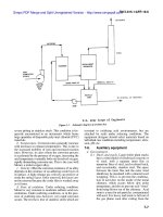
D.1 Introduction 180
D.2 Simulation of Second-Order Wave Load for DP Vessel 180
D.2.1 Formulation 181
D.2.2 Simulation results 182
APPENDIX E PUBLICATIONS AND SUBMITTED PAPERS DURING THIS
PERIOD 186
E.1 Journal papers 186
E.2 Conference papers 186
viii
SUMMARY
Dynamic positioning is critical in floating structures in order to keep them
operational especially for offshore exploration. Marine vessels should optimally be
able to operate in different environmental conditions and different speed regimes but it
is not efficient to have a wide operational window using a single control system.
Hence, the objectives of this thesis are to present the concept of an integrated hybrid
control dynamic positioning system (or so-called “super system”) for marine control,
integrating DP, maneuvering and transit operations under calm, moderate, rough and
extreme environmental conditions. The choice of controller is influenced by three
main parameters, namely function, environment and speed regime. Changes in these
parameters will result in changes in control objectives, constraints, dynamic responses
and disturbance characteristics. Once the choice is decided, switching can be
performed manually or automatically.
Manually switched hybrid marine control system integrating functions for DP,
low speed maneuvering and transit operations was developed. For smooth
performance during switching, weighting functions for the controllers were used.
Guidance and navigation are necessary to smoothly change the desired speed or set-
point. The smooth transformation was verified experimentally using the model ship,
Cybership III, for operating from DP to PM and vice versa.
Automatic switch hybrid control was performed via a switching logic adopting
the concept of supervisory switching, and was developed herein for DP system under
calm to extreme seas. Although station keeping of floating structures under moderate
sea conditions has been well researched, the solutions are not adequate for extreme sea
conditions. Nonlinear passive observer without wave frequency (WF) filtering was
ix
studied by stability analysis, numerical simulations and experiments with the model
ship, Cybership III, to validate this observer proposed by Sørensen et al. (2002) for
extreme seas. The study showed that in extreme seas nonlinear passive observer
without WF filtering stabilized the DP vessel and performed better than nonlinear
passive observer with WF filtering. In addition, the acceleration feedback with PID, in
short AFB controller, was studied for its effectiveness in extreme seas. The
experiments with the Cybership III under three sea states, i.e. moderate, moderately
rough and rough seas, showed that AFB controller improved the performance of DP
vessel compared with that using PID controller only and the level of improvement
seems to increase with increasing sea states. The observer without WF filtering and
AFB controller were recommended for the DP system in extreme seas.
The hybrid control for DP system handling changes of environmental conditions
from calm to extreme sea integrates the conventional controllers for normal seas and
output AFB or output PID without WF filtering from the observer. The hybrid control
DP system adopting the concept of supervisory switching has the ability to
automatically switch among a set of controllers. Stability analysis, numerical
simulations and experiments for the proposed hybrid control using supervisory control
were provided. The performances of the hybrid control DP vessel in simulations and
experiments in varying environmental conditions did not show instability when
switching and it performed better than the single controller DP vessel. Those suggest
that the switching may not have a negative effect on the stability of the whole system
and can be expand the weather window for DP system to extreme conditions by
implementing hybrid control concept.
x
LIST OF TABLES
Table 2.1. Notation for position and velocity (after SNAME, 1950). 33
Table 3.1. Typical Operational Profiles of a PSV, a Shuttle Tanker, an FPSO, and
Drilling & well-intervention vessel 48
Table 3.2. Sub-Functions for Marine Operational Objectives 48
Table 4.1. Summary of experiments: switching from DP to SPM mode. 65
Table 4.2. Environmental conditions. 65
Table 4.3. Summary of operation modes from SPM to DP 65
Table 4.4. Summary of experiments: switching from STL to DP. 65
Table 4.5. Summary of operation modes from STL to DP 65
Table 5.1. Performance and consumed energy indicators (standard deviation values)
normalized with respect to value obtained by single output PID control. 93
Table 5.2. Experiments to investigate effects of AFB. 93
Table 5.3. Empirical performance indicators (standard deviation and RMS values)
normalized with respect to values obtained by conventional PID-control.93
Table 6.1. Definition of Sea State codes (Price and Bishop, 1974) 127
Table 6.2. Sea state definition based on PFW. 127
Table 6.3. Observers and controllers for proposed hybrid DP system using multi-PID
and multi-PID + AFB 127
Table 6.4. Environmental conditions 127
Table 6.5. Simulation and experimental setup 128
Table 6.6. Performance and consumed energy indicators (standard deviation values)
normalized with respect to value obtained by Case 2. 128
Table 6.7. Experiments with hybrid control for DP vessel under changes of
environmental conditions from short to long waves (constant H
s
). 128
Table 6.8. Experiments with hybrid control for DP vessel under changes of
environmental conditions from calm to rough seas (varying H
s
) 128
Table 6.9. Performance and consumed energy indicators (standard deviation values)
normalized with respect to value obtained by single output PID control
(constant H
s
). Experiments with varying environmental conditions from
short to long waves 129
xi
Table 6.10. Performance and consumed energy indicators (standard deviation values)
normalized with respect to value obtained by single output PID control
(varying H
s
). Experiments with varying environmental conditions from
calm to rough sea. 129
Table C.1. Supply vessel main particulars 175
Table C.2. Thruster specifications 176
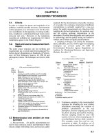
Table C.3. Thrust characteristics 179
Table D.1. Simulation results of Case (a): the fixed vessel 183
Table D.2. Simulation results of Case (b): the DP vessel 183
xii
LIST OF FIGURES
Figure 2.1. Earth-fixed, reference-parallel and body-fixed frame. 34
Figure 2.2. 6-DOF mode of motion. 34
Figure 3.1. Control objectives for different marine operations. 49
Figure 3.2. Control structure (Sørensen, 2005b) 49
Figure 3.3. Switched DP system 49
Figure 3.4. Injected DP system in cascade with process based on Hespanha (2001) 50
Figure 3.5. Scale-independent hysteresis switching logic, Hespanha (2001) 50
Figure 4.1. Various marine operations of a shuttle tanker 66
Figure 4.2. Concept of hybrid controller for marine operations from transit to station
keeping. 66
Figure 4.3. Weighting function
α
1
and
α
2
, with q = 8, p = 2.5, r = 12 67
Figure 4.4. The Cybership III with SPM. 67
Figure 4.5a. Test 1a: performance of switching from DP to SPM mode and vice versa
of the shuttle tanker: measured position and heading (solid) and their LF
estimation (grey). 68
Figure 4.5b. Test 1a: control force and moment: force and moment produced by
thrusters (solid), force and moment produced by the mooring system
(dash) 68
Figure 4.6a. Test 2a: performance of switching from DP to SPM mode and vice versa
of the shuttle tanker: measured position and heading (solid) and their LF
estimation (grey). 69
Figure 4.6b. Test 2a: control force and moment: force and moment produced by
thrusters (solid), force and moment produced by the mooring system
(dash) 69
Figure 4.7a. Test 3a: performance of switching from DP to SPM mode and vice versa
of the shuttle tanker: measured position and heading (solid) and their LF
estimation (grey). 70
Figure 4.7b. Test 3a: control force and moment: force and moment produced by
thrusters (solid), force and moment produced by the mooring system
(dash) 70
xiii
Figure 4.8a. Test 4a: performance of switching from DP to SPM mode and vice versa
of the shuttle tanker: measured position and heading (solid) and their LF
estimation (grey). 71
Figure 4.8b. Test 4a: control force and moment: force and moment produced by
thrusters (solid), force and moment produced by the mooring system
(grey) 71
Figure 4.9a. Test 5a: performance of switching from DP to SPM mode and vice versa
of the shuttle tanker: measured position and heading (solid) and their LF
estimation (grey). 72
Figure 4.9b. Test 5a: control force and moment: force and moment produced by
thrusters (solid), force and moment produced by the mooring system
(dash) 72
Figure 4.10a. Test 6a: performance of switching from DP to SPM mode and vice versa
of the shuttle tanker: measured position and heading (solid) and their LF
estimation (grey). 73
Figure 4.10b. Test 6a: control force and moment: force and moment produced by
thrusters (solid), force and moment produced by the mooring system
(dash) 73
Figure 4.11. STL model: four mooring lines connected to the floating turret which can
be connected and disconnected to the bow of the Cybership III. The turret
can be freely rotated relatively to the mooring system. 74
Figure 4.12. Three mooring system configurations. 74
Figure 4.13a. Test 1b: performance of switching from STL to DP mode of the shuttle
tanker: measured position and heading (solid) and their LF estimation
(grey) 75
Figure 4.13b. Test 1b: control force and moment: force and moment produced by
thrusters (solid), force and moment produced by the mooring system
(dash) 75
Figure 4.14a. Test 2b: performance of switching from STL to DP mode of the shuttle
tanker: measured position and heading (solid) and their LF estimation
(grey) 76
Figure 4.14b. Test 2b: control force and moment: force and moment produced by
thrusters (solid), force and moment produced by the mooring system
(dash) 76
Figure 4.15a. Test 3b: performance of switching from STL to DP mode of the shuttle
tanker: measured position and heading (solid) and their LF estimation
(grey) 77
xiv
Figure 4.15b. Test 3b: control force and moment: force and moment produced by
thrusters (solid), force and moment produced by the mooring system
(dash) 77
Figure 4.16a. Test 4b: performance of switching from STL to DP mode of the shuttle
tanker: measured position and heading (solid) and their LF estimation
(grey) 78
Figure 4.16b. Test 4b: control force and moment: force and moment produced by
thrusters (solid), force and moment produced by the mooring system
(dash) 78
Figure 4.17a. Test 5b: performance of switching from STL to DP mode of the shuttle
tanker: measured position and heading (solid) and their LF estimation
(grey) 79
Figure 4.17b. Test 5b: control force and moment: force and moment produced by
thrusters (solid), force and moment produced by the mooring system
(dash) 79
Figure 4.18a. Test 6b: performance of switching from STL to DP mode of the shuttle
tanker: measured position and heading (solid) and their LF estimation
(grey) 80
Figure 4.18b. Test 6b: control force and moment: force and moment produced by
thrusters (solid), force and moment produced by the mooring system
(grey) 80
Figure 5.1. Concept of adaptive observer 94
Figure 5.2. Estimated peak frequency of wave from observer with parametrically
adaptive WF filtering – simulation result 95
Figure 5.3. Measured position and heading (grey) and corresponding LF (black)
estimates from observer with parametrically adaptive WF filtering –
simulation result 95
Figure 5.4. Estimated peak frequency of wave from observer with parametrically
adaptive WF filtering – experimental result 96
Figure 5.5. Measured position and heading (grey) and corresponding LF (black)
estimates from observer with parametrically adaptive WF filtering –
experimental result 96
Figure 5.6. Standard deviation of (a) position; and (b) commanded control force and
moment, in increasing sea states of the DP vessel using observer with WF
filtering 97
Figure 5.7. Performance of DP vessel using observer with WF filtering and output PID
in extreme sea (Test 1a) 97
xv
Figure 5.8. Performance of DP vessel using observer without WF filtering and output
PID in extreme sea (Test 1b) 97
Figure 5.9. Performance of DP vessel using observer without WF filtering and output
AFB in extreme sea (Test 1c) 97
Figure 5.10. Performance of PID in moderate sea, Test 2a. 98
Figure 5.11. Performance of AFB in moderate sea, Test 2a 98
Figure 5.12. Performance of PID in moderately rough sea, Test 2b. 99
Figure 5.13. Performance of AFB in moderately rough sea, Test 2b. 99
Figure 5.14. Performance of PID in rough sea, Test 2c 100
Figure 5.15. Performance of AFB in rough sea, Test 2c. 100
Figure 6.1. Concept of hybrid controller DP system using discrete switching signal.130
Figure 6.2. Weighting function in (a) test 1b and 1c, (b) test 2b and 2c. 130
Figure 6.3. Position and heading of DP vessel in Case 1 using single output PID 131
Figure 6.4. Estimated PFW in Case 1 131
Figure 6.5. Position and heading of DP vessel in Case 2 with hybrid controller using
multi-output PID. 132
Figure 6.6. Estimated PFW and switching signal,
σ
, in Case 2 132
Figure 6.7. Performance of DP vessel in Case 3 with hybrid controller using multi-
output PID and AFB 133
Figure 6.8. Estimated PFW and switching signal,
σ
, in Case 3 133
Figure 6.9. Performance of DP vessel in Test 1a using single output PID controller
from short to long waves 134
Figure 6.10. Estimated PFW in Test 1a 134
Figure 6.11. Performance of DP vessel in Test 1b using hybrid controller using multi-
PID controller 135
Figure 6.12. Estimated PFW and switching signal,
σ
, in Test 1b 135
Figure 6.13. Performance of DP vessel in Test 1c using hybrid controller using multi
output PID and AFB 136
Figure 6.14. Estimated PFW and switching signal,
σ
, in Test 1c 136
Figure 6.15. Performance of DP vessel in Test 2a using single output PID controller
from calm to rough sea 137
xvi
Figure 6.16. Estimated PFW in Test 2a. 137
Figure 6.17. Estimated WF motion in 7 sea states (Test 2a) 138
Figure 6.18. Performance of DP vessel in Test 2b using hybrid controller using multi-
PID controller 138
Figure 6.19
.
Estimated PFW and switching signal,
σ
, in Test 2b 139
Figure 6.20. Estimated WF motion in 7 sea states (Test 2b) 139
Figure 6.21. Performance of DP vessel in Test 2c using hybrid controller using multi
output PID and AFB 140
Figure 6.22. Estimated PFW and switching signal,
σ
, in Test 2c 140
Figure 6.23. Estimated WF motion in 7 sea states (Test 2c) 141
Figure B.1. The basin of the MCLab 173
Figure B.2. The single flap wave generator of the MCLab. 173
Figure B.3. Four cameras mounted on the towing carriage for capturing position of
model vessel 173
Figure C.1. Cybership III 175
Figure C.2. PC in control room 176
Figure C.3. Thruster distance 176
Figure C.4. Experimental setup for test (a) Port Main thruster at 0
o
, (b) Starboard Main
thruster at 0
o
, (c) Port Main thruster at 30
o
, (d) Starboard Main thruster at
30
o
, and (e) Front Azimuth thruster at 0
o
. 177
Figure C.5. Experimental setup for test (f) Front Azimuth thruster at 90
o
, and (g)
Tunnel thruster. 177
Figure C.6. Thrust characteristics for (a) Port Main at thruster 0
o
, (b) Starboard Main
thruster at 0
o
, (c) Port Main thruster at 30
o
, (d) Starboard Main thruster at
30
o
, (e) Front Azimuth thruster at 0
o
, (f) Front Azimuth thruster at 90
o
,
and (g) Tunnel thruster 178
Figure D.1. An example of to simulating DP vessel using MSS 181
Figure D.2. Second-order wave-drift load acting on fixed vessel. 183
Figure D.3. Performance of DP vessel with mean wave-drift load simulation. 184
Figure D.4. Mean wave-drift load acting on the DP vessel. 184
xvii
Figure D.5. Performance of DP vessel with filtered Newman second-order wave-drift
load simulation 185
Figure D.6. Filtered Newman second-order wave-drift load acting on the DP vessel.185
xviii
LIST OF ABBREVIATIONS
AFB Acceleration Feedback + PID
CTOL Conventional Take-Off and Landing
DOF Degree of freedom
DP Dynamic positioning
FFT Fast Fourier transform
FPSO
Floating Production Storage and Off-loading
GNC Guidance and navigation control
HyMarCS Hybrid Marine Control System
IMU Inertial measurement unit
ISS Input-to-state stable
JONSWAP JOint North Sea WAve Project
LF Low frequency
LNC Local network control
LQG Linear Quadratic Gaussian
MCLab Marine Cybernetic Laboratory
MIMO Multi-input multi-output
MCSim Marine Cybernetics Simulator
MSS Marine Systems Simulator
PDE Partial differential equations
PFW Peak frequency of wave
PID Proportional – Integral – Derivative
PM Positioning Mooring
POSMOOR ATA/TA Position Mooring with Automatic Thruster Assistance/Thruster
Assistance
xix
PSV Platform supply vessel
RMS Root mean square
ROV Remotely operated vehicle
SISO Single-input single-output
SNAME Society of Naval Architects & Marine Engineers
SPM Single Point Mooring
STL Submerged Turret Loading
UGES Uniformly globally exponential stability
ULES Uniformly locally exponential stability
VOC Vessel Operational Condition
VSTOL Vertical and/or Short Take-Off and Landing
VTOL Vertical Take-Off and Landing
WF Wave frequency
Chapter 1 Introduction
1
CHAPTER 1
INTRODUCTION
1.1 Background
Marine business covers three main clusters: shipping/transportation, offshore
exploration and exploitation of hydrocarbons, and aquaculture/fisheries. In all three
clusters, marine vessel is one major common element. Nowadays, marine vessels are
required to operate in different environmental conditions and different speed regimes.
Safety and cost effectiveness are primary considerations in such operations. It is
important to increase the operational availability making it possible to conduct all-year
marine operation, such as sub-sea installation and intervention, offloading, diving,
drilling, and laying of pipes in harsh environments. In particular, when conducting
marine operations in deep water, the operations are more time consuming, and hence
more sensitive to changes in sea states. Therefore, marine control systems must be
designed so that vessel can operate in many different operational and environmental
conditions.
This motivates the design of nonlinear control since the dynamics of the process,
the constraints, and the objectives of the controllers change significantly in the
different operational conditions. There are two obvious solutions for this nonlinear
problem: design one unique nonlinear controller or combine different controllers. The
design of a unique nonlinear controller may be complicated or even impossible since
the dynamics of the process changes significantly with various operational regimes. In
addition, it is difficult to satisfy many control objectives using only one controller. It
is therefore not surprising that few industrial applications adopt this control strategy.
Chapter 1 Introduction
2
The combination of many controllers, denoted as hybrid control, on the other
hand, may appear to be a simpler solution. In this control strategy, the dynamics of the
process is simplified in each operational regime. The design of controller
corresponding to a particular operational regime is straightforward since the simplified
dynamics of the process are well-formulated linear/nonlinear systems. With a multi-
operational hybrid controller structure, it is easier to satisfy different control
objectives. Although the drawback could be a bundle of controllers with chattering
problem, this control strategy has been implemented widely in many industrial
applications using ad-hoc solutions.
The state of research in hybrid control to integrate different controllers into a
system will be reviewed in the following section. Conventional hybrid control using
ad-hoc solutions in flight control and control of land-based vehicles will be presented.
The literature review will focus on the theory of supervisory control developed
systematically for hybrid control. Review on the control for station keeping and transit
of the marine vessel in different environmental conditions will also be presented.
Based on these reviews, the feasibilities of adopting hybrid control in marine control
system will be explored.
1.2 Literature Review
1.2.1 Hybrid Control and Supervisory Control
Gain scheduling has been commonly used in the flight control due to its
simplicity (McLean, D., 1990; Wang and Balakrishnan, 2002; and Oosterom and
Babuška, 2005). The nonlinear dynamics of conventional aircraft is linearized for
different operational conditions associated with different speed regimes. A set of linear
controllers are designed corresponding to those linear systems. Although the
controllers may be similar, the controller gains are different. For a vector-thrust
Chapter 1 Introduction
3
Vertical and/or Short Take-Off and Landing (VSTOL) aircraft, the aircraft’s dynamics
is simplified into three modes: Conventional Take-Off and Landing (CTOL), Vertical
Take-Off and Landing (VTOL) and TRANSITION. The simplified state space
equations are nonlinear and non-minimal phase. Stability in the sense of Lyapunov
has been used to prove the stability of this system across switching boundary (Oishi
and Tomlin, 1999 and 2000). There has been an attempt to combine human factors
and other controllers since the pilot can also be considered as a controller (Oishi et al.,
2002).
In land-based vehicle control, the strategy for combination of controllers, known
as local network control (LNC), is similar to gain scheduling presented above. A set of
empirically parametric first-order linear models, valid locally in some operational
regimes, have been used to mathematically model the nonlinear dynamics of the
process (Hunt et al., 1996a). It is noted that these linear models do not necessarily
contain any physical equilibriums. The local controller designs are based upon those
linear models and combined by weighting functions (Hunt et al., 1997). An illustration
of this control strategy is the LNC designed for autonomous vehicle steering (Hunt et
al., 1996b).
In marine control system, Smogeli et al. (2004) proposed the hybrid thruster
controller to combine torque control for low and moderate loading conditions of
thruster, and power control for high loading condition. In low loading, the control
objective is to produce accurate propeller torque. In high loading, the objective is to
avoid unintended oscillations and peaks in power consumption preventing blackout.
By combining these two controllers, the operational regime of a thruster can be
extended to provide safer high loading conditions.
Chapter 1 Introduction
4
The strategies presented above have been developed for specific problems.
Furthermore, those strategies are applicable for a small number of candidate
controllers. In some applications, the switching among the controllers may lead to
instability (Liberzon and Morse, 1999). Therefore, more general approaches need to be
developed to prevent instability and chattering (frequent switch). Extensive work has
focused on systematic approach to combine a set of controllers (Hespanha, 2001;
Hespanha and Morse (2002); Hespanha, et al., 2003; and the references therein). This
control strategy, so-called supervisory control, aims to switch among the linear or
nonlinear controllers according to their operational regimes through a specially
designed discrete logic to guarantee the stability of the whole system. It is therefore a
switched and a hybrid system. Supervisory control is more advantageous than adaptive
control (Åström and Wittenmark, 1995) in terms of rapid adaptation, flexibility and
modularity, and decoupling between supervision and control. One of the applications
of supervisory switching control was illustrated by Böling et al. (2005) on multi-model
PID controller for a nonlinear pH neutralization process.
In the following subsections, an overview of station keeping and transit for
marine control systems will be addressed. In addition, previous studies on station
keeping in moderate and extreme seas will also be presented. These serve as
background for the hybrid marine control systems developed in this thesis.
1.2.2 Station Keeping of Marine Vessels
The floating vessels are kept in position by position mooring without or with
thruster assistance (PM) systems, or exclusively by only thrusters known as dynamic
positioning (DP). The term positioning control is here used to denote either PM or DP
(Sørensen, 2005b).