Performance analysis of space time block coded systems with channel estimation
Bạn đang xem bản rút gọn của tài liệu. Xem và tải ngay bản đầy đủ của tài liệu tại đây (8.83 MB, 166 trang )
Performance Analysis of
Space-Time Block Coded Systems
with Channel Estimation
Shan Cheng
M.Eng, Zhejiang University, P.R. China
A THESIS SUBMITTED
FOR THE DEGREE OF DOCTOR OF PHILOSOPHY
DEPARTMENT OF ELECTRICAL AND COMPUTER ENGINEERING
NATIONAL UNIVERSITY OF SINGAPORE
May 2006
Ackowledgements
I would like to express my profound gratitude to my supervisors: Dr. A. Nal-
lanathan and Prof. P. Y. Kam, for their invaluable guidance and endless patience
throughout the entire duration of my Ph.D course.
I would like to thank my parents and other family members. Their love, patience
and understanding have accompanied me all the way along. Special regards to my
beloved grandfather, who departed us in 2004.
I am also thankful to my labmates and friends, not only for their resourceful dis-
cussion in research, but their friendship that makes my life pleasant and joyful.
Abstract
The capacity of a wireless communication system can be increased considerably by using
multiple transmit and receive antennas. The high-data rate provided by such Multiple-
input-multiple-output (MIMO) communication systems make them promising for next-
generation wireless communication. Among these MIMO techniques, space-time block
coding (STBC) has attracted much research interests. The orthogonal structure of
STBC allows every symbol transmitted to be decoupled at the receiver using only linear
processing. Such a symbol-by-symbol receiver is simple yet efficient in implementation
to achieve the gain provided by both transmit and receive diversities.
To coherently decode the STBC, ideally perfect channel state information (CSI)
would be used at the receiver. As the channel information is not readily available
at the receiver in practice, channel estimates are used to perform coherent detection.
The optimum maximum likelihood detector with imperfect channel estimation is far
more computationally complicated than the optimum symbol-by-symbol detector when
perfect CSI is available. In this dissertation, we propose a symbol-by-symbol channel
estimation receiver for STBC systems, which is sub-optimal but computationally efficient
for implementation and can be applied to many channel models with their corresponding
estimators. In particular, we analyze the bit error probability (BEP) performance of this
receiver when minimum mean-square-error estimates are available.
We first derive the BEP performance of the receiver with maximum ratio combining.
The BEP result is given in an exact closed-form expression, which shows the direct
dependence on the mean square error of the channel estimator and the signal-to-noise
ratio. An upper bound is derived to show the maximum diversity order achievable, which
is determined by the product of the numbers of transmit and receive antennas. We
then extend the work to a system with selection combining schemes, where the receiver
selects the received signal from one or several antennas with best quality according to
the channel estimates. Exact closed-form BEP expressions are derived. The results
show that the selection combining systems achieve the diversity gain provided by the
total number of available receive antennas, but independent of the number of antennas
chosen.
Transmit antenna selection (TAS) is a technique to exploit the transmit diversity
other than space-time coding. We propose a TAS/STBC system based on the channel
estimation receiver structure. Through a feedback link, the receiver informs the trans-
mitter which antennas to be used for STBC transmission. This TAS/STBC system has
a simple yet energy-saving structure, while exhibits the full diversity order provided by
the total number of transmit antennas. An BEP upper bound is obtained in closed-
form for the TAS/STBC systems. Particularly, exact BEP expressions are derived for
TAS/STBC systems with single receive antenna, which is important in down-link com-
munication scenarios.
The designs of orthogonal STBC so far known are limited. Unitary space-time
modulation (USTM) treats the whole transmission block as one constellation, and thus
provides many more possible designs while maintaining the orthogonality of signals.
However, there is no systematic method for optimal USTM constellation design. Thus we
propose a systematic algorithm to search for sub-optimal differential unitary space-time
modulation. The constellations generated by the proposed simple algorithm exhibits
better performance than the well-known cyclic codes.
In summary, in this dissertation, space-time block coded communication systems
with imperfect channel estimation are extensively studied and BEP performances are
obtained in closed-forms. Improved algorithms for constellation search are also proposed
for differential unitary space-time modulation systems.
ii
Contents
Abstract i
Contents iii
List of Figures vii
List of Tables x
List of Abbrevaiations xi
1 Introduction 1
1.1 Introduction to Wireless Communication Systems . . . . . . . . . . . . . 1
1.2 A Literature Review of Space-Time Coding . . . . . . . . . . . . . . . . . 2
1.2.1 Simulcast . . . . . . . . . . . . . . . . . . . . . . . . . . . . . . . 3
1.2.2 BLAST . . . . . . . . . . . . . . . . . . . . . . . . . . . . . . . . 3
1.2.3 Space-Time Trellis Codes . . . . . . . . . . . . . . . . . . . . . . . 4
1.2.4 Space-Time Block Codes . . . . . . . . . . . . . . . . . . . . . . . 5
1.2.5 Unitary Space-Time Modulation . . . . . . . . . . . . . . . . . . . 6
1.2.6 MIMO Applications in 3G Wireless Systems and Beyond . . . . . 7
1.3 Research Objective . . . . . . . . . . . . . . . . . . . . . . . . . . . . . . 8
1.4 Structure of the Dissertation . . . . . . . . . . . . . . . . . . . . . . . . . 9
1.5 Research Contributions . . . . . . . . . . . . . . . . . . . . . . . . . . . . 9
iii
CONTENTS
2 MIMO Communication Systems in Wireless Fading Channels 11
2.1 Capacity of MIMO Systems . . . . . . . . . . . . . . . . . . . . . . . . . 11
2.1.1 MIMO Communication System . . . . . . . . . . . . . . . . . . . 11
2.1.2 Capacity Analysis of MIMO Communication System . . . . . . . 13
2.2 Mobile Radio Channels and MMSE Channel Estimation . . . . . . . . . 17
2.2.1 Rayleigh Fading Channel with Butterworth power spectrum density 18
2.2.2 Kalman Filtering for State-Space Channel Model . . . . . . . . . 23
2.2.3 Rayleigh Fading Channel with Jakes’ PSD . . . . . . . . . . . . . 26
2.2.4 Wiener Filtering for Jakes’ Model . . . . . . . . . . . . . . . . . . 30
2.3 Phase-Shift Keying Modulation . . . . . . . . . . . . . . . . . . . . . . . 31
2.4 Summary . . . . . . . . . . . . . . . . . . . . . . . . . . . . . . . . . . . 32
3 BEP Performance Analysis of Orthogonal Space-Time Block Codes 33
3.1 Introduction . . . . . . . . . . . . . . . . . . . . . . . . . . . . . . . . . . 34
3.2 Receiver Structure for Orthogonal STBC . . . . . . . . . . . . . . . . . 37
3.2.1 Definition of Orthogonal STBC . . . . . . . . . . . . . . . . . . . 37
3.2.2 Transmitter Structure . . . . . . . . . . . . . . . . . . . . . . . . 38
3.2.3 Receiver Structure . . . . . . . . . . . . . . . . . . . . . . . . . . 38
3.2.4 Channel Estimator Structure . . . . . . . . . . . . . . . . . . . . 39
3.2.5 Optimum Receiver Structure . . . . . . . . . . . . . . . . . . . . . 43
3.2.6 A Symbol-by-Symbol Receiver Structure . . . . . . . . . . . . . . 44
3.3 BEP Performance Analysis for OSTBC Systems . . . . . . . . . . . . . . 46
3.4 Numerical Results and Discussion . . . . . . . . . . . . . . . . . . . . . 53
3.5 Summary . . . . . . . . . . . . . . . . . . . . . . . . . . . . . . . . . . . 63
4 STBC Communication System with Receive Antenna Selection 64
4.1 Introduction . . . . . . . . . . . . . . . . . . . . . . . . . . . . . . . . . . 65
4.2 System Model and Receiver Structure . . . . . . . . . . . . . . . . . . . . 66
iv
CONTENTS
4.3 Performance Analysis of STBC with Selection Combining . . . . . . . . . 69
4.3.1 Single selection combining . . . . . . . . . . . . . . . . . . . . . . 72
4.3.2 Generalized Selection Combining . . . . . . . . . . . . . . . . . . 76
4.4 Numerical Results and Discussion . . . . . . . . . . . . . . . . . . . . . . 78
4.4.1 Single Selection Combining . . . . . . . . . . . . . . . . . . . . . . 79
4.4.2 Generalized selection combining . . . . . . . . . . . . . . . . . . . 84
4.5 Summary . . . . . . . . . . . . . . . . . . . . . . . . . . . . . . . . . . . 86
5 STBC Communication System with Transmit Antenna Selection 88
5.1 Introduction . . . . . . . . . . . . . . . . . . . . . . . . . . . . . . . . . . 88
5.2 System Model . . . . . . . . . . . . . . . . . . . . . . . . . . . . . . . . . 89
5.3 Performance Analysis of STBC with TAS . . . . . . . . . . . . . . . . . . 92
5.3.1 An Upper Bound for BEP . . . . . . . . . . . . . . . . . . . . . . 93
5.3.2 Exact BEP Analysis for TAS Systems . . . . . . . . . . . . . . . . 94
5.4 Numerical Results and Discussion . . . . . . . . . . . . . . . . . . . . . 96
5.5 Summary . . . . . . . . . . . . . . . . . . . . . . . . . . . . . . . . . . . 105
6 Constellation Design for Unitary Space-Time Modulation 106
6.1 Unitary Space-Time Modulation . . . . . . . . . . . . . . . . . . . . . . . 106
6.1.1 Constellations that Achieve Capacity . . . . . . . . . . . . . . . . 106
6.1.2 Unitary Space-Time Modulation . . . . . . . . . . . . . . . . . . . 109
6.1.3 Differential Unitary Space-Time Modulation . . . . . . . . . . . . 110
6.1.4 Constellation Design Criteria for DUSTM . . . . . . . . . . . . . 114
6.1.5 A Revisit of Cyclic Designs . . . . . . . . . . . . . . . . . . . . . 118
6.2 Constellation Design for Unitary Space-Time Modulation . . . . . . . . . 119
6.2.1 DUSTM Constellation Designs Based on Rotation Matrices
(Scheme I) . . . . . . . . . . . . . . . . . . . . . . . . . . . . . . . 120
v
CONTENTS
6.2.2 DUSTM Constellation Designs Based on Full-Rotation Matrices
(Scheme II) . . . . . . . . . . . . . . . . . . . . . . . . . . . . . . 125
6.3 Numerical Results and Discussion . . . . . . . . . . . . . . . . . . . . . . 131
6.4 Summary . . . . . . . . . . . . . . . . . . . . . . . . . . . . . . . . . . . 136
7 Conclusions and Proposals for Future Research 137
7.1 Conclusions . . . . . . . . . . . . . . . . . . . . . . . . . . . . . . . . . . 137
7.2 Proposals for Future Research . . . . . . . . . . . . . . . . . . . . . . . . 139
Bibliography 144
List of Publications 153
vi
List of Figures
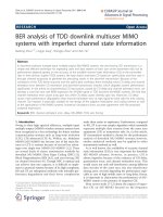
1.1 Delay Diversity and Trellis Space-Time Code . . . . . . . . . . . . . . . . 5
2.1 MIMO System Model . . . . . . . . . . . . . . . . . . . . . . . . . . . . . 12
2.2 Communication channel model . . . . . . . . . . . . . . . . . . . . . . . . 18
2.3 Markov signal model for Kalman filter . . . . . . . . . . . . . . . . . . . 19
2.4 Simulated p.d.f of 1BTW channel model . . . . . . . . . . . . . . . . . . 20
2.5 Simulated correlation functions of 1BTW channel model . . . . . . . . . 21
2.6 Simulated p.d.f of 3BTW channel model . . . . . . . . . . . . . . . . . . 23
2.7 Simulated correlation functions of 3BTW channel model . . . . . . . . . 24
2.8 Kalman Filter Structure . . . . . . . . . . . . . . . . . . . . . . . . . . . 24
2.9 Simulated p.d.f of Jakes’ channel model . . . . . . . . . . . . . . . . . . . 26
2.10 Simulated correlation functions of Jakes’ channel model . . . . . . . . . . 27
2.11 Channel samples of size one thousand for different models . . . . . . . . 29
2.12 Linear Wiener Filter Model . . . . . . . . . . . . . . . . . . . . . . . . . 31
2.13 Constellation maps of PSK signaling . . . . . . . . . . . . . . . . . . . . 32
3.1 Decision feedback channel estimation STBC system . . . . . . . . . . . . 41
3.2 PSAM channel estimation STBC system . . . . . . . . . . . . . . . . . . 41
3.3 PSAM frame structure . . . . . . . . . . . . . . . . . . . . . . . . . . . . 42
3.4 Theoretical BEP performance of Alamouti’s STBC under BTW channel . 54
3.5 Theoretical BEP performance of Alamouti’s STBC under 1BTW channel 55
vii
LIST OF FIGURES
3.6 Theoretical BEP floor under BTW channel . . . . . . . . . . . . . . . . . 56
3.7 Theoretical BEP performance with multiple transmit antennas . . . . . . 58
3.8 Theoretical comparison between full- and half- rate STBC’s . . . . . . . 59
3.9 Theoretical bounds of BEP performance for different STBC’s . . . . . . . 60
3.10 BEP of BPSK with Alamouti’s STBC with one receive antenna . . . . . 61
3.11 BEP performance of 4 × 4 rate-3/4 STBC with 3BTW . . . . . . . . . . 62
3.12 BEP performance of 4 × 4 rate-3/4 STBC with PSAM . . . . . . . . . . 63
4.1 System model of STBC with selection combining . . . . . . . . . . . . . 69
4.2 BEP Performance of 1-Tx system with single selection combining . . . . 79
4.3 Performance comparison between MRC and SSC systems . . . . . . . . . 80
4.4 Performances QPSK and 8PSK modulation with SSC and Alamouti’s STBC 81
4.5 Performance comparison among different STBC’s with SSC . . . . . . . . 82
4.6 Performance comparison of different STBC’s against channel fade rate . . 83
4.7 Performance of GSC with 1-Tx and 4-Rx . . . . . . . . . . . . . . . . . . 84
4.8 Performance of Alamouti’s STBC with dual selection combining . . . . . 85
4.9 Mean output of the estimated SNR with single and dual selection combining 86
5.1 System model of STBC with TAS . . . . . . . . . . . . . . . . . . . . . . 90
5.2 Performance of Alamouti’s STBC with transmit antenna selection . . . . 97
5.3 Performance of the 4 ×4, rate 3/4 STBC with transmit antenna selection 98
5.4 Performance comparison among different STBC’s with M
X
= 4 . . . . . 99
5.5 Performance comparison among different STBC’s with M
X
= 8 . . . . . 100
5.6 Performance comparison between TAS and STBC with M
X
= 2 . . . . . 101
5.7 Theoretical and simulation performances of Alamouti’s STBC with M
X
=
4 . . . . . . . . . . . . . . . . . . . . . . . . . . . . . . . . . . . . . . . . 102
5.8 Performances comparison of TAS and STBC with M
X
= 2 . . . . . . . . 103
5.9 Performances comparison of TAS and STBC with M
X
= 4 . . . . . . . . 104
viii
LIST OF FIGURES
6.1 Diversity product sample ζ
0l
when M
T
= 4, L = 16 . . . . . . . . . . . . 113
6.2 Diversity product function distribution with constellation size L = 16 . . 129
6.3 Demonstration of algorithm complexities . . . . . . . . . . . . . . . . . . 130
6.4 SEP of DUSTM with M
T
= 2 and L = 5, 7, 9 . . . . . . . . . . . . . . . 132
6.5 SEP of DUSTM with M
T
= 2 and L = 8, 16, 32, 64 . . . . . . . . . . . . 132
6.6 SEP of DUSTM with M
T
= 2 under fast fading . . . . . . . . . . . . . . 133
6.7 SEP of DUSTM with M
T
= 4, L = 4, 32, 64 . . . . . . . . . . . . . . . . 133
6.8 SEP of DUSTM with M
T
= 8, L = 8, 32, 64 . . . . . . . . . . . . . . . . 134
6.9 SEP of DUSTM with L = 64 under fast fading . . . . . . . . . . . . . . . 134
7.1 Examples of relay diversity . . . . . . . . . . . . . . . . . . . . . . . . . . 141
7.2 Selection relay diversity . . . . . . . . . . . . . . . . . . . . . . . . . . . 142
ix
List of Tables
3.1 Parameters list for exact BEP evaluation . . . . . . . . . . . . . . . . . . 53
3.2 Parameters list for lower and upper bound of BEP evaluation . . . . . . 53
6.1 Diversity products of different constellation design schemes . . . . . . . . 124
6.2 Comparison of Diversity products of Scheme II against cyclic codes . . . 127
6.3 Diversity product and diversity sum of the proposed constellation . . . . 128
6.4 Run-time comparison of algorithms . . . . . . . . . . . . . . . . . . . . . 130
x
List of Abbreviations
1BTW first-order Butterworth
2G second-generation
3BTW third-order Butterworth
3G third-generation
4G fourth-generation
ADF actual decision feedback
AWGN additive white Gaussian noise
BEP bit error probability
BLAST Bell-lab Layered Architecture of Space-
Time
COD complex orthogonal designs
CSI channel state information
DD differential detection
DF decision-feedback
DSC dual selection combining
DUSTM differential unitary space-time modula-
tion
EGC equal gain combining
EM expectation-maximization
GSC generalized selection combing
i.i.d. independent, identically distributed
IDF ideal decision feedback
KF Kalman filter
MGF moment generating function
MIMO multiple-input-multiple-output
MISO multi-input-single-output
ML maximum-likeliho od
MMSE minimum mean squared error
MRC maximum ratio combining
MSE mean square error
p.d.f. probability density function
PEP pair-wise error probability
PSAM pilot-symbol assisted modulation
PSD power spectrum density
PSK phase-shift keying
r.v. random variable
Rx receive antenna
SBS symbol-by-symbol
SEP symbol error probability
SIMO single-input-multi-output
SNR signal-to-noise ratio
SSC single selection combining
STBC space-time blo ck codes
STTC space-time trellis codes
TAS transmit antenna selection
TCM trellis coded modulation
Tx transmit antenna
USTM unitary space-time modulation
WF Wiener filter
WLAN wireless local-area network
xi
Chapter 1
Introduction
The ability to communicate with people on the move has evolved remarkably ever
since 1897, when Guglielmo Marconi first demonstrated continuous contacts with ships
sailing the English Channel using a radio. More recently, the technical breakthroughs in
digital and radio frequency circuit fabrication, new large-scaled circuit integration and
other miniaturization technologies have made the portable radio equipment smaller,
cheaper by orders of magnitude for the past several decades, and will continue at an
even greater pace for the coming decade.
1.1 Introduction to Wireless Communication Sys-
tems
More than 20 years have passed since the first-generation mobile communication
services using analog technology started in the early 1980s. From the early 1990s, digital
cellular and cordless systems (e.g. PDC/GSM/IS54 and IS95) have been introduced
around the world as the second-generation (2G) mobile communication systems capable
of voice and short message communications. The 2G services have been integrated
into our everyday life and society extensively after explosive growth for more than ten
1
CHAPTER 1. INTRODUCTION
years. Meanwhile, research and standardization have been carried out toward the third-
generation (3G) mobile communication systems for the past decade, which is capable
of mobile multimedia services and international seamless roaming. Telecommunication
companies worldwide are now beginning to deploy 3G systems for commercial service
and we will soon be in the era of 3G. As for researchers and engineers, they have already
put their sight to a highly reliable and higher capacity wireless digital system, which is to
be called as the fourth-generation (4G) mobile radio communication systems. The next-
generation requires high speed reliable wireless systems for multimedia communications
services, including voice, data, and image.
The tremendous growth in demand for higher data rates is now out of the range of
current radio technology. Given a limited radio spectrum, the only way to support high
data rates is to develop new spectrally efficient radio communication techniques.
1.2 A Literature Review of Space-Time Coding
Wireless transmission under fading channel suffers from attenuation due to de-
structive addition of multipaths in the propagation media and due to the reflec-
tions,scatterings, interference from other users, etc Severe attenuation makes it im-
possible for the receiver to determine the transmitted signal unless some less-attenuated
replica of the transmitted signal is provided to the receiver. This resource is called
diversity and it is the single most important contributor to reliable wireless communi-
cations. Examples of diversity techniques are, but not restricted to, temporal diversity,
frequency diversity, and antenna diversity. Conventionally, to exploit the receive an-
tenna diversity, multiple antennas are deployed at the receiver side to increase the link
capacity. Recently, researchers have found ways to deploy multiple antennas at the
transmit side to further increase the communication capacity. Thus a communication
system with multiple transmit and multiple receive antennas is formed, and we call it a
2
1.2. A LITERATURE REVIEW OF SPACE-TIME CODING
multiple-input-multiple-output (MIMO) communication system. A brief historic review
of MIMO systems is given as following
1.2.1 Simulcast
The concept of MIMO system can be traced back to 1987, when Winters proposed
two basic communication systems in [1]: communication between multiple mobiles and a
base station with multiple antennas, and communication between two mobiles each with
multiple antenna. This is the first paper that discusses the use of multiple antennas at
both ends of the radio link and gives the capacity expression in terms of the eigenvalues
of the channel matrix. In [2] and [3], the authors considered a communication network
where several adjacent base station simultaneously transmit the same message. Later,
and independently, a similar scheme was suggested by Seshadri and Winters for a sin-
gle base station in which copies of the same symbol are transmitted through multiple
antennas at different times [4], hence creating an artificial multipath distortion. Then
a maximum likelihood sequence estimator or a minimum mean squared error (MMSE)
equalizer is used to resolve multipath distortion and obtain diversity gain.
1.2.2 BLAST
Subsequently, Foschini presented the analytical basis of MIMO systems in [5, 6],
where he proposed key expressions for the enhanced capacity of MIMO systems. Refer-
ence [5] is the first paper in which Bell Lab proposed BLAST (Bell-lab Layered Archi-
tecture of Space-Time) as communication architecture for the transmission of high data
rates using multiple antennas at the transmitter and receiver. In the proposed BLAST
system the data stream is divided into blocks which are distributed among the transmit
antennas. In vertical BLAST sequential data blocks are distributed among consecutive
antenna elements, whereas in diagonal BLAST, they are circularly rotated among the
antenna elements. The BLAST signal processing algorithms used at the receiver are
3
CHAPTER 1. INTRODUCTION
the heart of the technique. At the bank of receiving antennas, high-speed signal proces-
sors look at the signals from all the receive antennas simultaneously, first extracting the
strongest substream and then proceeding with the remaining weaker signals, which are
easier to recover once the stronger signals have been removed as a source of interference.
Again, the ability to separate the substreams depends on the slight differences in the
way the different substreams propagate through the environment.
Under the widely used theoretical assumption of independent Rayleigh scattering,
the theoretical capacity of the BLAST architecture grows roughly linearly with the
number of antennas, even when the total transmitted power is held constant. The
laboratory prototype [7] has already demonstrated spectral efficiencies of 20 - 40 bits per
second per Hertz of bandwidth, numbers which are simply unattainable using standard
techniques.
1.2.3 Space-Time Trellis Codes
Although the first attempt to jointly encode multiple transmit antennas was pre-
sented in [4], the key development of the space-time coding concept was originally re-
vealed in [8] in the form of trellis codes. Somehow, space-time trellis codes (STTC)
can be viewed as an improvement of the delay diversity scheme. The example trellis
diagram of delay diversity is shown below in Figure 1.1. By simply swapping the odd
row of the delay-diversity trellis diagram, 2.5-dB coding gain can be achieved in (b),
which is a typical STTC. Note that the STTC is also a delay scheme except the delayed
PSK symbol is π-shifted on the constellation plane if it is an odd symbol, and kept the
same if even symbol.
The STTC requires a multidimensional Viterbi algorithm at the receiver for decod-
ing. It was shown in [8, 9] that the STTC provides a diversity gain equal to the number
of transmit antennas, and a coding gain which depends on the complexity of the code,
i.e., number of states in the trellis, without any loss in the bandwidth efficiency. Still
4
1.2. A LITERATURE REVIEW OF SPACE-TIME CODING
Fig. 1.1: Delay Diversity and Trellis Space-Time Code (Figure partially taken from [8])
the gain of STTC is achieved at the expense of a complex receiver. Since the debut of
STTC in [8], there has been extensive research aiming at improving the performance of
the original STTC designs. Numerous works have been proposed for new code construc-
tion and designs of STTC systems, e.g., [10–14]. However, only marginal gains over the
original scheme by Tarokh et al. were obtained in most cases.
1.2.4 Space-Time Block Codes
The receiver complexity of STTC increases exponentially with the dimensions of
code, trellis, etc., thus making the receiver structure quite complex in implementation.
The popularity of space-time coding really took off with the discovery of the so-called
space-time block codes (STBC) . In [15], Alamouti presented a perfectly beautiful code
that exploits the transmit diversity with two transmit antennas. The orthogonal con-
struction of the code allows simple linear processing at the receiver, in contrast to the
multi-dimensional Viterbi decoder at the STTC receiver. Later, Tarokh et al. gener-
alized this scheme for an arbitrary number of transmit antennas[16, 17]. While STBC
5
CHAPTER 1. INTRODUCTION
provides the same diversity gain as STTC, it gives none or minimal coding gain.
The coherent detection in both [15] and [17] requires perfect channel state informa-
tion (CSI) at the receiver. In [18] and [19], differential STBC schemes were presented,
respectively, for Alamouti’s code and generalized STBC with an arbitrary number of
transmit antennas. The authors use some mapping skills to determine the next block
to be sent. Similar topics were also addressed in [20–22]. More complicated differential
designs can also be found in [23, 24] to combat the fading.
1.2.5 Unitary Space-Time Modulation
More recently, a new scheme called unitary space-time modulation (USTM) [25]
was proposed to achieve channel capacity. The key idea of the USTM is that the whole
transmitting matrix is treated as one constellation signal. By constraining the signal
matrix to be unitary, it is proved that the USTM is still capacity-achieving. Moreover,
there are more available designs compared to the limited designs of STBC, since the entry
of USTM signal matrix is no longer restricted to the combination of certain symbols from
a given constellation set. In [25] and [26], it is pointed out that the ultimate capacity of
a multiple-antenna wireless link is determined by the number of symbol periods between
fades. The diversity gain achievable is constrained by the coherent symbol periods. For
example, in the extreme case where the channel fluctuates every symbol period, only
one transmitter antenna can be usefully employed. Theoretically speaking, one could
increase the capacity indefinitely by employing a greater number of transmit antennas,
but the capacity appears to increase only logarithmically in this number - not a very
effective way to boost capacity. So, actually, there is no point in making the number of
transmitter antennas greater than the length of the coherence interval.
When the coherence interval becomes large compared with the number of transmit-
ter antennas, the normalized capacity approaches the capacity obtained as if the receiver
knew the propagation coefficients. The magnitudes of the time-orthogonal signal vectors
6
1.2. A LITERATURE REVIEW OF SPACE-TIME CODING
become constants that are equal for all transmitter antennas. In this regime, all of the
signaling information is contained in the directions of the random orthogonal vectors,
the receiver learns the propagation coefficients, and the channel becomes similar to the
classical Gaussian channel.
1.2.6 MIMO Applications in 3G Wireless Systems and Beyond
The 3G mobile communications standards are expected to provide a wide range
of bearer services, spanning from voice to high-rate data services, supporting rates of
at least 144 kb/s in vehicular, 384 kb/s in outdoor-to-indoor and 2 Mb/s in indoor as
well as pico-cellular applications. In work beyond 3G the target is to achieve data rates
in the order of 1Gbps for low-mobility solutions, and 100 Mbps for full coverage and
mobility.
Some techniques like turbo coding have brought the utilization of a single link very
close to Shannon limits of channel capacity. The next step is the creation of multiple
links between a terminal and a base station,which is fulfilled by MIMO systems. So
far there is little commercial implementation of MIMO in cellular systems and deployed
3G systems. The existing MIMO applications include the Lucent’s BLAST chip, which
is demonstrated to be capable of high data rate transmissions. Recently, the third-
generation partnership project has standardized the MIMO models in IEEE 802.16.
Also in the standard IEEE 802.11n for wireless local-area network (WLAN) , MIMO
techniques have been adopted to boost the data rate. Multiple commercialized models
with MIMO techniques have recently been released [27], which demonstrate impressive
performances gains against the existing products. With the potential communication
capacity provided by the multiple links, it is predictable that MIMO systems will be
incorporated into wireless communications of most kinds: cellular, WLAN, or even
satellite in the near future.
7
CHAPTER 1. INTRODUCTION
1.3 Research Objective
As addressed above, the MIMO system is an attractive solution for the next-
generation wireless communication. In our research, we have concentrated on the
performance analysis of STBC systems and differential unitary space-time modulation
(DUSTM) .
In STBC system designs,it is assumed that the receiver knows perfectly the CSI for
coherent detection. Although differential schemes have been proposed which do not need
CSI, they actually require the channel coherence interval to be long enough for efficient
detection. When the channel fluctuates faster, the performance of differential schemes
degrades considerably. This makes an STBC system that is incorporated with channel
estimation more preferable in practice. The objective of our research is to develop such
a receiver with channel estimation and analyze its performance under fading channels.
Space-time coding provides us with transmit diversity additional to those diversities
conventionally used. In receive antenna diversity, we have several combining schemes
to utilize those received signals undergoing more-or-less independent fading, e.g., equal
gain combining (EGC) , maximum ratio combining (MRC) , selection combining, etc.
Those schemes can all be independently adopted at the receiver for MIMO systems.
Thus, it also aroused our interest in what the performance will be if we introduce these
receive diversity combining techniques together with the transmit diversity provided
by the space-time coding. Also, for a communication system with multiple transmit
antennas, if the transmitter knows the channel fading, it can choose the best one or
several antennas to transmit. The design and performance of such an adaptive transmit
system is also within our research interests.
Furthermore, finding good constellation sets is always of interest for MIMO systems.
This problem is still open since so far there is no systematic optimum solution. We also
put our effort into this approach to find simple yet efficient constellation designs.
8
1.4. STRUCTURE OF THE DISSERTATION
1.4 Structure of the Dissertation
In the next chapter, we present some basic background on MIMO systems and the
channel model adopted in this dissertation.
In Chapter 3, we propose a symbol-by-symbol channel-estimation receiver structure
for STBC systems. Based on the receiver structure, we analyze the performance of the
receiver with imperfect channel estimation.
In Chapter 4, we concentrate on the receiver structure developed in Chapter 3
together with selection combining. Bit error probability (BEP) performance analysis is
carried out based on the order statistics of estimated SNR.
We further extend the work by feeding back the channel estimation information to
the transmitter to optimize the performance. We present an adaptive transmit antenna
selection system. System structure and performance analysis are presented.
In Chapter 5, two new methods for DUSTM constellation design are proposed. The
algorithms are described in detail. The new methods provide better performance than
the known cyclic codes, yet with limited increase in computational complexity.
1.5 Research Contributions
We develop a receiver structure for STBC system with imperfect channel estimation
in Chapter 3. As the optimal maximum-likelihood receiver is rather computationally
complex, we use a symbol-by-symbol receiver for its simplicity. Based on this symbol-
by-symbol receiver structure, performance analysis is carried out to predict its BEP with
phase-shift keying modulations. A closed-form BEP expression is obtained for those
STBC’s where energy is uniformly distributed along time. For those STBC’s where
energy is not uniform along time, upper and lower bounds are obtained to predict the
performance. These two bounds are in most cases so close to each other that they provide
good approximation to the exact BEP. Simulations conducted validate our theoretical
9
CHAPTER 1. INTRODUCTION
predictions.
Based on the results obtained in Chapter 3, we further extend our work to chan-
nel estimation STBC systems with receive antenna selection combining and transmit
antenna selection in Chapter 4 and 5, respectively. In both receive antenna selection
and transmit antenna selection schemes, the choice of the transmit/receive antennas are
based on the channel estimates, i.e., it is a channel-estimation based system, so that no
expensive and complex signal-to-noise ratio (SNR) evaluation is needed at the receiver,
which reduces the complexity of the receiver to a large extent. Based on the system
structures, BEP performances are derived and presented in closed-form expressions.
We improved the cyclic code presented in [28, 29] for DUSTM. To utilize the space-
time diversity more than the cyclic code does, we introduce a rotation matrix in code
construction. The proposed constellations are in quasi-diagonal matrix forms. Detailed
diversity product calculations are analyzed to simplify the search process. The final
algorithm improves the diversity product significantly compared to the cyclic codes,
with limited increase or even reduced computational complexity.
10
Chapter 2
MIMO Communication Systems in
Wireless Fading Channels
In this Chapter, we present the information theoretic basis for MIMO systems and
derive their ultimate capacity. We then introduce the MIMO channel models adopted
in this dissertation, and detailed simulation algorithms for multiple channel models are
described and then verified. The principles of Kalman Filter and Wiener Filter are also
described for state-space and Jakes’ channel model, respectively. The PSK signaling
used in this dissertation is defined at the end.
2.1 Capacity of MIMO Systems
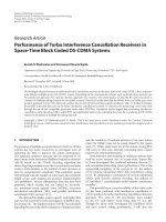
2.1.1 MIMO Communication System
We consider a MIMO system with M
T
transmit and N
R
receive antennas as shown
in Figure 2.1.
The transmitted signal at time p is represented by an 1 × M
T
row vector S =
[s
p1
, s
p2
, . . . , s
pM
T
]. The total transmitted power is constrained to E
0
, regardless of the
11
CHAPTER 2. MIMO COMMUNICATION SYSTEMS IN WIRELESS FADING CHANNELS
Fig. 2.1: Wireless link with M
T
transmitter and N
R
receiver antennas. Every receiver antenna is con-
nected to every transmitter antenna through an independent, random, unknown propagation
coefficient having Rayleigh distributed magnitude and uniformly distributed phase. Normal-
ization ensures that the total expected transmitted power is independent of M
T
for a fixed
ρ
number of transmit antennas M
T
. This power constraint gives
E
M
T
i=1
|s
pi
|
2
= E
0
. (2.1)
If we assume that the signals transmitted from individual transmit antennas have
equal power, then the power from each single transmit antenna is given by E
0
/M
T
.
The transmitted signal bandwidth is narrow enough, so its frequency response can
be considered as flat.
The channel is described by an M
T
× N
R
complex matrix, denoted by H, whose
element h
il
represents the propagation coefficient between the i-th transmit antenna and
the l-th receive antenna. For normalization purposes we assume that the received power
for each of the N
R
receive antennas is equal to the total transmitted power, i.e., E
0
.
12