Approaches for efficient tool condition monitoring based on support vector machine
Bạn đang xem bản rút gọn của tài liệu. Xem và tải ngay bản đầy đủ của tài liệu tại đây (1.12 MB, 147 trang )
Chapter 1 Introduction
1
CHAPTER 1
Introduction
1.1 Research background
One of the most important trends in modern manufacturing systems has been the
relentless efforts towards minimizing the cost, maximizing productivity and
improving product quality. Tool condition sensing greatly contributes towards the
optimization of the cutting process, efficient tool change policies, improvement on
product quality, and reducing tool cost (Kumar et al., 1997). Thus tool condition
monitoring (TCM) is critical in manufacturing systems.
The major objective of a sensor-based TCM system is to determine the cutting tool
conditions (such as tool wear, breakage etc.) from the sensor data. Much research
(Elbestawi et al., 1991; Dornfeld, 1990; Tansel and McLauglin, 1993; Wong et al.,
1997) has been undertaken in these fields, since cutting tools are both an important
factor in manufacturing costs and the quality of the workpiece (Pfeifer and Wiegers,
2000). Despite intensive research during the past two decades, successful and
effective TCM in automated machining systems remains an engineering challenge (Li
and Mathew, 1990). The developed systems often have narrow ranges of
performance, require substantial training or setup time to function correctly (Byrne
and Dornfeld, 1995). Therefore further research is needed.
In the following section, the basic architecture of sensor-based TCM systems is
Chapter 1 Introduction
2
presented, which includes sensing method, feature extraction and selection, and
decision-making techniques.
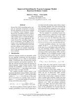
1.2 Architecture of TCM system
TCM System is basically an information flow and processing system (as shown in
Figure 1.1), in which the information source selection and acquisition (sensing data
collection), information processing and refinement (feature extraction and selection)
and decision making based on the refined information (condition identification) are
fully integrated.
Figure 1.1 Information flow and processing scheme in TCM
1.2.1 Signal acquisition by sensing methods
Sensing is the first part of the information-driven TCM system, which provides the
primary information inputs. The basic requirements in the selection of sensing signals
are:
1. The signals should directly or indirectly provide information that is closely
related to the changes in the tool conditions.
2. The signals should have high signal to noise ratio (SNR), and not interfere with
the machining process.
3. The acquired sensing information should indicate or detect all significant events
in the cutting process.
1.2.2 Signal processing
Signal processing is the core function of the information-driven TCM system,
Tool Condition
Signal Selection and
Acquisition
Information Processing
and Refinement
Decision
Making
Chapter 1 Introduction
3
which includes feature extraction and feature selection. It basically performs a
transformation process in which a large flow of sensor signals is streamlined to a
compact tool-condition-informative feature vector in time and frequency domain. The
key challenge in this technique is to derive features, which contain not only as much
tool condition information as possible, but also compact in nature.
Feature extraction
Since sensed signals are typically noisy, these signals have to be further processed
i.e. feature extraction, to yield useful features that are highly sensitive to tool
conditions. The widely used feature extraction approaches include:
1. Time domain analysis such as derivative of signal (Li and Mathew, 1990),
statistical value of waveform (Kannatey-Asibu and Dornfeld, 1982).
2. Advanced signal processing techniques such as neural network (Tansel and
McLauglin, 1993), wavelet analysis (Tansel and McLauglin, 1993, Wu and Du, 1995).
3. Power spectrum analysis such as FFT, cross spectrum (Emel and Kannatey-
Asibul, 1988).
4. Time series analysis, such as autoregressive (AR) and autoregressive moving
average (ARMA) (Liang and Dornfeld, 1989).
Feature selection
Feature selection is to select an optimum subset of features from potentially useful
features which are available in a given problem domain (Gose et al., 1996). It is a
challenging task to select the characteristic features that not only represent the
characteristics of the process (information), but also contains less noise. This method
outputs a subset of all available features, therefore, the dimensionality of the final
input feature set may be reduced. Its intention is not only to discover all the features
Chapter 1 Introduction
4
relevant to the concept and determine how relevant they are, but also to find a
minimum feature subset for effective classification with good generalization
performance. In addition, feature selection may also speed up the classifier for time
critical applications, and make feature discovery possible.
The optimum feature subset has been defined as the subset that performs the best
under a classification system (Jain and Zongker, 1997). "Performs the best" here may
be explained in two slightly different ways:
1. The subset of features which gives the lowest classification error (an
unconstrained combinatorial optimization problem); or
2. The smallest subset of features for which the classification error proportion is
below a set threshold (constrained combinatorial optimization) (Siedlecki and
Sklansky, 1988).
The latter is widely employed in many practical applications including this
research.
1.2.3 Decision making
The decision-making strategy is to map the signal features to a proper class
(machining tool conditions) i.e. pattern recognition (Li and Mathew, 1990). The
output of the decision-making process includes one or more of the following:
1. Identification of tool conditions (such as tool wear/breakage etc.).
2. Evaluation of the severity of certain abnormal tool conditions.
3. Prediction of tool conditions and control of machining process.
This research focuses on the first item, i.e. binary tool conditions identification
(fresh or worn) and multiclassification of tool conditions (sharp, workable and worn).
The robustness of decision-making depends not only on the identification techniques,
Chapter 1 Introduction
5
but also on the features’ quality. The better the inter-class separation capability of the
features, the more robust the identification results will be.
1.3 Literature review
Tool wear in the metal cutting process results in a loss in dimensional accuracy of
the finished product and some possible damage to the work-piece. With the increasing
use of machining centers and flexible manufacturing systems, on-line tool wear
monitoring has become a challenging research field. The following session provides a
comprehensive review about every component of the above mentioned scheme.
1.3.1 Overview of sensing method
To achieve greater reliability and robustness in turning operation, both single and
multiple sensing, coupled with various signal processing and pattern recognition
techniques, have been investigated for single or multiple tool condition identification.
As aforementioned, the potentially most economical scheme for TCM is to employ a
single-sensor approach for multiple tool conditions identification from the viewpoint
of information utilization.
The sensing methods in TCM can be categorized into direct or indirect methods
according to the signal obtained (Micheletti et al., 1976). The direct sensing method
estimates tool conditions through the measurement of tool geometry directly, such as
shape or position of cutting edge, optical scanning of the tool tip, electrical
measurement of the contact resistance between the tool and workpiece, and
radioactive analysis of the chip, analyzing the vision of the tool, measuring the
volume of wear particles or the distance between workpiece and tool or tool holder.
The limitation of these methods lies in that it is difficult to collect the relevant
Chapter 1 Introduction
6
information under actual cutting process.
The indirect methods are those concerned with detecting some process-borne
signals about tool wear and establishing the relationship between these signals and
tool wear (Elbestawi et al., 1991). Indirect methods include measurement of cutting
force (Elbestawi et al., 1991; Hong et al., 1996; Santanu et al., 1996; Bao and Tansel,
2000), acoustic emission (Diei and Dornfield, 1987; Sampath and Vajpayee, 1987;
Liu and Liang, 1991; Zizka, 1996; Wilcox et al., 1997; Niu et al., 1998; Xu, 2001),
vibration of tool or tool post (Lee et al., 1987; Elwardany et al., 1996; Moore and Kiss,
1996; Li and Dong, 2000), ultrasonic vibration (Ultrasonic Energy) (Hayashi et al.,
1988; Coker and Shin, 1996; Abuzahra and Yu, 2000), acoustic wave (sound) (Takata
et al., 1986), current of spindle or feed motor (power input) (Matsushima et al., 1982;
Rangwala and Dornfeld, 1987; Altintas, 1992; Lee et al., 1995) and optical signal
(Cuppini et al., 1986; Oguamanam et al., 1994; Wong et al., 1997). These indirect
methods have the advantages of less complexity and suitability for practical
application (Byrne and Dornfeld, 1995), thus they have been used by many
researchers. Of all the signals, acoustic emission (AE), and cutting force are most
commonly used. An introduction about them is provided as follows.
AE sensing
AE signals reflect the microscopic activities (friction, fracture etc.) of the cutting
process. It naturally contains multiple tool condition information such as tool wear,
fracture etc. Through proper processing, it can be more economically (compared with
multi-sensing approach) used for multiple tool condition identification. The merit of
using AE to detect tool wear lies in its frequency range is much higher than that of the
machine vibrations and environment noises (Sata et al., 1973). Hence, relatively
precise signal can easily be obtained by applying high-pass filter. Moreover, AE can
Chapter 1 Introduction
7
be obtained by using a piezoelectric transducer mounted on the tool holder which
does not interfere with the cutting operation, thereby makes continuous monitoring
tool condition possible. However, other researchers held a different idea. They
believed that AE signals cannot be independently used to provide reliable tool wear
detection in TCM. Blum and Inasaki (1990) performed experiments to determine the
relationship between flank wear and AE signals. They were particularly interested in
the use of the AE mode, a parameter describing the ‘whole’ characteristics of the
cutting process, and then concluded that extracting tool wear information from the AE
signal was difficult. The reason causing the two opposing views did not lay on the
sensing technology, but on the ensuing analysis (Lister, 1993). Based on this opinion,
this thesis first discusses the application of AE signals in TCM system when steel is
used as workpiece.
Cutting force sensing
Measuring cutting forces is one of the most common techniques to monitor tool
condition, since they are more sensitive to tool wear than vibration or power
measurements (Lee et al., 1989). The reliability of force measurements is another
factor for their popularity in tool wear monitoring applications.
As a cutting tool shears the workpiece, high stresses and strain rates give rise to
forces with dynamic behavior across a broad spectrum of frequencies. The
relationship between tool wear (e.g. flank wear and crater wear) and increasing
cutting force is well known for a long time (Dornfeld, 1990; Oraby and Hayhurst,
1991; Lee et al, 1992; Ravindra et al., 1993b; Tarng et al., 1994).
Although many investigators agreed that the change of cutting forces represents an
accurate and reliable approach to estimate tool condition, they still argued which
component is the most sensitive; dynamic component, static component, or both of
Chapter 1 Introduction
8
them. Cutting condition is also an argued issue. Cuppini et al. (1990) implemented a
continuous monitoring method and established relationships between wear and cutting
power without cutting conditions. While, Choudhury and Kishore (2000) believed
that cutting speed, feed and depth of cut should be taken into account in tool
condition recognition.
This work has tried to clear up the above arguments according to cutting force
from titanium machining.
1.3.2 Overview of signal processing
AE signal processing
Due to AE signals’ high frequency nature and sensitivity to the micro-structural
behavior of material, it is widely employed to extract the useful information in TCM.
Iwata and Moriwaki (1977) pioneered the method of using AE signals to monitor
tool wear condition in a cutting process, and they found that the power of spectrum of
AE signals up to 350kHz increased with tool wear and then it reached saturation.
Since the AE signal associated with the tool flank wear is stationary in nature, fast
fourier transform (FFT) is still the best tool for the analysis of this type of signals. The
spectral density of AE signals has been found to be the most informative feature for
TCM in turning (Emel and Kannatey-Asibu, 1988). Naerheim and Arora (1984) used
continuous and discontinuous AE in turning operations to test gradual wear and
intermittent degradation of cutting tools, respectively. Roget et al (1988) concluded
that AE parameters such as root mean square (RMS), mean, and peak values and their
corresponding variance, kurtosis and skew could provide sufficient warning
information of tool breakage and tool wear in various cutting condition. Jemielniak
and Otman (1988) considered that the skew and kurtosis to be better indicators of tool
Chapter 1 Introduction
9
failure than RMS values. Another approach for improving the reliability of the wear
related AE signal was proposed by Blum and Suzuki (1988). A feature called “AE
mode” has been observed to be quite sensitive to tool wear condition. Time series
analysis focuses on the stochastic nature in the dynamics process of AE generation.
Liang and Dornfeld (1989) employed time series modeling techniques to extract AE
features such as autoregressive (AR) parameters and AR residual signals for testing
and monitoring tool wear. Moriwaki and Tobito (1990) proposed statistical features
(mean, variance and the coefficient of RMS) as inputs of a pattern recognition system
to identify and predict the ensuing tool life for coated tool life estimation. Zheng et al.
(1992) used an optic fiber sensor and a commercially available PZT AE sensor to
conduct drilling and milling operations. Results from the two experiments showed a
reasonable degree of agreement. Using AE features, König et al. (1992) performed
tests to monitor small drillings and detect tool fracture, and reported that AE features
were sensitive to tool chipping. Dornfeld (1992) presented compelling reviews on the
application of AE sensing techniques in tool wear detection in machining. He
observed that the changes in skew and kurtosis of AE RMS signals could effectively
indicate tool wear. Kakade et al. (1994) reported that AE parameters (ring-down count,
rise time, event duration, event rate and frequency) could distinguish clearly the
cutting action of a sharp and worn or broken tool. Kannatey-Asibu and Dornfeld
(1982) found that the changes in skew, kurtosis and of the AE RMS signal effectively
indicate the tool wear in machining. Kamarthi et al. (1995) considered that AE
features extracted by the wavelet transform were very sensitive to gradually
increasing flank wear. The magnitude of the AE in the frequency domain was
employed by Li and Yuan (1998) to monitor the change of tool states. Choi et al.
(1999) fused AE and cutting forces to develop a real-time TCM for turning operations.
Chapter 1 Introduction
10
The recorded data were analyzed through a fast block-averaging algorithm for
features and patterns indicative of tool fracture. Similar work was conducted by
Jemielniak and Otman (1998), who used a statistical signal-processing algorithm to
identify RMS, skew and kurtosis of the AE signals and detect catastrophic tool failure.
Inspection of the results indicated that the skew and kurtosis were better indicators of
catastrophic tool failure than the RMS values.
Cutting force processing
Shi and Ramalingam (1990) investigated the feasibility of different force
components, and observed that the feed force to cutting force ratio was sensitive to
flank wear but insensitive to process changes (cutting speed and depth of cut).
Dornfeld (1990) and Ko and Cho (1994) focused on the dynamic characteristic of the
cutting force, due to the friction variation between tool and workpiece in tool wear
process. Oraby and Hayhurst (1991) developed a model to build the relationship
between the feed force, radial force and flank wear in a turning operation. Elbestawi
et al. (1991) employed FFT to compute the sensitivity of cutting harmonics (cutting
force signals) to flank wear. Lee et al. (1992) found that the components of feed and
tangential dynamic force bore a good relationship to flank wear trend. Lister (1993)
analyzed the power spectra of dynamic cutting forces and found that the power level
of certain frequency band increases with tool wear. In the orthogonal milling, Caprino
et al. (1996) concluded that both the horizontal and vertical forces undergo large
variations with tool wear. Lee et al. (1989) analyzed the dynamic force signals of a
coated grooved tool by FFT, and found that the percentage increase of dynamic
tangential force could give a promising threshold for the prediction of tool failure.
Choudhury and Kishore (2000) observed that the ratio between the feed force and
cutting force provided a practical method to quantify tool wear in turning. Dimla and
Chapter 1 Introduction
11
Lister (2000b) reported that both static and dynamic cutting forces were effective in
TCM. The former was the most sensitive to cutting condition changes, while the latter
was good at tracking changes of tool wear. He also observed the vertical components
(z-direction) of both cutting forces and the vibration were the most sensitive to tool
wear. Generally, investigators agreed that the cutting forces could provide a good and
reliable indication of tool conditions, although differed in the relative effectiveness of
cutting force components.
From the above review, both AE and cutting force are widely used in TCM and
different extracted features from them are preferred in their individual TCM systems.
However, neither has been shown to always provide better identification performance
than the other. Also, features collected from the independent data sources are not
equally informative as certain features may correspond to noise, not information;
others may be correlated or not relevant for the task to realize, since any technical
indicators and statistical information related to the tool state can also be used as the
predictors. Furthermore, the success of a decision making method depends largely
upon how well the monitoring features describe the characteristics of the process
conditions. Thus, selecting a suitable feature set is the critical factor in TCM.
1.3.3 Overview of decision making
The methods employed in this field can be classified into three categories: model-
based method, statistical-stochastic method and artificial intelligence approach.
Model-based method
Model-based method sometimes can be viewed as heuristic-based rules with
apriori knowledge only of the process parameters (Dimla and Lister, 2000b), e.g.
Chapter 1 Introduction
12
cutting time, feed rate, cutting speed, temperature, depth of cut, rake angle, material
property and cutting force.
Koren and Lenz (1978) developed a physical model of cutting tool flank wear by
using linear control theory. Assuming this flank wear consists of a mechanically and
thermally activated component, the model yielded a new tool-life equation which is
valid over a wider range of speed than Taylor tool-life equation. Kramer (1980)
identified the mechanism by controlling the crater wear in the high speed cutting of
steel. A simple model, for the first time, has been developed to describe the wear
process from thermodynamic properties of the tool-work system. With the use of AE
signals, Liang and Dornfeld (1989) developed an AR time series model to classify
cutting tool conditions. AR parameters in a predefined function form could be
adaptively modified with a stochastic gradient algorithm, so as to provide correlation
information. Danai and Ulsoy (1987) developed a linearized version of Koren and
Lenz’s flank wear model (1972) so as to separate the effects of cutting conditions on
measured force. Lin et al. (1996) built a regression model based on experimental data
to estimate tool wear, which is a function of average chip thickness, tooth number,
normal force coefficient and friction force coefficient. Abuzahra and Yu (2000)
presented the relation between the acoustic behavior of ultrasound waves and the
progressive tool wear in a mathematical form. In high speed cutting processes,
Molinari and Nouari (2002) modeled the diffusion wear so as to optimize the cutting
processes in terms of tool life.
However, all of these methods suffer from two significant limitations in industrial
applications. First, machining process is a non-linear time-variant system, which is
difficult to model and correlate the actual tool status with the physical variables from
monitoring system. And secondly, the signals obtained from sensing are dependent on
Chapter 1 Introduction
13
machining conditions. Thus, it is rather difficult to identify whether a change in
signals is due to the variation of cutting conditions or tool wearing process. Therefore,
it is impossible to obtain an accurate result only by the single signal analysis.
Statistical-stochastic method
Sensor signals under this method are assumed to have a probabilistic distribution in
time or frequency domain so that one can extract useful information from statistical
distribution.
Houshmand et al. (1991) implemented linear and quadratic discriminate analysis of
multivariate AR processes in AE spectral components. Li et al. (1999) used the AE
and feed current signals to detect tool breakage by discrete wavelet transform. In
order to predict tool state, the envelope detection method is employed to calculate the
second difference of each wavelet coefficient for comparison with the tolerance
threshold.
Nevertheless, their research produced good results in certain limited experimental
situations. First the prior assumption and its threshold scheme make the system
sensitive to the different tool-machine-workpiece combination, which restrict its
applications. Then, the limitation of the inherent complexity in tool-wear tribology
and its variability over numerous cutting conditions make this method far from
practical and reliable. Recently, these strategies have been widely integrated with
artificial intelligence as the signal interpretation method.
Artificial intelligence approach
The emergence of artificial intelligence techniques has seen their enormous
applications to TCM system, such as simple decision logic (Rao, 1986; Altintas,
1992; Elbestawi et al., 1991; Wu and Du, 1996), pattern recognition (Hirotoshi et al.,
Chapter 1 Introduction
14
1993; Diniz et al., 1992; Ravindra et al., 1993a; Colgan et al., 1994), fuzzy logic (Li
and Elbestawi, 1996a), wavelets (Du, 1995a; Niu, 1998), and NNs (Rangwala and
Dorneld, 1990; Chryssolouris, 1992; Tansel and McLauglin, 1993b). Among them,
neural networks (NNs) are the most popular and successful tools.
There is extensive literature about the application of NNs in this field (Rangwala
and Dornfeld, 1987; Dornfeld, 1992; Tarng et al., 1994; Hong et al., 1996; Tansel,
1993; Santanu et al., 1996; Wong et al., 1997; Niu et al., 1998; Xu, 2001).
In NNs’ learning process, synaptic weights can be adjusted in an interactive
process. In terms of this character, the learned knowledge is usually distributed over a
large number of neurons, and can be retrieved almost instantaneously in practical
application. NNs can also perform decision making based on incomplete and noisy
information, which makes it suitable for the diagnostic function in a manufacturing
system (Rangwala and Dornfeld, 1990).
Rangwala and Dornfeld (1987) pioneered the use of Back-propagation (BP) to
classify AE and force signal for tool wear monitoring. Up to 97% reliability was
achieved in identifying the worn state of a turning tool. In order to compare the
learning abilities, Chryssolouris (1992) simulated tool wear monitoring using both
statistical fusion approaches and BP method. Their results have shown that neural
network is superior to statistical fusion approach in TCM. Using AE and cutting force
signal, Leem and Dornfeld (1995) designed a customized neural network for sensor
fusion in on-line detection and achieved high accuracy rates with robustness in
classifying tool wear to two and three levels. After tool wear levels were topologically
ordered by Kohonen’s Feature Map, input features of AE and force were transformed
via input feature scaling. Niu et al. (1998) applied a local wavelet packet
decomposition method to analyze AE signals in turning process, and separated the
Chapter 1 Introduction
15
signals into transient and continuous components. To identify tool wear status, six
features (mean and standard deviation of skew, kurtosis and bandpower) from spectral
and statistical analysis techniques were used as inputs to adaptive resonance theory
(ART2) network. Silva et al. (1998) developed two types of NNs (self-organizing map
(SOM) and ART2) to classify tool wear in terms of 15 features collected from five
sensors. In order to improve the two networks’ performance, an expert system on the
basis of Taylor’s tool life equation was used to identify and eliminate outlier. Li et al.
(2000) implemented the Multiple Principal Component (MPC) and Fuzzy Neural
Network (FNN) for TCM. Force, vibration, and spindle motor power signals were
fused in MPC to give a highly sensitive feature space, and the flexible structure of
decision tree and the uncertainty measurement of fuzzy logic were utilized to perform
decision making.
Xu (2001) applied Radial-Basis Function (RBF) network to perform
real time monitoring of tool wear, in which an unsupervised Kohonen map was used
to select self-organized centers.
Despite some successful applications and satisfactory characteristics, these
algorithms also have their weaknesses such as a large number of controlling
parameters, generalization problem (over-fitting problem, local minima). For instance,
BP learning algorithm susceptibly stays in local minima and converges slowly in
large-size problems. Unfortunately, both AE data and cutting force data in TCM are
complex and involve large flow of information. Due to the use of clustering theory
and empirical risk minimization, RBF usually suffers from the low generalization
performance and demanding computational task on testing samples (Zhang, 2002).
Since no prior knowledge of tool wear is utilized in unsupervised algorithms such as
ART2, these algorithms impose a great challenge for feature extraction techniques
(Niu et al., 1998). However, extracting compact tool-wear-sensitive but condition-
Chapter 1 Introduction
16
independent features is still an ongoing research issue.
In this thesis, support vector machine (SVM) is proposed to learn the correct tool
wear information in the extensive cutting conditions. Compared with other learning
algorithms, the SVM possesses a firm background and excellent features, such as
minimizing the system complexity, yielding a significant gain in classification
accuracy.
In conclusion, most TCM methods employ indirect sensing which generally
reflects certain physical characteristics of the cutting process. The needs for
reasonable on-line TCM demand high requirements on the efficiency of feature
extraction techniques. This refers to using the minimal computation task to derive the
most complete informative tool-condition correlated features. NNs based on
knowledge learning and prediction is the most popular method to perform decision
making on tool conditions. These issues are further discussed in great details in the
following chapters.
The value of this research is to improve the application of NNs-based methods in
TCM so as to realize reliable tool condition identification over a range of cutting
conditions.
1.4 Research objective and contributions
The objective of this work is to improve tool condition identification so as to
achieve efficient and reliable TCM for industrial applications. It integrates the above
mentioned research progress and identifies the key problems in applying NNs to
TCM.
In a TCM system, various features from suitably processed sensing signals are
Chapter 1 Introduction
17
utilized by researchers. However, not every feature is equally informative in a specific
monitoring system. Hence, the issue of feature selection is discussed, and a method is
introduced to identify important features.
When NNs are utilized to identify tool states in machining processes, the main
interest is often on the recognition ability. Nevertheless, a higher classification rate
from pattern recognition does not agree with the lower manufacturing loss in practical
manufacturing systems. Thus, a new evaluation function is proposed by
manufacturing loss consideration so that the recognition ability of TCM can be
considered by accounting for the economic impact more reasonably. A nonstandard
NN method is then utilized to perform the recognition task.
In metal cutting, there is a different between rough cutting and finish cutting. In
rough cutting, the main consideration is to effectively remove material to shape that is
close the desired dimension. In such process, the surface roughness is not important.
In contrast, finishing cut requires precise cutting and stringent surface roughness
requirement. These imply that the wear limit for roughing and finishing is different,
and the latter is usually less than that of the former. In other words, a worn tool in
finishing could still be used in roughing. Hence, there is a need to differentiate
different category of tool wear conditions. Therefore this tool condition identification
method is extended to multiclassifying tool conditions. Finally, a framework which
generalizes sensing signal selection, feature analysis, performance evaluation and
decision making is proposed in this study. Two case studies are provided to
demonstrate the above proposed methods: one based on AE signal from machining
steel and the other based on cutting force from machining titanium.
In short, the major contributions of this thesis include:
(1) Develop a method to identify feature set from various extracted features.
Chapter 1 Introduction
18
(2) Propose a new performance evaluation function by manufacturing loss
consideration.
(3) Propose an effective decision making method in tool condition identification.
(4) Improve the performances of binary and multilevel tool condition identification
by reducing potential manufacturing loss.
(5) Suggest a procedure to select an effective training data set in TCM system.
(6) Propose a framework to generalize sensing signal selection, feature analysis,
performance evaluation and decision making.
1.5 Organization of thesis
Chapter 1 gives a literature review of TCM scheme. First, the importance of TCM
in unmanned manufacturing system is introduced; then the basic components of TCM
sensing method, signal processing and decision making) are described; finally a detail
literature review about them is presented.
Chapter 2 introduces four kinds of tool wear mechanisms (abrasive wear, adhesive
wear, diffusion wear, fatigue wear), two types of tool wear according to the wear
position (flank wear, crater wear), tool life and its criteria. The generation of AE and
cutting force signals from a tool wearing process are also discussed.
The experimental setup is introduced in chapter 3, followed by the design of
experiment. A detail introduction about the AE sensing, cutting force sensing, tool
inserts and workpieces used in this study is presented. In the design of experiment,
three levels of cutting speed and feed, and two levels of workpiece and cutting depth
are selected in the provided case study. Therefore, only nine experiments are needed
to study the entire machining parameter space using L9 orthogonal array.
Chapter 1 Introduction
19
In chapter 4, an intelligent feature analysis method, which integrates feature
extraction and feature selection, and decision making was designed and implemented.
This study comprehensively takes all these known signal features and aims to identify
the most effective set that can give robust and reliable identification of tool condition.
Automatic relevance determination (ARD) approach coupled with SVM is employed
to rank these features, prune redundant information so as to realize effective
identification of tool flank wear. This method can not only reduce the data processing
requirement as fewer feature sets are involved, but also provide robust and feasible
recognition in an efficient way. AE from machining steel is utilized as sensing signals
and the commonly extracted AE features are adapted to discuss this subject.
Chapter 5 firstly discusses the existing problems when NNs and related methods
are used to classify tool conditions. Then two kinds of losses caused by misclassifying
tool states are analyzed: one is using a worn tool to machine workpiece; the other is
the early replacement of a workable tool. Based on the relationship of two kinds of
losses, a new evaluation performance is proposed as the criterion to evaluate the
recognition performance of TCM system. Finally, a modified SVM approach with
two regularization parameters is employed which can adjust the recognition ability for
each tool condition separately. Experimental results show the proposed approach can
reduce the overdue prediction and lower potential manufacturing cost. The following
topics are also involved: generalization performance, evaluation criteria, training data
selection and parameters tuning in tool condition identification. An effective training
data selection procedure is proposed in this chapter, which leads to a considerable
reduction in the necessary training samples without the loss of classification
performance. Experimental results also show that this selection strategy can provide
Chapter 1 Introduction
20
an effective training data set with reliable recognition performance in tool condition
identification.
The benefits of multiclassification of tool wear are described in chapter 6. The
problems that existed in the application of NNs in TCM are analyzed, and the
performance evaluation function introduced in chapter 5 is extended to multilevel
classification of tool condition. Finally three binary revised SVM classifiers in total
are utilized to perform the multiclassification of tool conditions regarding AE features
and the cutting parameters.
Chapter 7 presents a framework to generalize sensor signal selection, feature analysis,
performance evaluation and decision making in TCM system. The application of this
framework for candidate signals (AE and cutting force) in titanium machining is
discussed. Firstly, three basic requirements to sensor signals are proposed, and feature
analysis is utilized to select the most effective feature set to identify tool conditions.
From the analyzed results, cutting force sensing is considered as a suitable monitoring
signal, and its effective feature set is used as input for tool condition identification in
titanium machining. Then, a performance evaluation function with manufacturing loss
consideration is introduced to determine whether a tool is due for replacement other
than merely the extent of wear of the cutting tool. Finally, a modified SVM algorithm
is utilized to minimize this evaluation function. Experimental results demonstrate that
this study provides an effective and reliable framework to implement tool condition
identification in titanium machining. It can also be exploited to monitor other cutting
processes.
Conclusions are given in chapter 8 together with recommendation for future
research.
Chapter 2 Tool Wear and Sensing Signals
21
CHAPTER 2
Tool Wear and Tool life
2.1 Tool wear mechanism
In order to achieve an economical tool life, various tool angles, cutting speeds, and
feed rates are adopted in metal cutting. However, the accurate tool life estimation is
considered more important in improving the productivity of computer-integrated
machining systems (Kramer, 1986). In practical machining processes, because of the
non-homogeneities in both tool material and workpiece, not only uniform wear but
also other unexpected wear states can be observed (e.g. breakage, chipping). In order
to estimate tool state accurately, the fundamental forms of tool wear mechanism and
tool failure are introduced.
The basic mechanisms of tool wear are controlled by the cutting conditions
(cutting speed, feed rate, etc), the mechanical and physico-chemical properties of the
work piece and tool. Tool wear is also the result of load, friction, and high
temperature between the cutting edge and the workpiece. In the following section,
some major forms of tool wear mechanism are described, such as abrasion, adhesion,
diffusion and fatigue.
Abrasive wear is a primary wear mechanism in metal cutting. Debris, which is
created by plastic deformation, enters the clearance space between two moving
surfaces and acts like cutting tools to remove materials from the surface. Friction
between the chips and the cutting edge leads to the formation of build-up edge. When
Chapter 2 Tool Wear and Sensing Signals
22
this edge reaches an unstable size, it breaks away in small pieces or fracture (in the
latter case, it causes damage to the cutting tool – adhesive wear). The ability of
cutting edge to resist abrasive wear is related to its hardness.
Adhesive wear occurs mainly at low temperature. Excessive load and low speed
often reduce the oil film thickness to a point where intimate metal-to-metal contact
occurs, thus adhesive wear is formed.
Diffusion wear mainly affected by chemical factors during the cutting process, is
characterized by the smooth worn surface without plastic deformation. It is produced
when the tool or more specifically the atoms on its surface are diffused and are carried
away in the form of chips. The material transfer towards the chip eventually leads to
the forming of a crater on the tool rake face. Generally, higher temperature may result
in faster tool wear.
Fatigue wear occurs as continuous sliding, rolling, impacting motions subject a
surface to repeat stress cycling. The stress cycle starts with small cracks on or near the
surface, and then the cracks eventually become large enough to cause discrete regions
near the surface to be ejected as debris. Leading causes of fatigue wear include
insufficient lubrication, lubricant contamination, and component fatigue.
2.2 Tool wear and tool life
2.2.1 Tool wear
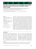
In this section, two types of tool wear according to the wear position are introduced:
flank wear and crater wear. Figure 2.1 shows a typical demonstration of flank wear
and crater wear at the cutting edge. This kind of classified visual angles is used
throughout the whole thesis.
In a normal machining process, the motion of the tool’s flank face against the
Chapter 2 Tool Wear and Sensing Signals
23
surface of the workpiece causes a “wear land” on the flank of the cutting tool, named
flank wear. Flank wear, resulting from the combined effect of abrasive wear and
adhesive wear, is found to increase steadily with cutting time and speed. When tools
are used under economical conditions, the flank wear is usually the controlling factor
(Boothroyd and Knight, 1989).
Figure 2.1 Typical demonstration of tool wear
(Boothroyd and Knight, 1989)
Crater wear caused by a chemical interaction between the hot chip, workpiece and
material, is characterized by a concave wear pattern on the rake surface of an insert.
Under high-speed cutting conditions, crater wear is often the key factor to determine
the life of a cutting tool. Excessive crater wear weakens the cutting edge, inhibits
proper chip flow, increases heat and pressure on the tool and eventually leads to tool
fracture. The crater depth KT is the most commonly used parameter in evaluating the
rake face wear, KB and KM are the crater width, crater centre distance, respectively.
Both flank wear and crater wear belong to gradual wear, while chipping and
breakage are two kinds of catastrophic wear. Chipping happens when the edge line
Chapter 2 Tool Wear and Sensing Signals
24
breaks away from a tool’s cutting edge, rather than wear. The chipped pieces may be
very small, or relatively large. Intermittent cutting and thermal fatigue are key reasons
of chipping, meanwhile gross inconsistencies in the workpiece material composition
or structure may also cause chipping.
2.2.2 Tool life
ISO 3685 (International Standard, 1993) defines tool life as the time elapsed until a
defined amount of wear has occurred in the rake face or flank face of the cutting tool.
When a tool is used under normal cutting conditions, flank wear is usually the
primary factor that determines the life of an insert, while crater formation is more
important under high-temperature and high speed cutting conditions (Boothroyd and
Knight, 1989). In this experiment, due to cutting conditions within the normal range,
only flank wear is considered to determine tool life. This is also because of the more
direct influence that flank wear has on the accuracy of the product.
In practical machining operations the flank wear is not uniform along the active
cutting edge; therefore it is necessary to specify the locations and degree of the wear.
As shown in Figure 2.1, on the active cutting edge, the flank wear at the tool corner
tends to be more severe than that in the central part, because of the complicated flow
of chip material in that region. The width of the flank wear land at the tool corner
(zone C) is designated as VC. At the opposite end of the active cutting edge (zone N)
a wear notch often forms, because the workpiece tends to be work-hardened from the
previous processing operation in this region. The width of the wear land at the wear
notch is designated as VN.
In the central portion (zone B), the wear land is fairly uniform. The average wear-
land width in this region is designated as VB or V
B
, and the maximum wear-land is
Chapter 2 Tool Wear and Sensing Signals
25
designated as VB
max
.
The criteria recommended by the ISO 3685 for sintered-carbide tools are:
VB=0.3 mm or; VBmax=0.6 mm if the flank is irregularly worn.
2.3 AE signals and tool wear
AE signals which reflect the microscopic activities (friction, fracture etc.) during
cutting processes and naturally contain multiple tool condition information (tool wear,
fracture), have been proven to effective in TCM. Compared with multi-sensing
approach, AE sensing can be more economically. Thus, it is used as references for
developing tool condition identification system.
During metal cutting the workpiece undergoes considerable plastic deformation as
the tool pushes through it. Within the deformation zones, the low amplitude, high
frequency stress wave generated by a rapid release of strain energy is commonly
referred to as AE. Other sources of AE include phase transformations, friction
mechanisms (tool-workpiece contact), crack formation and extension fracture.
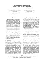
Figure 2.2 Schematic illustration of a two-dimensional cutting process
Figure 2.2 shows a typical orthogonal machining operation. The primary AE source is
the shear zone since shear is accompanied by large scale dislocation motion which
Cutting edge
Workpiec
e
Chip
Rake face
Flank face
Clearance crevice