Design appraisal of steel concrete composite joints
Bạn đang xem bản rút gọn của tài liệu. Xem và tải ngay bản đầy đủ của tài liệu tại đây (4.32 MB, 240 trang )
Founded 1905
DESIGN APPRAISAL
OF
STEEL-CONCRETE COMPOSITE JOINTS
by
TEO TECK HEONG, B.ENG. (Hons.)
DEPARTMENT OF CIVIL ENGINEERING
A THESIS SUBMITTED
FOR THE DEGREE OF DOCTOR OF PHILOSOPHY
NATIONAL UNIVERSITY of SINGAPORE
2003
ACKNOWLEDGEMENT
The author would like to make use of this opportunity to acknowledge various
individuals for their guidance and encouragement in the course of this research.
Firstly, the author would like to express his appreciation for the constant guidance,
valuable advice, constructive suggestions and encouragement provided by his project
supervisors, Associate Professor J. Y. Richard Liew and Professor N. E. Shanmugam.
Secondly, the help given by technical staff in Concrete and Structural
Laboratory, National University of Singapore in the experimental testing is gratefully
appreciated.
Finally, the author is glad to have the moral support and encouragement given
by his family members, especially his wife, Li Sze. The understanding of his daughter,
Jing Jie, for not being able to keep her company during the course of study, is highly
appreciated. Without them, the author would not have his achievement as it is.
This research project was funded by the National University of Singapore
under the research grant RP-264-000-138-112. The author was offered Research
Assistantship under the grant, which made this study possible.
ii
TABLE OF CONTENTS
TITLE PAGE i
ACKNOWLEDGEMENT ii
TABLE OF CONTENTS iii
LIST OF NOTATION vi
LIST OF FIGURES x
LIST OF TABLES xv
LIST OF ABBREVIATIONS xvi
SUMMARY xvii
CHAPTER 1 INTRODUCTION
1.1 General 1
1.2 Research Objectives and Scope of Research 4
1.3 Structure of the Thesis 5
CHAPTER 2 LITERATURE REVIEW
2.1 Introduction 9
2.2 Joint Studies for Composite Non-Sway Frames 10
2.3 Joint Studies for Composite Sway Frames 23
2.4 Summary 25
CHAPTER 3 EXPERIMENTAL INVESTIGATION
3.1 General 30
3.2 Specimens and Test Set up 30
3.2.1 Phase I – Tests Under Symmetrical Loads 30
3.2.2 Phase II – Tests Under Reversal Loads 33
3.3 Instrumentation 35
3.4 Measurement of Joint Rotation 36
3.4.1 Beam Rotation 37
iii
3.4.2 Column Rotation 37
3.4.3 Panel Zone Rotation 37
3.4.4 Connection Rotation 38
3.4.5 Joint Rotation 39
3.5 Material Properties 39
3.6 Test Results 39
3.6.1 Phase I - Specimens Tested Under Symmetrical Loading 40
3.6.1.1 Specimens SCCB1, SCCB2 and SCCB3 40
3.6.1.2 Specimen SCCB4 44
3.6.1.3 Specimens SCCB5 and SCCB6 46
3.6.2 Phase II - Specimens Tested Under Reversal Loading 49
3.6.2.1 Specimen SJ1 50
3.6.2.2 Specimens CJ1 and CJ2 51
3.6.2.3 Specimen CJ3 53
3.6.2.4 Specimen CJ4 54
3.6.2.5 Specimens CJ5 and CJ6 55
3.6.2.6 Specimen CJ7 56
3.6.3 Discussions and Evaluation of Test Results 57
3.6.3.1 Cyclic Load Behaviour 57
3.6.3.2 Strain Profile in the Steel Beam Section 59
3.6.3.3 Strain Profile in the Concrete Slab 60
3.6.3.4 Panel Zone Response 61
3.6.3.5 Rotation Capacity 62
CHAPTER 4 ANALYTICAL MODELS
4.1 Introduction 107
4.2 Moment Resistance 108
4.3 Tensile Resistance in concrete slab 110
4.3.1 Shear resistance of headed stud connector 110
4.3.2 Tensile resistance of the reinforcement 112
4.4 Compressive Resistance 113
4.4.1 Compressive resistance of the steel beam 113
4.4.2 Compressive resistance of the beam flange 114
4.4.3 Compressive resistance of column web 114
4.5 Negative Moment Capacity 115
4.5.1 PNA in the slab 116
4.5.2 PNA in the steel beam 117
4.6 Positive Moment Capacity 127
4.7 Panel Zone Shear Resistance 131
4.8 Initial Rotational Stiffness 133
4.8.1 Initial rotational stiffness under negative moment 133
4.8.2 Initial rotational stiffness under positive moment 142
iv
4.9 Rotation Capacity 142
4.9.1 Deformation Capacity of Slab Reinforcement 144
4.9.2 Deformation of the shear connector 146
4.9.3 Deformation of plastic compression in the beam 148
4.9.4 Deformation of panel zone due to horizontal shear 148
4.9.5 Rotation capacity of composite joint under positive moment 150
4.10 Comparison with test results 152
CHAPTER 5 JOINT MODELING AND IDEALIZATION FOR
FRAME ANALYSIS
5.1 Introduction 181
5.2 Types of joint models 182
5.2.1 Joint modelling reflecting the actual behaviour
(advanced joint model) 185
5.2.2 Simplified joint modelling (concentrated joint model) 186
5.3 Joint Transformation 186
5.4 Idealization of M-φ curves for frame analysis 191
CHAPTER 6 CONCLUSIONS AND PROPOSALS FOR
FUTURE WORK
6.1 Introduction 200
6.2 Experimental Study 201
6.2.1 Phase I 201
6.2.2 Phase II 202
6.3 Analytical Assessment 203
6.4 Joint Modelling 205
6.5 Future Work 206
LIST OF PUBLICATIONS
208
REFERENCES 210
APPENDIX A PUSH OUT TESTS ON SHEAR
CONNECTOR
219
v
LIST OF NOTATION
a distance from the face of the column to the first shear connector along the
beam, distance from the centre of the load at the tip of the beam to the
column face
A area
A
c
cross sectional area of column
A
r
area of slab reinforcement
A
bolt
tensile area of bolt
A
vc
shear area of column
A
st
area of profile steel sheeting
a
p
throat thickness of weld on end plate
b
j
width of a finite size joint
b
fb
breadth of beam
b
fc
breadth of column
B
ec
effective width of concrete slab
b
eff
effective width
b
eff,wc
effective of column web
b
o
mean width of trough of profiled steel sheeting
c depth of compression stress block measured from top of slab, effective
depth
C
S,Rd
translational stiffness of shear
C
LC,Rd
translational stiffness of compression component at L
C
eq,Lt,Rd
equivalent translational stiffness of tension components at L with an
equivalent lever arm
D
b
depth of beam
D
r
distance from the top of steel section to the centroid of the reinforcement
D
s
depth of slab in compression
D
fc
clear depth of column web
D
fb
clear depth of beam web
D
wb
depth of beam web in compression
D
wbe
effective depth of beam web in compression
d the thickness of the concrete flange
d
c
effective of concrete slab
d
bolt
diameter of bolt
d
stud
diameter of shear stud
vi
e
y
yield displacement
E elastic modulus
E
a
elastic modulus of structural steel
E
bolt
elastic modulus of bolt
E
c
elastic modulus of concrete
E
cm
mean value of secant modulus of concrete
E
r
elastic modulus of reinforcement
F force
F
b
compression resistance of steel beam
F
c,slab
compressive force in concrete slab
F
dc
reduced beam web compression resistance due to web buckling
F
r
tensile resistance of reinforcement
F
s
tensile resistance of composite joint
F
t,slab
tensile resistance in concrete slab
F
bf
resistance of beam flange
F
wc
compression resistance of unstiffened column web
f
ck
compressive strength of concrete cylinder
f
cu
compressive strength of concrete cube
f
ctm
mean tensile strength of concrete
f
y
yield strength
f
yr
yield strength of reinforcement
f
yb
yield strength of beam
f
y,wc
yield strength of column web
f
y.st
yield strength of profiled steel sheeting
f
u,stud
ultimate tensile strength of shear stud
f
u,bolt
ultimate tensile strength of bolt
G shear modulus
h
1
distance between centres of reinforcement and bolt-row nearest to upper
beam flange
h
c
the height of the steel column section
h
p
height of profiled steel sheeting
h
r
lever arm of reinforcement
h
j
height of a finite size joint
h
stud
height of shear stud
vii
I second moment area
I
b
second moment of area of beam
k
i
stiffness coefficient of component i
k
p
, k
t
reduction factor for shear stud
k
sc
, stiffness of shear connector
L
r
length of reinforcement having elongation
L
t
transmission length
M moment
M
r
moment capacity of composite joint
N
s
number of shear stud
N
stud
number shear studs in one ribs at a beam section
P
stud
design shear resistance of welded headed stud with a normal weld collar
P
ri
tensile capacity of bolt-row i
P
Rd
shear resistance of shear stud
P
v
shear resistance of column web
P
RK
the characteristic resistance of a stud
p
stud
pitch of shear stud
r
c
root radius of column
s slip deformation of shear stud
S
j
rotational stiffness
S
j,ini
initial stiffness of composite joint
S
S,Rd
rotational stiffness for shear at S
S
L,Rd
rotational stiffness for shear for connection and load introduction at L
S
SC,Rd
transformed shear stiffness
S
LC,Rd
transformed connection stiffness
t
fb
thickness of beam flange
t
fc
thickness of column flange
t
p
thickness of plate
t
wb
thickness of beam web
t
wc
thickness of column web
V
wc
shear resistance of an unstiffened column web
Z
c
centre of compression
viii
z
o
is the vertical distance between the centroids of the uncracked,
unreinforced concrete flange and the uncracked, unreinforced composite
section calculated using the modular ratio for short term effect, E
a
/E
c
α
stud
coefficient for shear stud
σ
sr1
the stress in the rebar when first crack formed
γ
y
shear strain at first yield
ε value of
y
f/235
ε
y
yield strain of steel
ϖ reduction factor for shear in column web panel
ρ reduction factor for plate buckling, rebar ratio
η reduction factor to concrete slab area due to profiled steel sheeting
β transformation parameter
β
t
factor, 0.4 for short term loading
δ factor, 0.8 for high ductility deformed bar
ν Poisson’s ratio
τ
sm
is the average bond stress along the transmission length
δ
ten
total deformation in the tension zone
δ
comp
total deformation in the compression
δ
s
total deformation in the shear zone
φ
r
the diameter of the rebar
φ
b
beam rotation
φ
col
column rotation
φ
c
rotation capacity of composite end plate joint
φ
z
panel zone rotation
φ
con
connection rotation
φ, φ
j
joint rotation
∆
a
compressive deformation of lower beam flange
∆ε
sr
the increase of strain in rebar at the crack, when crack first occur
∆
us
deformation capacity of the reinforcement
ix
LIST OF FIGURES
Chapter 1
Figure 1.1 Distinction between joint and connection (Nethercot & Zandonini,
1990)
Figure 1.2a Parts of a beam-to-column joint configuration by EC4: Single-sided
configuration (Proposed Annex J, EC4, 1996)
Figure 1.2b Parts of a beam-to-column joint configuration by EC4: Double-sided
configuration (Proposed Annex J, EC4, 1996)
Chapter 2
Figure 2.1 Typical M-φ curves of commonly used steelwork connection
Figure 2.2 Symmetrical and Unsymmetrical/Unbalanced Loadings
Figure 2.3 Reversal of Loading
Figure 2.4a Specimen types tested in University of Minnesota, USA (Leon, 1990)
Single connection monotonic tests.
Figure 2.4b Specimen types tested in University of Minnesota, USA (Leon, 1990)
Single connection cyclic tests
Figure 2.4c Specimen types tested in University of Minnesota, USA (Leon, 1990)
Floor subassemblage tests.
Figure 2.5 Type of joint details tested by Plumier and Schleich (1993)
Chapter 3
Figure 3.1 Phase I – Tests under Symmetrical Loads
Figure 3.2 Phase II – Tests under Reversal Loads
Figure 3.3 Details of Flush end plate used in Phase I tests
Figure 3.4 Cross section of Composite Beam.
Figure 3.5 Details of longitudinal and transverse bars
Figure 3.6a Details of SCCB1, SCCB2 and SCCB3
Figure 3.6b Details of SCCB5
Figure 3.7 Details of SCCB6
Figure 3.8a Details of Doubler plate
Figure 3.8b End plate and haunch connection details in Phase II Specimens.
Figure 3.9 ECCS (1986) loading procedure
x
Figure 3.10 Details of Instrumentation in Phase I specimens
Figure 3.11 Details of Instrumentation in Phase II specimens
Figure 3.12 Definition of lever arm, a
Figure 3.13 Relationships of various joint rotations
Figure 3.14 Diagonal transducer to measure panel zone deformation
Figure 3.15 Measurement of panel zone rotation,
φz
Figure 3.16 Moment Rotation Curves of SCCB1, 2 and 3
Figure 3.17 Crack Pattern of SCCB1
Figure 3.18 View after failure of specimen SCCB1
Figure 3.19 Specimen Braced Against Twisting
Figure 3.20 View after failure of specimen SCCB3
Figure 3.21 Crack Pattern of SCCB2
Figure 3.22 Moment Rotation Curve of SCCB4
Figure 3.23 View after failure of specimen of SCCB4
Figure 3.24 Comparison between SCCB2 and SCCB4
Figure 3.25 Definition of Notation for Encased Composite Column
Figure 3.26 Shear Links and Longitudinal Bars Details of SCCB5
Figure 3.27 Shear Links and Longitudinal Bars Details of SCCB6
Figure 3.28 Moment rotation curve of SCCB5
Figure 3.29a Crack Pattern of SCCB5
Figure 3.29b Comparison of M-
φ Curves of SCCB2 and SCCB5
Figure 3.30 Effective Thickness of concrete in Resisting Compression
Figure 3.31 Comparison between SCCB5 and SCCB6
Figure 3.32a Hysteretic M-
φ
j
Curve of SJ1
Figure 3.32b Hysteretic M-
φ
j
Curve of CJ1
Figure 3.32c Hysteretic M-
φ
j
Curve of CJ2
Figure 3.32d Hysteretic M-
φ
j
Curve of CJ3
Figure 3.32e Hysteretic M-
φ
j
Curve of CJ4
Figure 3.32f Hysteretic M-
φ
j
Curve of CJ5
Figure 3.32g Hysteretic M-
φ
j
Curve of CJ6
Figure 3.32h Hysteretic M-
φ
j
Curve of CJ7
Figure 3.33 Moment versus bolt strain for SJ1
Figure 3.34 View after failure of Specimen SJ1
xi
Figure 3.35 View after bolt fractured
Figure 3.36 Comparison of Moment Rotation Curves between CJ1 and CJ2
Figure 3.37 Moment versus Bolt Strain for the right connection of CJ1
Figure 3.38 Moment versus Bolt Strain for the left connection of CJ1
Figure 3.39 View after failure of Specimen CJ1
Figure 3.40 View after failure of Specimen CJ2
Figure 3.41 Comparison between SJ1 and CJ1
Figure 3.42 Welding Details for Doubler Plate
Figure 3.43 View after failure of Specimen CJ3
Figure 3.44a View after failure of Specimen CJ4
Figure 3.44b Tension crack at the extended end plate of CJ4
Figure 3.45 View after failure of Specimen CJ5
Figure 3.46 View after failure of Specimen CJ6
Figure 3.47 View after failure of Specimen CJ7
Figure 3.48 Reinforcement details and strain gauge positions of the column of
specimen CJ7
Figure 3.49 Panel moment versus strain curve at panel zone (1
st
cycle) for CJ7
Figure 3.49a Strain Profile in the steel Beam of CJ7 under increasing negative
moment
Figure 3.49b Strain Profile in the steel beam of CJ1 under increasing negative
moment
Figure 3.50a Strain profile in the concrete slab of CJ4 with increasing positive
moment
Figure 3.50b Strain profile in the concrete slab of CJ7 with increasing positive
moment
Figure 3.50c Strain profile in the concrete slab of CJ6 with increasing positive
moment
Figure 3.51 Panel moment versus panel distortion for specimens CJ2 and CJ3
Figure 3.52 Lever arm z used for joints under reversal of loading
Figure 3.53 Hysteretic M-
φ
j
curves of SJ1 and CJ2
xii
Chapter 4
Figure 4.1 Force diagram in composite flush end plate connection under negative
moment.
Figure 4.2 Dimensions of profiled steel sheeting
Figure 4.3 Effective section of Class 3 and 4 due to local buckling (EC Codes
Approach)
Figure 4.4 Effective width of column web in compression
Figure 4.5a Flow chart for calculating negative moment capacity
Figure 4.5b Flow chart for calculating negative moment capacity (con’t)
Figure 4.5c Flow chart for calculating negative moment capacity (con’t)
Figure 4.5d Flow chart for calculating negative moment capacity (con’t)
Figure 4.6 Negative moment: PNA in concrete slab
Figure 4.7 Full versus modified plastic distribution of bolt forces
Figure 4.8 Case 1 – PNA in centre of compression beam flange
Figure 4.9 Case 2A - PNA below second bolt row
Figure 4.10 Case 2A - PNA below second bolt-row (Class 3 or 4 section)
Figure 4.11 Case 2B-1 - PNA in second bolt-row
Figure 4.11a Case 2B-1 - PNA in second bolt row (Class 3 or 4 Section)
Figure 4.12 Case 2B-2 - PNA above second bolt row
Figure 4.12a Case 2B-2 - PNA above second bolt row (Class 3 or 4 Section)
Figure 4.13a Force diagram in composite haunch connection under negative moment
(PNA in centre of haunch flange)
Figure 4.13b Force diagram in composite haunch connection under negative moment
(PNA in haunch web)
Figure 4.14 Stress and force distribution under positive moment (a) linear (b) plastic
distribution
Figure 4.14 Force diagram for positive moment (c) PNA in concrete slab
Figure 4.14 Force diagram for positive moment (d) PNA in upper beam flange
Figure 4.15 Definition of m and e
Figure 4.16 Spring model for negative and positive moments
Figure 4.17 Calculation of rotation capacity
Figure 4.18 Tension stiffening: development of strain in concrete and reinforcement
at first cracking (single crack) and at the stabilized crack pattern (CEP-
FIP Model Code, 1990)
xiii
Figure 4.19 Simplified stress-strain relationship of reinforcing steel (CEP-FIP
Model Code, 1990)
Figure 4.20 Trilinear approximation OABD of shear stud (Anderson et al., 2000)
Figure 4.21 Typical shear force-distortion behaviour of joint panel
Figure 4.22a Comparison of experimental and analytical values for SCCB1
Figure 4.22b Comparison of experimental and analytical values for SCCB2
Figure 4.22c Comparison of experimental and analytical values for SCCB3
Figure 4.22d Comparison of experimental and analytical values for SCCB4
Figure 4.22e Comparison of experimental and analytical values for SCCB5
Figure 4.22f Comparison of experimental and analytical values for SCCB6
Figure 4.22g Comparison of experimental and analytical values for SJ1
Figure 4.22h Comparison of experimental and analytical values for CJ1
Figure 4.22i Comparison of experimental and analytical values for CJ2
Figure 4.22j Comparison of experimental and analytical values for CJ3
Figure 4.22k Comparison of experimental and analytical values for CJ4
Figure 4.22l Comparison of experimental and analytical values for CJ5
Figure 4.22m Comparison of experimental and analytical values for CJ6
Figure 4.22n Comparison of experimental and analytical values for CJ7
Chapter 5
Figure 5.1 Types of joint model (COST C1, 1999)
Figure 5.2 Joint modelling – conventional and advanced (COST C1, 1999)
Figure 5.3 The definition of CLS (Huber, 1999)
Figure 5.4 Joint modelling reflecting actual behaviour (COST C1, 1999)
Figure 5.5 Application of joint modelling by finite joint model (COST C1, 1999)
Figure 5.6 Simplified joint modelling (COST C1, 1999)
Figure 5.7 Types of curve idealization (a) full non-linear (b) tri-linear (c) bi-linear
Figure 5.8 Bi-linear curve idealization for CJ1
Appendix A
Figure A1 Typical details of push out test specimens
Figure A2 Test set up for push out test for headed stud
Figure A3 Load slip curve for push out test
xiv
LIST OF TABLES
Chapter 3
Table 3.1 Details of the Specimens in Phase I
Table 3.2 Details of the Specimens in Phase II
Table 3.3 Tensile Test of Structural Steel Members
Table 3.4 Tensile Test of Reinforcement Bars
Table 3.5 Concrete Cube/Cylinder Strength and Young Modulus
Table 3.6 Test Results of Phase I Specimens
Table 3.7 Test Results of Phase II Specimens
Table 3.8 Rotation capacities of Phase I and II specimens
Chapter 4
Table 4.1 Rotations corresponding to 2M
u
/3 and M
u
for Phase II specimens
(positive bending)
Table 4.2 Moment Capacity: Experimental versus analytical (Phase I)
Table 4.3 Initial Rotational Stiffness: Experimental versus analytical (Phase I)
Table 4.4 Predicted and measured rotation capacities of Phase I specimens
Table 4.5 Moment capacity: Experimental versus analytical (Phase II)
Table 4.6 Initial rotational stiffness: Experimental versus analytical (Phase II)
Table 4.7a Predicted and measured rotation capacities of Phase II Specimens
(negative bending)
Table 4.7b Predicted and measured rotation capacities of Phase II Specimens
(positive bending)
Chapter 5
Table 5.1 Values of untransformed and transformed stiffness for Phase I
specimens
Table 5.2 Values of untransformed and transformed stiffness for Phase II
specimens (negative bending)
Table 5.3 Values of untransformed and transformed stiffness for Phase II
specimens (positive bending)
Table 5.4 ψ for various joint types
xv
Appendix A
Table A1 Details of push out test specimens
Table A2 Properties of headed studs
Table A3 Properties of concrete
Table A4 Experimental results of push out tests
LIST OF ABBREVIATIONS
AISC American Institute of Steel Construction
BCSA The British Constructional Steelwork Association Ltd
CEB
Comite Euro-international du Beton (Euro-International Committee for
Concrete
)
COST European Cooperation in the Field of Scientific and Technical Research
EC Eurocode
ECCS European Convention for Constructional Steelwork
FIP
Federation Internationale de la Precontrainte (International
Organization for the development of concrete, prestressing and related
materials and techniques)
MR Moment Resisting
PNA Plastic Neutral Axis
RHS Rectangular Hollow Section
SCI Steel Construction Institute
SGTD Strain Gauge Type Transducer
xvi
SUMMARY
The main objective of this study is to obtain a clear picture of moment
rotational responses of different types of composite joints. The test results have been
used to verify the proposed analytical models. The moment-rotation relationships (M-
φ
j
) obtained by using these models are then incorporated into global frame analysis by
taking into consideration various joint modelling techniques provided in EC3.
A comprehensive experimental programme was undertaken and 14 full-scale
composite beam-to-column joint specimens were tested to failure. These specimens
were configured as cruciform shapes with special test set up to examine their
behaviour under the influence of solely negative or both negative and positive
moments at the same time. Most commonly used steelwork connections such as flush
end plate, extended end plate and haunch connections are covered in the present study.
The general trends of test data are evaluated and established to support the hypotheses
and simplifications during the process of developing the analytical modelling.
Analytical models to predict moment capacity, rotational stiffness and rotation
capacity for composite joints under the influence of negative moment, derived using
the “component method” are considered. From the same principle, the analytical
models are further developed and extended to be capable of predicting the properties of
composite joints subject to positive moment. Comparisons against the test results have
shown that the models over predict the initial rotational stiffness for joints loaded
symmetrically under negative moment. However, for joints under reversal of loading,
the models were found to be sufficiently accurate in capturing the moment rotational
responses for composite joint types tested.
Inclusion of actual composite joint characteristics obtained from the proposed
analytical models into global frame analyses by considering “semi rigid’ joint models
xvii
is demonstrated. The rigorous approach considers the semi-continuous behaviour by a
special joint element consisting of separate rotational springs for the left and right hand
side of the connection and the shear panel connecting the column and beam axes by
infinite rigid stubs. In other words, the joints have to be treated as separate members
with finite size. To simplify, Eurocodes allow the joint model to be concentrated in the
intersection of beam and column axes without joint transformation. It is highlighted in
the present study that the error due to neglecting the finite joint size can be significant.
It may result in conservative approximation of mid span deflection, leading to under-
utilization of section capacity and hence uneconomical design.
xviii
CHAPTER 1
INTRODUCTION
1.1 GENERAL
Concrete and structural steel are the two most widely used materials in the
construction industry. Whenever such materials are used individually, there are
inherent weaknesses where concrete is inefficient in resisting tensile load and slender
structural steel sections are susceptible to buckling. However, when they are
combined together to form so called composite construction, the merits of these two
materials are optimally used. The efficiency of composite construction is increased
significantly where concrete is utilised for compression and steel in tension.
Furthermore, concrete provides corrosion resistance and fire protection to steel
sections and reduces the susceptibility of slender steel sections to buckling modes.
A composite frame is widely recognized as a framed structure in which some
or all of the beams and columns are composite members. EC4 (1994) defines
composite joints as those where steel or composite beams frame into steel or
composite columns, or reinforced columns in which steel reinforcement is intended to
contribute to the resistance. To abate the scope, hereafter, a composite joint refers to
a joint where composite beams frame into steel or composite columns (unless
otherwise stated). As the term joints and connections are used interchangeably in this
thesis, as well as in practice, distinction is made between the two. Following the most
consolidated definition (Bijlaard et al., 1989; Nethercot and Zandonini, 1990; Kirby et
al., 1990), the connection is the physical component which mechanically fastens the
beam to the column, and it is concentrated at the location where the fastening action
occurs, whilst the joint is the connection plus the corresponding zone of interaction
1
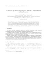
between the connected members, namely the panel zone of the column web, as shown
in Fig. 1.1. EC4 has a similar definition as depicted in Fig. 1.2.
Traditionally, a frame, either composite or bare steel is designed assuming that
its connections/joints are free to rotate or fully restrained from rotation. This
corresponds to two idealised cases, namely perfectly pinned or perfectly rigid. This
assumption disregards the inherent stiffness and moment capacity of flexible
connections and rotational flexibility of rigid connections. Perfectly pinned
connections overestimate the span moment and deflection and underestimate the
support moment. On the other hand, the assumption of perfectly rigid connection
underestimates the mid-span moment and deflection and it overestimates the support
moment. As a result, an inaccurate assessment is made towards the actual behaviour
of frames. In fact, the actual behaviour of such connections lies between these two
extreme cases and is identified as semi-rigid connections. Many practical composite
beam-to-column connections exhibit this semi-rigid characteristic and many
researchers (Benussi et al., 1989; Davison et al., 1990; Xiao et al., 1994) have carried
out experimental testing to evaluate the performance of such connections. Their
studies showed that most composite beam-to-column connections are able to generate
significant moment capacity and they should be more appropriately considered as
partial strength/semi-rigid. Modern design codes, EC3 (1992) and EC4 (1994) have
recognized these concepts.
In order to incorporate these more involved and realistic connection behaviour
into frame analysis and design, it is necessary for a designer to have knowledge of the
actual connection properties. For instance, ultimate strength design requires both
moment and rotation capacities of composite beam-to-column connections. Similarly,
a designer is required to compute the rotational stiffness of composite beam-to-
2
column connections in their serviceability checks. However, the actual behaviour of
composite connections can be rather complicated. Extensive research work has been
carried out in the past ten years. However, the process of establishing a general basis
for composite connection design has not made much progress because too many
parameters affect the behaviour of such connections. There are many aspects of the
composite connection yet to be understood. To date, the concept of semi-continuous
construction is included in modern design codes such as the BS and EC codes, but the
guidelines of the prediction of moment capacity, rotational stiffness and rotation
capacity of such connections have not been fully developed yet. More research on
composite joints is therefore needed to provide further understanding.
As a result of the intensive research worldwide into joint studies, a consistent
method to integrate the actual joint response into the frame analysis was proposed by
Huber (1999) and Jaspart (2000) recently. It is known as the Joint Representation
that includes four necessary actions, namely:
• Joint characterisation:
Evaluation through appropriate means of the stiffness, resistance and ductility
properties of the joints (either full M-φ curve or key properties).
• Joint modelling:
The way in which the joint is physically represented in view of the global
frame analysis.
• Joint Classification:
The tool providing boundary conditions for the use of conventional type of
joint modelling (e.g. rigid or pinned).
• Joint Idealisation:
3
The derivation of a simplified moment-rotation curve in order to be consistent
with specific analysis approaches (e.g. linear idealisation for an elastic
analysis).
The state of development and knowledge in these actions may be referred to
the publications by Huber (1999) and Jaspart (2000). The present study concentrates
on the Joint Characterisation.
1.2 OBJECTIVES AND SCOPE
The aim of the present investigation is to study experimentally the behaviour
of composite beam-to-column joints subjected to symmetrical and reversal of loading
conditions in order to simulate the joints in non-sway and sway composite frames.
Parameters such as reinforcement ratio, steelwork connection type, column web panel
zone stiffening method, and haunch depths are varied in the experimental program.
The effects of these parameters with respect to moment capacity, rotational stiffness
and rotation capacity are studied. Finally, design guidelines/implications for
composite flush and extended end plates and haunched joints in composite non-sway
and sway frames are proposed. The key joint properties, i.e. moment capacity, initial
stiffness and rotational capacity, especially for sway composite joints are evaluated
for global frame analysis.
Thirteen composite beam-to-column and one steel beam-to-column joints were
tested to failure in the laboratory. Six of the composite joints were tested under
symmetrical loading whereas the remainder under load reversal. Moment-rotation
relationships of the joints were studied. Analytical models to predict moment
capacities, initial stiffnesses and rotation capacities for both positive and negative
4
moment regions are proposed. Comparisons are made between experimental results
and those obtained from the analytical models for the purpose of evaluation. Simple
design procedures for the types of composite joints tested are presented.
1.3 STRUCTURE OF THE THESIS
The thesis contains six chapters, including the present one in which a general
description of the merits of composite construction and the need for further research
in composite beam-to-column joints are given and the objectives and scope of the
research highlighted in the same chapter.
Chapter 2 reviews briefly the selected literature available on composite beam-
to-column joints. Both experimental and analytical studies on composite joints for
composite braced and sway frames since the 1970s are presented. Considering the
studies carried out world wide, the impetus of the present study is illustrated.
Chapter 3 describes the experimental program for joints in non-sway (joints
tested under symmetrical loading) and sway (joints tested under reversal of loading)
composite frames. Details of the test set up and parameters varied in the investigation
are given. It also explains the loading procedure for the testing. Chapter 3 also
covers the test results obtained from the experimental program. This includes the
loading behaviour from the elastic stage to the failure stage. The actual behaviour of
composite joints tested is discussed systematically by comparing one specimen with
another, and with studies completed elsewhere. Failure modes are identified and the
effects of parameters illustrated.
Chapter 4 presents analytical models to predict the moment capacities, initial
stiffness and rotational capacities of composite joints subjected to both positive and
negative moments. The results obtained in the experimental program are compared
5
with those obtained by using the analytical models proposed, thus verifying the
models.
Chapter 5 presents the techniques to model the joint for frame global analysis
and design. The joint modelling with and without joint transformation are
demonstrated for specimens tested. The conclusions and recommendations for future
research are given in Chapter 6.
6
Fig. 1.1 Distinction between joint and connection
(Nethercot and Zandonini, 1990)
7